
 Notes on Full and Shrunken 40-Meter Quads
The limitations of shortened 40-meter Yagis has raised some interest in the possibilities of a 40-meter quad. The following notes are extrapolations from studies published in Communications Quarterly, Summer, 1997 (pp. 71- 92). The full study focused on 10 meter models and test antennas, with nearly automatic extensions of the ideas to 20 meters. However, a number of variables has required some extensive remodeling for 40-meters.
40-meters is a wide band. 300 kHz at 40 is electrically the equivalent to 600 kHz at 20 or 1.2 MHz at 10. Hence, it is inherently more difficult sustaining the performance of any type of array across the band, in addition to maintaining an inclusive operating bandwidth. Therefore, for virtually any multi-element antenna design, there will be a region of the band at which performance is peak and other parts of the band where the antenna may be operated with lesser gain and front-to-back ratio.
This restriction applies equally to quads as to Yagis, either full or half size. Moreover, reduced-size or shrunken quads will be subject to the same types of reduced bandwidth for each of the major antenna performance characteristics of greatest concern to radio amateurs: gain, front-to-back ratio, and SWR bandwidth.
Let's look at four quad possibilities: a full size model and three versions of shrunken models, and then compare their performance potentials as derived from models. All gain figures are free space gains in dBi.
In the process of comparing these antenna models, I shall by pass mechanical questions. The quad is requires a significant mechanical support structure. Companies, such as Cubex, to name just one, make support structure hardware available. Whether the resulting assembly is adequate to various climates will have to be a builder decision.
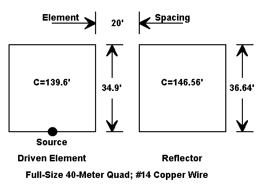
The figure shows the wire dimensions for a full size quad optimized for maximum performance at the lower end of the band. The modeled wire size for this and all models is #14 copper. If you use a fatter wire, do not expect element shortening. As Bob Haviland pointed out, as you increase the wire diameter of the quad or almost any other closed-geometry antenna, element length increases.
The 20' spacing represents a separation of about 0.14-0.15 wavelength, which is a good compromise among the major performance characteristics of the antenna. Shorter spacings are possible with a consequent narrowing of the operating bandwidth. Larger element spacing tends to increase the ungainliness of the assembly almost exponentially.
For all quad models, peak gain occurs below 7 MHz. As gain increases, the front-to-back ratio decreases. For all the models shown, a minimum band- edge front-to-back ratio of 9-10 dB was used as a design limit.
Frequency sweeps of the model show a maximum front-to-back ratio of over 29 dB at 7.1 MHz, where the gain is about 6.9 dBi. Gain is higher at lower frequencies, reaching 7.4 dBi at 7 MHz. Above the design center, both gain and front-to-back ratio show a regular decline down to 5.9 dBi and 10.2 dB at 7.3 MHz.
Since the feedpoint impedance of the antenna fluctuates around the 100-ohm mark, the antenna was designed for use with a 1/4-wavelength 75-ohm matching section. With the section in place, the antenna has a 50-ohm SWR of less than 2:1 across the band.
First, the current is still high at the corners of a full size quad. Shrinking the loop changes the polarization of the formerly corner current to vertical, where is tends to cancel with fields from the opposite side of the loop. Hence, we can expect lesser gain from every shrunken quad.
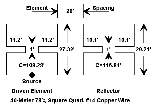
As the figure shows, we can reduce the dimensions of the quad significantly, that is, by 20 to 25%. However, in the square configuration, we are limited by the need for dimensional space for the insets. Further shrinking can be obtained by spreading the inner ends of the insets, thus decreasing their length. However, further shrinkage will be accompanied by further gain reductions.
With the dimensions shown (retaining the 20' spacing), maximum front-to- back ratio occurs between 7.05 and 7.1 MHz and peaks above 17 dB. Gain in this region is between 6 and 6.4 dBi, climbing to about 6.8 dBi at the lower band edge.
As with the full-size quad, gain and front-to-back ratio decline from 7.1 to 7.3 MHz, dropping to 4.6 dBi and 6.1 dB, respectively, at the upper band edge. Obviously, peak antenna performance appears over a narrower bandwidth with the smaller antenna.
The shrunken quad presents a feedpoint impedance apt for a 75-ohm feedline. Therefore, the antenna was designed for this feedline, with expectations of an appropriate transformation either at the antenna feedpoint or at the shack. 2:1 SWR bandwidth just about covers the entire band.
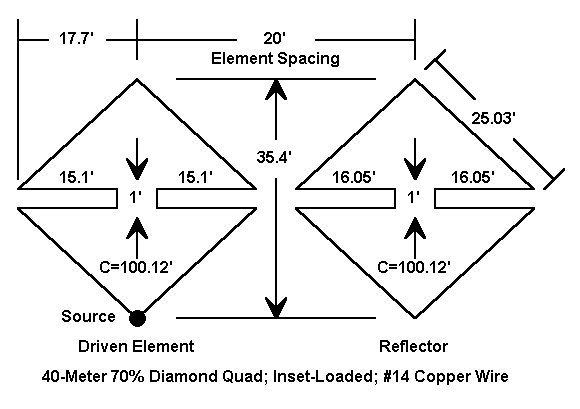
With an overall reduction of circumference to the 70% of full-size mark, the diamond configuration is at the verge of that point in antenna design where further size reductions are accompanied by much larger decreases in performance, especially with respect to gain and operating band width. Moreover, the maximum cross-arm dimensions and hence both the horizontal and vertical space required by the quad approach the horizontal and vertical dimensions of the square full-size quad. However, the diamond shrunken quad provides more space for the insets, and the configuration will be much lighter and possibly better at shedding ice and snow than wither of the square models.
The maximum front-to-back ratio of this configuration peaks just above 7.05 MHz at above 17 dB, with a gain of about 6 dBi. Lower band edge gain is close to 6.5 dBi. Gain and front-to-back ratio taper up the band to upper band-edge figures of 3.95 dBi and 4.51 dB, respectively.
Like the square inset-loaded quad, the antenna is apt for 75-ohm coax feed, and the 2:1 SWR operating band width covers just about the entire band.
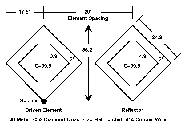
As the figure shows, the cap-hat loaded diamond is mechanically equal to the inset-loaded diamond model. The cap-hat wires perform essentially the same function as the insets: to provide the wire length necessary to reach resonance at the desired frequency without adding significantly to the radiation fields. Hence, we would expect performance figures to be equally similar.
We shall not be disappointed. Maximum front-to-back ratio once more peaks at about 18 dB at 7.05 MHz where the gain is 6.1 dBi. Gain climbs to 6.4 dBi at the band edge. Gain and front-to-back ratio decreases toward 7.3 MHz, where they are 4.1 dBi and 5.4 dB, respectively.
Insets and cap-hats present the builder with construction challenges of different but comparable sorts. The square and diamond inset models require parallel wires reaching toward (but not reaching and certainly not overlapping) the antenna boom. Lightweight spacers, perhaps 1/2" nominal CPVC, can maintain spacing while UV rated synthetic rope can serve as the insulated link to the hub support. There is no reason why the insets cannot be as much as 15 degrees off-plane without unduly affecting the front-to-side ratio of the antenna pattern. The spread cap-hat wires can be insulated and spaced from the main element wires by similar means: CPVC.
The dimensions shown are modeled dimensions and will required field alteration to account for the variables of quad construction. Unlike aluminum tubing, which is relatively rigid in length, quads are subject to changes in length depending on the tension applied by the builder during construction. The results may be changes to the insets or the cap-hat spread wires. The amount of metal, if any, in the spreaders may also require small changes in wire length. In short, wire quad dimensions are never as assured as aluminum tubing dimensions.
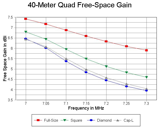
The individual models, when graphed across the band, show that gain is largely a function of percentage of full-size. The full-size quad not only has a higher forward gain than the shrunken models, but the rate of decrease is slower across the band. At the design center--about 7.05-7.1 MHz, the gain approaches that of a short boom or a wide-band 3-element Yagi and exceeds the gain of a full-size 2-element Yagi by over a half dB. (The forward gain of a full-size 2-element quad is still a dB short of the gain of a long-boom optimized 3-element Yagi.)
The 78% square inset-loaded quad shows good gain across the band relative to the smaller quads and relative to a full size 2-element Yagi. The 2 diamond 70% quads compete well with a full size 2-element Yagi and are superior to half-size Yagis. However, the shrunken quads do show a tendency to more rapidly decrease their gain across the band relative to a full size quad. However, the lowest figures remain about 2 dB better than a dipole.
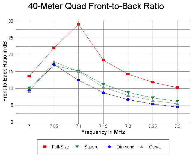
Because the full-size quad has inherently a better front-to-back ratio, it is possible to design its peak further into the 40-meter band and still have about 13 dB at the band edge. This design tactic provide better than a 10 dB front-to-back ratio at the upper end of 40 meters, despite the rapid drop in the ratio above 7.1 MHz.
All three shrunken models show front-to-back ratio curves that would be indistinguishable in practice. The square 78% model has its peak between 7.05 and 7.1 MHz, which is invisible on this sweep at 0.05 MHz intervals. However, that peak is not significantly above those of the diamonds. with a design limit that set the front-to-back ratio at 9-10 dB at the lower edge of the band, this ratio is sustained only to abut 7.15 MHz for all three models. If a builder desires to center the performance peak within the phone end of the band, he must change element dimensions. However, the antenna may become inoperative at the low end of the band if centered between 7.2 or 7.25 MHz.
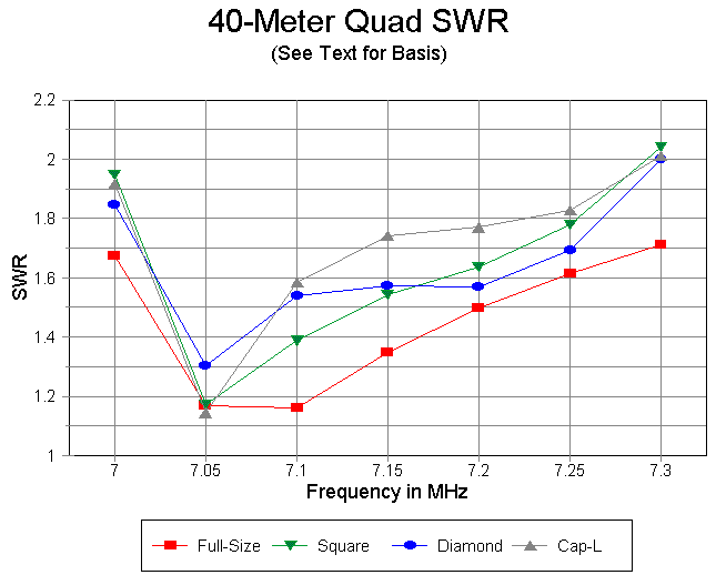
All four antenna models show a wide operating bandwidth, covering all of 40 meters. However, one should understand that the upper half of the band is achieved at significantly lower antenna performance figures.
The full-size model SWR curve is for a 50-ohm SWR basis. The model was constructed with 1/4 wavelength 75-ohm matching section cut for 7.1 MHz. The 50-ohm SWR never 1.76 across the band.
All three shrunken models are inherently 75-ohm antennas, and the SWR curves are based on 75 ohms. The use of 7.05 MHz as a design center is apparent in all of the curves.
The resonant frequency, at which the antenna shows near-zero reactance, must be set low in the band. To a degree higher than virtually any other antenna design, quads show a very rapid rise in SWR below resonance and a very slow rise in SWR above resonance. The rapid rise in SWR below design frequency is a combination of a rapid drop in the resistive component and a rapid rise in reactance. Above the resonant frequency, both the resistive and reactive components of the feedpoint impedance rise very slowly. This fact can mislead a user into believing that his antenna is performing very well, when, indeed, the low SWR is accompanied by mediocre gain and front- to-back ratio.
Consequently, it is never good practice to build a quad without making at least some measurement of the front-to-back ratio across the band in addition to impedance measurements. One can make fairly extensive changes in the driven element without affecting antenna performance. However, changes in the reflector will change the resistive and reactive components of the feedpoint impedance. Hence, for most cases, it is better to begin by establishing the reflector length with respect to front-to-back ratio pattern across the band and then adjust the driven element for the desired SWR characteristics. If the change in the driven element is quite large, it may take ne more round of reflector-then-driven-element adjustment to settle on the final dimensions.
All of the designs presented can be improved with respect to almost every characteristics. I developed them, not as the last word in 2-element 40- meter quad design, but as typical models on which to base expectations and to make design decisions for one's individual situation.
For further information on quads, see at least the following references:
William I. Orr, W6SAI, All About Cubical Quad Antennas
Bob Haviland, W4MB, The Quad Antenna
John Koszeghy, K2OB, High Performance Cubical Quad Antennas
Updated 12-30-97. © L. B. Cebik, W4RNL. Data may be used for personal purposes, but may not be reproduced for publication in print or any other medium without permission of the author.