 Modeling 6 Long-Boom Yagis
What actually emerged is a lesson in some of the difficulties in making such assessments. Some of those difficulties arise from limitations of the programs (and every version of NEC/MININEC has limitations). Others emerge from differences among models and specification sheets that cannot be resolved without additional data not at hand. Hasty modeling and simplistic conclusions can yield fog where clarity is desired.
The beams are interesting for their differing design features, not the least of which is the choice in element spacing, as shown in the figure below.
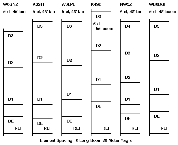
The K6STI has the lowest design feedpoint impedance, which is indicated in the reflector-driver spacing. The W6NGZ design aims for a higher feedpoint impedance and uses a correspondingly wider reflector-driver spacing. The W3LPL design has a comparable feedpoint impedance and hence a similar reflector-driver spacing to the W6NGZ design, despite the differences in boom length. These three designs are similar beyond the driver in that the directors are proportionally spaced, relative to each other. However, do not ignore the ability of D2 to affect feedpoint impedance. The WB0DGF design demonstrates how a different taper schedule may influence the required spacing for a design, since its reflector-drive spacing is greater than the K6STI antenna, but the DGF version has only a moderately higher feedpoint impedance.
The longest model (K4SB) tries for a direct 50-Ohm feed and uses the widest reflector-driver spacing. D1 is not especially different in spacing from the driver relative to the first three models. The truly different design is the NW3Z 6-element Yagi, which uses a moderately wide spacing between the reflector and driver combined with the closely spaced D1 to set the basic parameters of the antenna. However, D2 also plays a crucial role in setting the feedpoint impedance: at correct spacing, the feedpoint impedance is a good coax match; with D2 40" closer to D1, the feedpoint impedance drops to the 25-Ohm neighborhood without seriously affecting the gain and front-to-back characteristics of the antenna.
These notes are not designed to recommend one design over another, either overtly or tacitly. That would require a detailed construction analysis plus the resolution to some modeling questions which I intend to leave open.
NEC-2 without a correction factor cannot accurately model a linear element using a tapered-diameter schedule. For that reason, some implementations of NEC-2 include Leeson or similar corrections, which substitute a carefully calculated mono-tapered element for each tapered-diameter element in an array. However, it is possible to disturb the substitute element by paying too little attention to segment length equality. Especially at current nodes (the center of near-1/2 wl elements), segment length needs to be equalized along a linear element element (whether it is a single dipole or a part of a larger array). Since the Leeson corrections modify the length and diameter of a wire but not its segmentation, segment lengths should be equalized in advance. This factor plays an especially important role where the designer may place a very-large diameter short segment at the element center to simulate boom-to-element mounting plates and hardware. Often--as with the K6STI and WB0DGF models--the length of this segment sets the approximatele length of segments in the adjoining sections of the element.
Therefore, for the models at hand, segmentation was increased to yield segment lengths between 8" and 12", depending upon the model. The K6STI and WB0DGF models use the shorter lengths due to their center "lumps." (Note that the WB0DGF model omits the center "lump" on the driven element, while the K6STI model preserves it.) The W6NGZ model uses 12" segments, because they came out most even with the element sections in the design.
Other beams used 8" (W3LPL) or 10" (K4SB, NW3Z) per segment for similar reasons: the chosen segment length turned out to be the best way to achieve roughly equal length segments on the most elements. Despite best efforts, some variations inevitably result. Designers will always have, for any segment length chosen, a section that comes out to be n.5 segments long. Some will choose center sections that for any reasonable segment length seem to require an even number of segments. Adding extra segment is necessary for the driver--and hence, for the other elements in order to keep segment junctions as well aligned as possible.
NEC-4, by its initial reports, overcomes the NEC-2 weakness with tapered-diameter elements. Unfortunately, the initial reports have proven overly optimistic. Although NEC-4 is a vast improvement over uncorrected NEC-2, it falls short of the standard set by NEC-2-corrected, which also correlates with MININEC results. (MININEC does not have a tapered-diameter element problem, although it has other limitations.)
The NEC-4 limitation is somewhat minor for general purpose modeling, unless the element shows too large a diameter change between wires in the element, especially close to the current node, with the driven element the most crucial. This condition exists with the K6STI model.
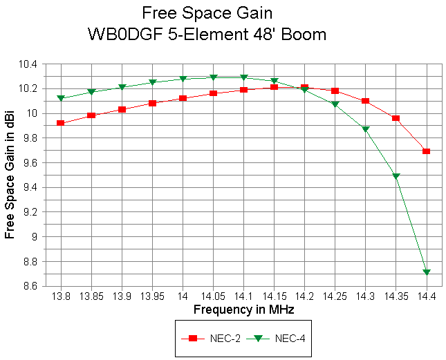
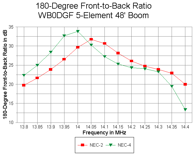
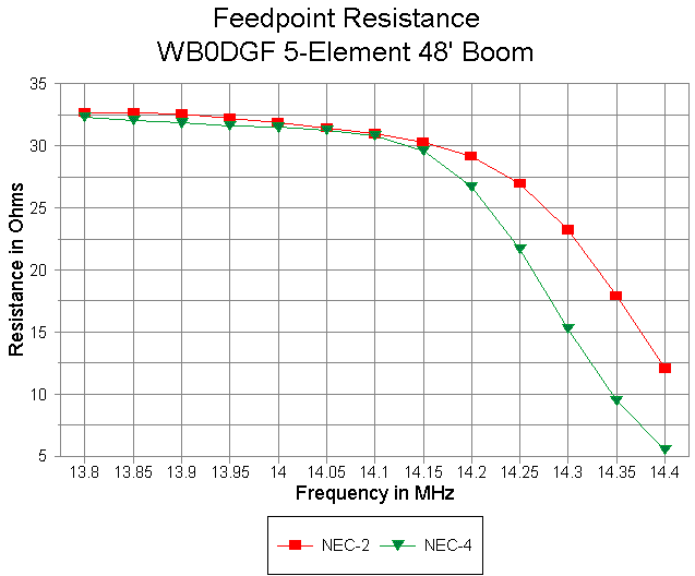
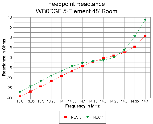
In order to show the modeling differences between NEC-2-corrected and NEC-4, I have modeled all 6 beams in both programs via EZNEC Pro. (I could have applied the Leeson equations to the NEC-4 runs, but that would have produced the same results as the NEC-2 runs.) I graphed data comparatively for NEC-2-corrected and for NEC-4, to include free space gain in dBi, 180-degree front-to-back ratio, feedpoint resistance, and feedpoint reactance. SWR data is also shown wherever the source impedance is close enough to 50-Ohms to make such data relevant. All graphs run from 13.8 to 14.4 MHz in order to show downward slides of NEC-4 curves.
Let's look at the designs individually.
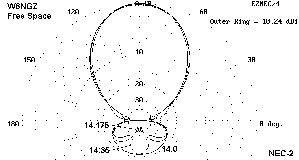
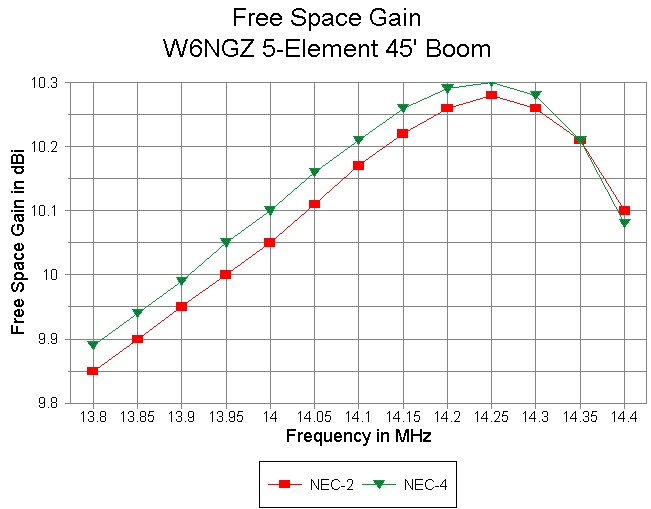
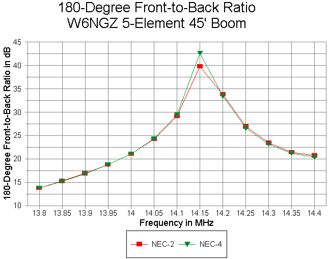
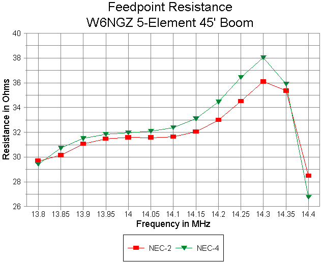
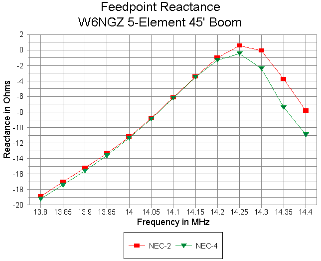
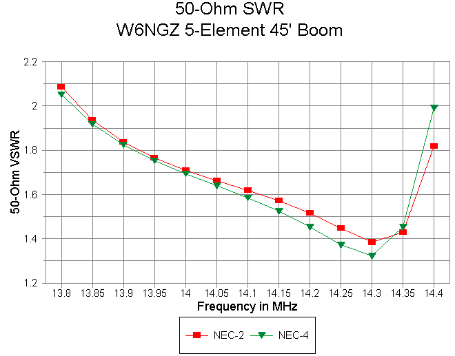
As the graphics make plain, the antenna close being a very good match for 50-ohm cable.
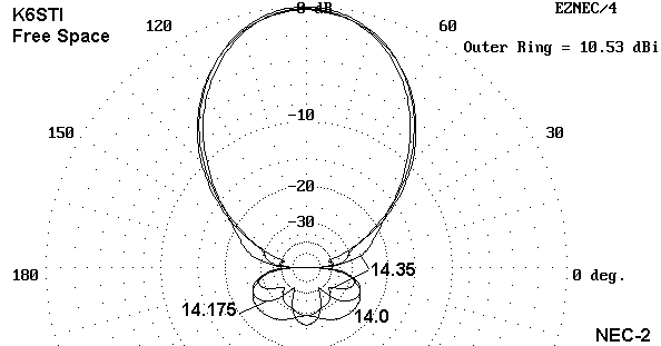
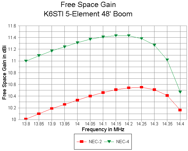
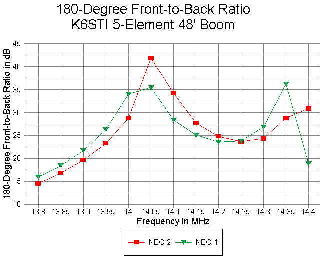
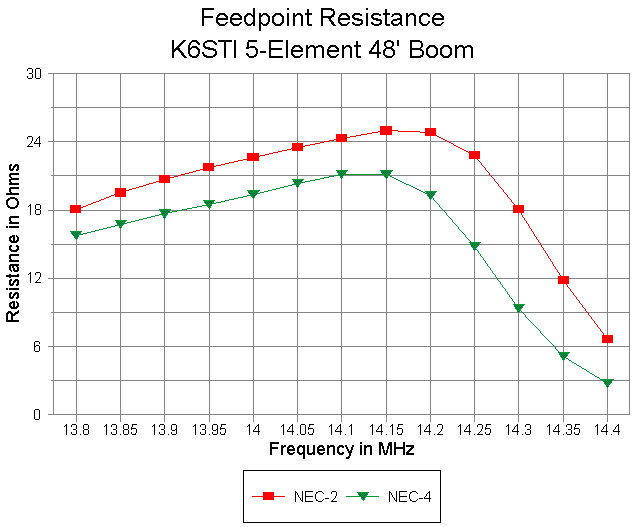
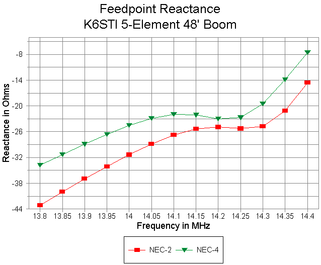
No SWR curve is shown, since the antenna is designed for a matching system such as a beta/hairpin match.
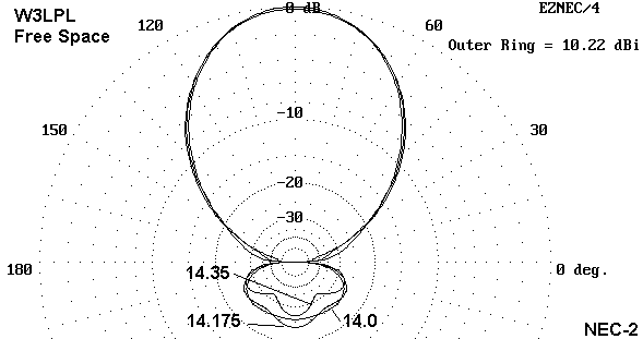
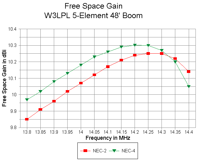
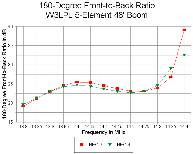
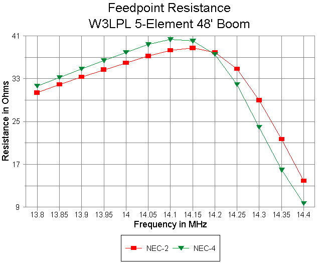
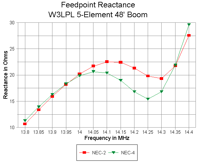
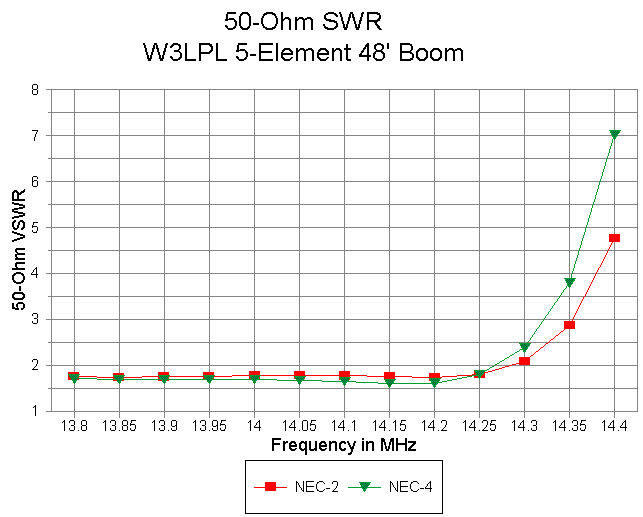
I have included the 50-Ohm SWR curve for the W3LPL antenna because it makes a good contrast with that of the W6GNZ antenna, even though the antenna designer specifically introduced the inductive reactance in the driver to set up conditions for a no-capacitor Tee match system for a 200-Ohm feed impedance. Shortening the driver to resonance in an attempt to reduce the SWR will result in a decrease in the resistive component so that no great improvement actually occurs. However, those wishing a direct 50-Ohm feed without a Tee match may wish to consider a beta match using a shunt capacitor, instead of the usual shunt inductor which is applied when the driver element is capacitively reactive. A capacitor value of about 90 Ohms reactance (about 125 pF) with sufficient voltage and current handling capabilities would come close to serving the need.
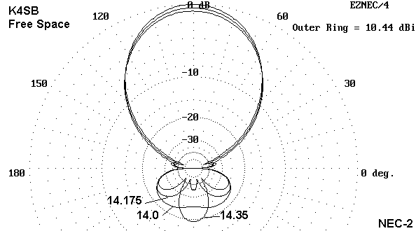
This beam is for me simply a modeling exercise and does not take into account any variations in building technique. It does not compensate for the effects of boom-to-element hardware. Considerable model tweaking would likely be required before construction.
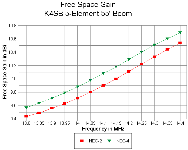
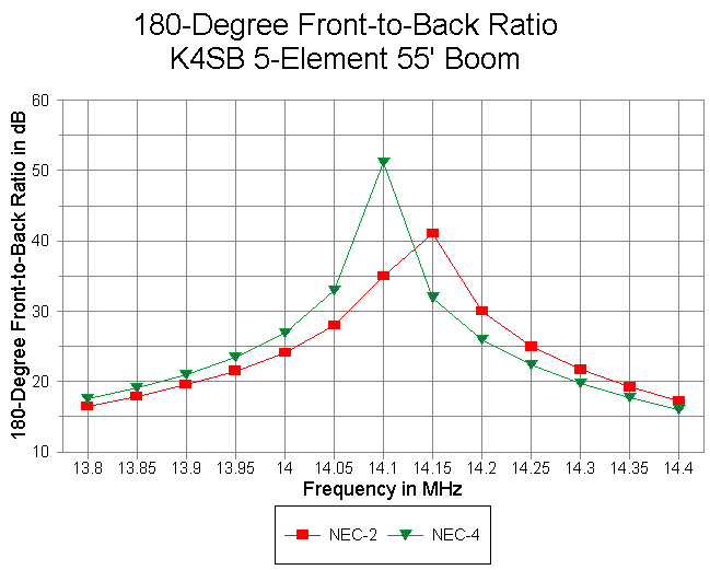
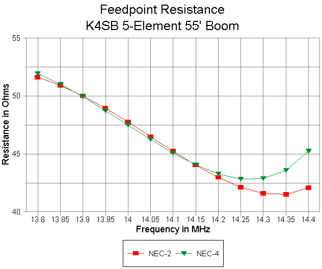
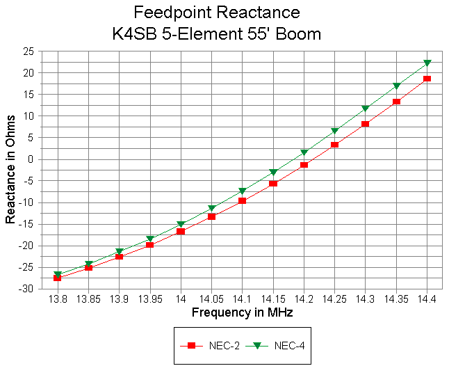
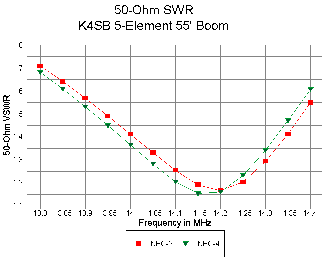
The SWR curve is quite good. There is a significant variation in reactance across the band, to go along with the variations in gain and front-to-back ratio, although the beam demonstrates close to the optimum of what may be achieved using refelctor spacing alone to determine a 50-Ohm feedpoint match.
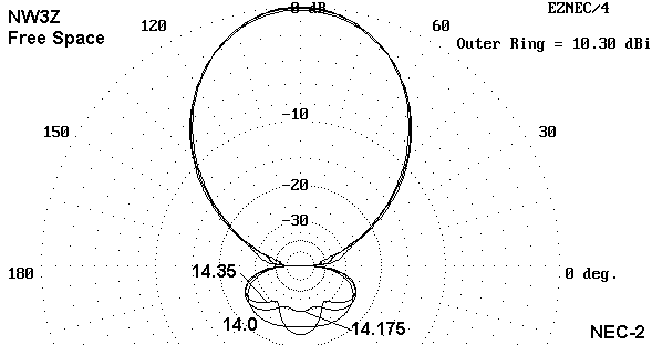
As with all other designs, NEC-4 tends to overestimate gain and move the performance characteristics lower in frequency relative to NEC-2 curves. Since this model uses a 96" constant diameter center section in each element, the effect is not too extreme, but still greater than for the W6NGZ design.
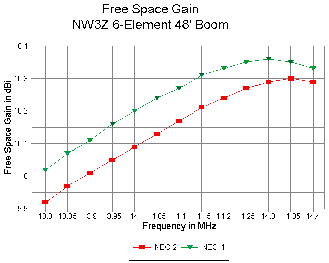
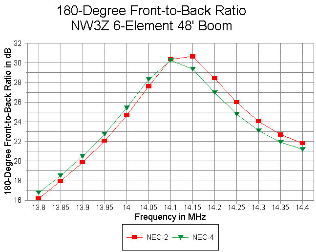
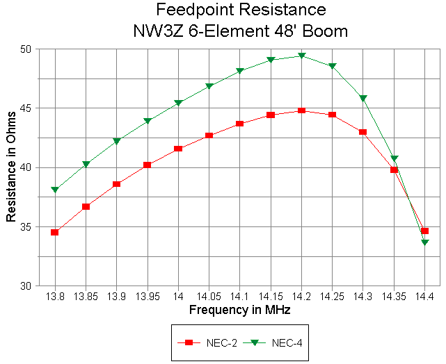
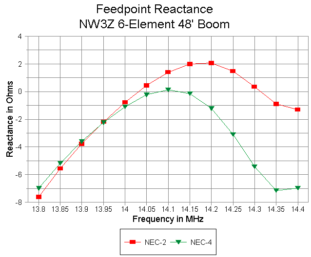
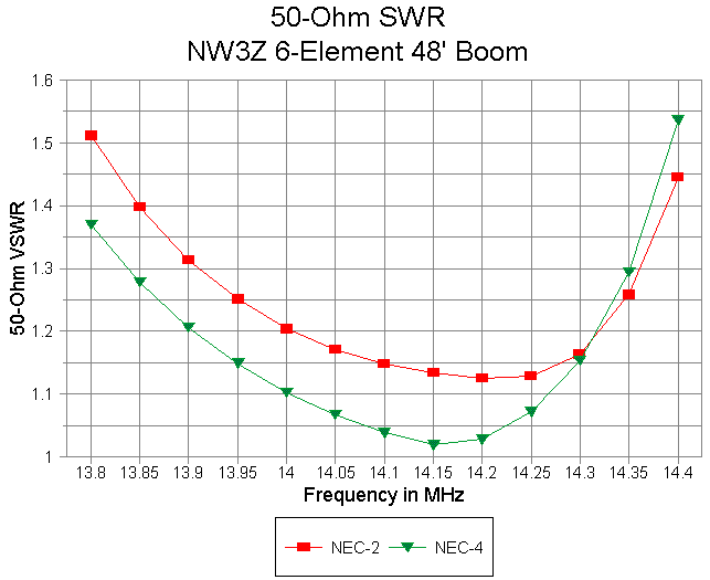
Beware of misreading the steep SWR curves: first read the axis values. Only then can you compare the numbers with those appearing in the other beam graphs.
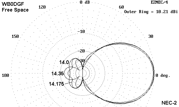
Since this antenna design was set up for potential use with a beta match system, no SWR curve is shown.
1. The beams do reveal something of the broader aspects of large Yagi behavior in the means we use to design specific feedpoint impedances while retaining the highest levels of gain and front-to-back performance. Study of the spacing sketch alone (made more precise by the EZNEC Pro file descriptions appended to this note) may give some insight into future Yagi design directions. Yagi design innovations are far from exhausted.
2. Modeling comparisons are not to be undertaken lightly or hastily. Analyzing the foundations of received models as well as those inherent in one's own creations is a necessary step if models are to be compared against some set of design or analysis goals. It would have been very easy to see two of the designs above as simply inadequate to cover the entirety of 20 meters by looking solely at NEC-4 curves, when what is more likely at work is a frequency offset. Add to this the limitations of each core used to model the structures unambiguously, and the simple conjunction of models would become a disservice to understanding the antennas involved.
Within these handicaps, the comparison of some of the best of extant long- boom 20-meter Yagi design provides an interesting and potentially productive exercise. It can assist us in understanding both antenna design and antenna modeling just a little bit better.
                      EZNEC/4  ver. 2.0

5L45' W6NGZ CQ 10-96 p 22                      07-19-1998     07:44:08


Frequency = 14.175  MHz.

Wire Loss: Aluminum -- Resistivity = 4E-08 ohm-m, Rel. Perm. = 1


              --------------- WIRES ---------------

Wire Conn. --- End 1 (x,y,z : in)  Conn. --- End 2 (x,y,z : in)   Dia(in) Segs

1          -215.60,  0.000,  0.000  W2E1 -156.00,  0.000,  0.000 6.25E-01   5
2     W1E2 -156.00,  0.000,  0.000  W3E1 -120.00,  0.000,  0.000 7.50E-01   3
3     W2E2 -120.00,  0.000,  0.000  W4E1 -72.000,  0.000,  0.000 8.75E-01   4
4     W3E2 -72.000,  0.000,  0.000  W5E1  72.000,  0.000,  0.000 1.00E+00  13
5     W4E2  72.000,  0.000,  0.000  W6E1 120.000,  0.000,  0.000 8.75E-01   4
6     W5E2 120.000,  0.000,  0.000  W7E1 156.000,  0.000,  0.000 7.50E-01   3
7     W6E2 156.000,  0.000,  0.000       215.605,  0.000,  0.000 6.25E-01   5
8          -205.95, 79.800,  0.000  W9E1 -156.00, 79.800,  0.000 6.25E-01   4
9     W8E2 -156.00, 79.800,  0.000 W10E1 -120.00, 79.800,  0.000 7.50E-01   3
10    W9E2 -120.00, 79.800,  0.000 W11E1 -72.000, 79.800,  0.000 8.75E-01   4
11   W10E2 -72.000, 79.800,  0.000 W12E1  72.000, 79.800,  0.000 1.00E+00  13
12   W11E2  72.000, 79.800,  0.000 W13E1 120.000, 79.800,  0.000 8.75E-01   4
13   W12E2 120.000, 79.800,  0.000 W14E1 156.000, 79.800,  0.000 7.50E-01   3
14   W13E2 156.000, 79.800,  0.000       205.950, 79.800,  0.000 6.25E-01   4
15         -198.21,155.160,  0.000 W16E1 -156.00,155.160,  0.000 6.25E-01   4
16   W15E2 -156.00,155.160,  0.000 W17E1 -120.00,155.160,  0.000 7.50E-01   3
17   W16E2 -120.00,155.160,  0.000 W18E1 -72.000,155.160,  0.000 8.75E-01   4
18   W17E2 -72.000,155.160,  0.000 W19E1  72.000,155.160,  0.000 1.00E+00  13
19   W18E2  72.000,155.160,  0.000 W20E1 120.000,155.160,  0.000 8.75E-01   4
20   W19E2 120.000,155.160,  0.000 W21E1 156.000,155.160,  0.000 7.50E-01   3
21   W20E2 156.000,155.160,  0.000       198.209,155.160,  0.000 6.25E-01   4
22         -196.55,337.920,  0.000 W23E1 -156.00,337.920,  0.000 6.25E-01   3
23   W22E2 -156.00,337.920,  0.000 W24E1 -120.00,337.920,  0.000 7.50E-01   3
24   W23E2 -120.00,337.920,  0.000 W25E1 -72.000,337.920,  0.000 8.75E-01   4
25   W24E2 -72.000,337.920,  0.000 W26E1  72.000,337.920,  0.000 1.00E+00  13
26   W25E2  72.000,337.920,  0.000 W27E1 120.000,337.920,  0.000 8.75E-01   4
27   W26E2 120.000,337.920,  0.000 W28E1 156.000,337.920,  0.000 7.50E-01   3
28   W27E2 156.000,337.920,  0.000       196.548,337.920,  0.000 6.25E-01   3
29         -189.90,530.400,  0.000 W30E1 -156.00,530.400,  0.000 6.25E-01   3
30   W29E2 -156.00,530.400,  0.000 W31E1 -120.00,530.400,  0.000 7.50E-01   3
31   W30E2 -120.00,530.400,  0.000 W32E1 -72.000,530.400,  0.000 8.75E-01   4
32   W31E2 -72.000,530.400,  0.000 W33E1  72.000,530.400,  0.000 1.00E+00  13
33   W32E2  72.000,530.400,  0.000 W34E1 120.000,530.400,  0.000 8.75E-01   3
34   W33E2 120.000,530.400,  0.000 W35E1 156.000,530.400,  0.000 7.50E-01   3
35   W34E2 156.000,530.400,  0.000       189.900,530.400,  0.000 6.25E-01   4

              -------------- SOURCES --------------

Source    Wire      Wire #/Pct From End 1    Ampl.(V, A)  Phase(Deg.)  Type
          Seg.     Actual      (Specified)

1           7    11 / 50.00   ( 11 / 50.00)      1.000       0.000       I

No loads specified

No transmission lines specified

Ground type is Free Space
                      EZNEC/4  ver. 2.0

5L48' K6STI YA                               07-19-1998     07:44:45


Frequency = 14.175  MHz.

Wire Loss: Aluminum -- Resistivity = 4E-08 ohm-m, Rel. Perm. = 1


              --------------- WIRES ---------------

Wire Conn. --- End 1 (x,y,z : in)  Conn. --- End 2 (x,y,z : in)   Dia(in) Segs

1          -216.50,  0.000,  0.000  W2E1 -138.00,  0.000,  0.000 5.00E-01  10
2     W1E2 -138.00,  0.000,  0.000  W3E1 -96.000,  0.000,  0.000 6.25E-01   6
3     W2E2 -96.000,  0.000,  0.000  W4E1 -48.000,  0.000,  0.000 7.50E-01   6
4     W3E2 -48.000,  0.000,  0.000  W5E1  -4.000,  0.000,  0.000 8.75E-01   5
5     W4E2  -4.000,  0.000,  0.000  W6E1   4.000,  0.000,  0.000 3.42E+00   1
6     W5E2   4.000,  0.000,  0.000  W7E1  48.000,  0.000,  0.000 8.75E-01   5
7     W6E2  48.000,  0.000,  0.000  W8E1  96.000,  0.000,  0.000 7.50E-01   6
8     W7E2  96.000,  0.000,  0.000  W9E1 138.000,  0.000,  0.000 6.25E-01   6
9     W8E2 138.000,  0.000,  0.000       216.500,  0.000,  0.000 5.00E-01  10
10         -203.50, 72.000,  0.000 W11E1 -138.00, 72.000,  0.000 5.00E-01   8
11   W10E2 -138.00, 72.000,  0.000 W12E1 -96.000, 72.000,  0.000 6.25E-01   6
12   W11E2 -96.000, 72.000,  0.000 W13E1 -48.000, 72.000,  0.000 7.50E-01   6
13   W12E2 -48.000, 72.000,  0.000 W14E1  -4.000, 72.000,  0.000 8.75E-01   5
14   W13E2  -4.000, 72.000,  0.000 W15E1   4.000, 72.000,  0.000 3.42E+00   1
15   W14E2   4.000, 72.000,  0.000 W16E1  48.000, 72.000,  0.000 8.75E-01   5
16   W15E2  48.000, 72.000,  0.000 W17E1  96.000, 72.000,  0.000 7.50E-01   6
17   W16E2  96.000, 72.000,  0.000 W18E1 138.000, 72.000,  0.000 6.25E-01   6
18   W17E2 138.000, 72.000,  0.000       203.500, 72.000,  0.000 5.00E-01   8
19         -201.75,160.000,  0.000 W20E1 -138.00,160.000,  0.000 5.00E-01   8
20   W19E2 -138.00,160.000,  0.000 W21E1 -96.000,160.000,  0.000 6.25E-01   6
21   W20E2 -96.000,160.000,  0.000 W22E1 -48.000,160.000,  0.000 7.50E-01   6
22   W21E2 -48.000,160.000,  0.000 W23E1  -4.000,160.000,  0.000 8.75E-01   5
23   W22E2  -4.000,160.000,  0.000 W24E1   4.000,160.000,  0.000 3.42E+00   1
24   W23E2   4.000,160.000,  0.000 W25E1  48.000,160.000,  0.000 8.75E-01   5
25   W24E2  48.000,160.000,  0.000 W26E1  96.000,160.000,  0.000 7.50E-01   6
26   W25E2  96.000,160.000,  0.000 W27E1 138.000,160.000,  0.000 6.25E-01   6
27   W26E2 138.000,160.000,  0.000       201.750,160.000,  0.000 5.00E-01   8
28         -198.88,359.000,  0.000 W29E1 -138.00,359.000,  0.000 5.00E-01   8
29   W28E2 -138.00,359.000,  0.000 W30E1 -96.000,359.000,  0.000 6.25E-01   5
30   W29E2 -96.000,359.000,  0.000 W31E1 -48.000,359.000,  0.000 7.50E-01   6
31   W30E2 -48.000,359.000,  0.000 W32E1  -4.000,359.000,  0.000 8.75E-01   6
32   W31E2  -4.000,359.000,  0.000 W33E1   4.000,359.000,  0.000 3.42E+00   1
33   W32E2   4.000,359.000,  0.000 W34E1  48.000,359.000,  0.000 8.75E-01   6
34   W33E2  48.000,359.000,  0.000 W35E1  96.000,359.000,  0.000 7.50E-01   6
35   W34E2  96.000,359.000,  0.000 W36E1 138.000,359.000,  0.000 6.25E-01   5
36   W35E2 138.000,359.000,  0.000       198.875,359.000,  0.000 5.00E-01   8
37         -191.62,570.000,  0.000 W38E1 -138.00,570.000,  0.000 5.00E-01   7
38   W37E2 -138.00,570.000,  0.000 W39E1 -96.000,570.000,  0.000 6.25E-01   5
39   W38E2 -96.000,570.000,  0.000 W40E1 -48.000,570.000,  0.000 7.50E-01   6
40   W39E2 -48.000,570.000,  0.000 W41E1  -4.000,570.000,  0.000 8.75E-01   6
41   W40E2  -4.000,570.000,  0.000 W42E1   4.000,570.000,  0.000 3.42E+00   1
42   W41E2   4.000,570.000,  0.000 W43E1  48.000,570.000,  0.000 8.75E-01   6
43   W42E2  48.000,570.000,  0.000 W44E1  96.000,570.000,  0.000 7.50E-01   6
44   W43E2  96.000,570.000,  0.000 W45E1 138.000,570.000,  0.000 6.25E-01   5
45   W44E2 138.000,570.000,  0.000       191.625,570.000,  0.000 5.00E-01   7

              -------------- SOURCES --------------

Source    Wire      Wire #/Pct From End 1    Ampl.(V, A)  Phase(Deg.)  Type
          Seg.     Actual      (Specified)

1           1    14 / 50.00   ( 14 / 50.00)      1.000       0.000       V

No loads specified

No transmission lines specified

Ground type is Free Space
                      EZNEC/4  ver. 2.0

5L48' W3LPL WWW                              07-19-1998     07:45:37


Frequency = 14.175  MHz.

Wire Loss: Aluminum -- Resistivity = 4E-08 ohm-m, Rel. Perm. = 1


              --------------- WIRES ---------------

Wire Conn. --- End 1 (x,y,z : in)  Conn. --- End 2 (x,y,z : in)   Dia(in) Segs

1          -217.00,  0.000,  0.000  W2E1 -150.00,  0.000,  0.000 7.50E-01   8
2     W1E2 -150.00,  0.000,  0.000  W3E1 -117.00,  0.000,  0.000 8.75E-01   4
3     W2E2 -117.00,  0.000,  0.000  W4E1 -84.000,  0.000,  0.000 1.00E+00   4
4     W3E2 -84.000,  0.000,  0.000  W5E1 -33.750,  0.000,  0.000 1.12E+00   6
5     W4E2 -33.750,  0.000,  0.000  W6E1  33.750,  0.000,  0.000 1.25E+00   9
6     W5E2  33.750,  0.000,  0.000  W7E1  84.000,  0.000,  0.000 1.12E+00   6
7     W6E2  84.000,  0.000,  0.000  W8E1 117.000,  0.000,  0.000 1.00E+00   4
8     W7E2 117.000,  0.000,  0.000  W9E1 150.000,  0.000,  0.000 8.75E-01   4
9     W8E2 150.000,  0.000,  0.000       217.000,  0.000,  0.000 7.50E-01   8
10         -212.00, 86.000,  0.000 W11E1 -150.00, 86.000,  0.000 7.50E-01   8
11   W10E2 -150.00, 86.000,  0.000 W12E1 -117.00, 86.000,  0.000 8.75E-01   4
12   W11E2 -117.00, 86.000,  0.000 W13E1 -84.000, 86.000,  0.000 1.00E+00   4
13   W12E2 -84.000, 86.000,  0.000 W14E1 -33.750, 86.000,  0.000 1.12E+00   6
14   W13E2 -33.750, 86.000,  0.000 W15E1  33.750, 86.000,  0.000 1.25E+00   9
15   W14E2  33.750, 86.000,  0.000 W16E1  84.000, 86.000,  0.000 1.12E+00   6
16   W15E2  84.000, 86.000,  0.000 W17E1 117.000, 86.000,  0.000 1.00E+00   4
17   W16E2 117.000, 86.000,  0.000 W18E1 150.000, 86.000,  0.000 8.75E-01   4
18   W17E2 150.000, 86.000,  0.000       212.000, 86.000,  0.000 7.50E-01   8
19         -199.38,171.000,  0.000 W20E1 -135.88,171.000,  0.000 7.50E-01   8
20   W19E2 -135.88,171.000,  0.000 W21E1 -102.88,171.000,  0.000 8.75E-01   4
21   W20E2 -102.88,171.000,  0.000 W22E1 -69.875,171.000,  0.000 1.00E+00   4
22   W21E2 -69.875,171.000,  0.000 W23E1 -22.000,171.000,  0.000 1.12E+00   6
23   W22E2 -22.000,171.000,  0.000 W24E1  22.000,171.000,  0.000 1.25E+00   5
24   W23E2  22.000,171.000,  0.000 W25E1  69.875,171.000,  0.000 1.12E+00   6
25   W24E2  69.875,171.000,  0.000 W26E1 102.875,171.000,  0.000 1.00E+00   4
26   W25E2 102.875,171.000,  0.000 W27E1 135.875,171.000,  0.000 8.75E-01   4
27   W26E2 135.875,171.000,  0.000       199.380,171.000,  0.000 7.50E-01   8
28         -196.25,349.000,  0.000 W29E1 -119.25,349.000,  0.000 7.50E-01  10
29   W28E2 -119.25,349.000,  0.000 W30E1 -86.250,349.000,  0.000 8.75E-01   4
30   W29E2 -86.250,349.000,  0.000 W31E1 -53.250,349.000,  0.000 1.00E+00   4
31   W30E2 -53.250,349.000,  0.000 W32E1 -22.000,349.000,  0.000 1.12E+00   4
32   W31E2 -22.000,349.000,  0.000 W33E1  22.000,349.000,  0.000 1.25E+00   5
33   W32E2  22.000,349.000,  0.000 W34E1  53.250,349.000,  0.000 1.12E+00   4
34   W33E2  53.250,349.000,  0.000 W35E1  86.250,349.000,  0.000 1.00E+00   4
35   W34E2  86.250,349.000,  0.000 W36E1 119.250,349.000,  0.000 8.75E-01   4
36   W35E2 119.250,349.000,  0.000       196.250,349.000,  0.000 7.50E-01  10
37         -183.75,570.000,  0.000 W38E1 -131.75,570.000,  0.000 7.50E-01   7
38   W37E2 -131.75,570.000,  0.000 W39E1 -98.750,570.000,  0.000 8.75E-01   4
39   W38E2 -98.750,570.000,  0.000 W40E1 -65.750,570.000,  0.000 1.00E+00   4
40   W39E2 -65.750,570.000,  0.000 W41E1 -22.000,570.000,  0.000 1.12E+00   5
41   W40E2 -22.000,570.000,  0.000 W42E1  22.000,570.000,  0.000 1.25E+00   5
42   W41E2  22.000,570.000,  0.000 W43E1  65.750,570.000,  0.000 1.12E+00   5
43   W42E2  65.750,570.000,  0.000 W44E1  98.750,570.000,  0.000 1.00E+00   4
44   W43E2  98.750,570.000,  0.000 W45E1 131.750,570.000,  0.000 8.75E-01   4
45   W44E2 131.750,570.000,  0.000       183.750,570.000,  0.000 7.50E-01   7

              -------------- SOURCES --------------

Source    Wire      Wire #/Pct From End 1    Ampl.(V, A)  Phase(Deg.)  Type
          Seg.     Actual      (Specified)

1           5    14 / 50.00   ( 14 / 50.00)      1.000       0.000       V

No loads specified

No transmission lines specified

Ground type is Free Space
                      EZNEC/4  ver. 2.0

K4SB 5-element, 55' boom                        07-19-1998     07:46:17


Frequency = 14.175  MHz.

Wire Loss: Aluminum -- Resistivity = 4E-08 ohm-m, Rel. Perm. = 1


              --------------- WIRES ---------------

Wire Conn. --- End 1 (x,y,z : in)  Conn. --- End 2 (x,y,z : in)   Dia(in) Segs

1          -217.00,  0.000,  0.000  W2E1 -152.00,  0.000,  0.000 5.00E-01   7
2     W1E2 -152.00,  0.000,  0.000  W3E1 -116.00,  0.000,  0.000 6.25E-01   4
3     W2E2 -116.00,  0.000,  0.000  W4E1 -72.000,  0.000,  0.000 7.50E-01   4
4     W3E2 -72.000,  0.000,  0.000  W5E1 -48.000,  0.000,  0.000 8.75E-01   2
5     W4E2 -48.000,  0.000,  0.000  W6E1  48.000,  0.000,  0.000 1.00E+00   9
6     W5E2  48.000,  0.000,  0.000  W7E1  72.000,  0.000,  0.000 8.75E-01   2
7     W6E2  72.000,  0.000,  0.000  W8E1 116.000,  0.000,  0.000 7.50E-01   4
8     W7E2 116.000,  0.000,  0.000  W9E1 152.000,  0.000,  0.000 6.25E-01   4
9     W8E2 152.000,  0.000,  0.000       217.000,  0.000,  0.000 5.00E-01   7
10         -207.50,182.504,  0.000 W11E1 -152.00,182.504,  0.000 5.00E-01   6
11   W10E2 -152.00,182.504,  0.000 W12E1 -116.00,182.504,  0.000 6.25E-01   4
12   W11E2 -116.00,182.504,  0.000 W13E1 -72.000,182.504,  0.000 7.50E-01   4
13   W12E2 -72.000,182.504,  0.000 W14E1 -48.000,182.504,  0.000 8.75E-01   2
14   W13E2 -48.000,182.504,  0.000 W15E1  48.000,182.504,  0.000 1.00E+00   9
15   W14E2  48.000,182.504,  0.000 W16E1  72.000,182.504,  0.000 8.75E-01   2
16   W15E2  72.000,182.504,  0.000 W17E1 116.000,182.504,  0.000 7.50E-01   4
17   W16E2 116.000,182.504,  0.000 W18E1 152.000,182.504,  0.000 6.25E-01   4
18   W17E2 152.000,182.504,  0.000       207.500,182.504,  0.000 5.00E-01   6
19         -195.53,269.544,  0.000 W20E1 -152.00,269.544,  0.000 5.00E-01   4
20   W19E2 -152.00,269.544,  0.000 W21E1 -116.00,269.544,  0.000 6.25E-01   4
21   W20E2 -116.00,269.544,  0.000 W22E1 -72.000,269.544,  0.000 7.50E-01   4
22   W21E2 -72.000,269.544,  0.000 W23E1 -48.000,269.544,  0.000 8.75E-01   2
23   W22E2 -48.000,269.544,  0.000 W24E1  48.000,269.544,  0.000 1.00E+00   9
24   W23E2  48.000,269.544,  0.000 W25E1  72.000,269.544,  0.000 8.75E-01   2
25   W24E2  72.000,269.544,  0.000 W26E1 116.000,269.544,  0.000 7.50E-01   4
26   W25E2 116.000,269.544,  0.000 W27E1 152.000,269.544,  0.000 6.25E-01   4
27   W26E2 152.000,269.544,  0.000       195.530,269.544,  0.000 5.00E-01   4
28         -192.48,448.494,  0.000 W29E1 -152.00,448.494,  0.000 5.00E-01   4
29   W28E2 -152.00,448.494,  0.000 W30E1 -116.00,448.494,  0.000 6.25E-01   4
30   W29E2 -116.00,448.494,  0.000 W31E1 -72.000,448.494,  0.000 7.50E-01   4
31   W30E2 -72.000,448.494,  0.000 W32E1 -48.000,448.494,  0.000 8.75E-01   2
32   W31E2 -48.000,448.494,  0.000 W33E1  48.000,448.494,  0.000 1.00E+00   9
33   W32E2  48.000,448.494,  0.000 W34E1  72.000,448.494,  0.000 8.75E-01   2
34   W33E2  72.000,448.494,  0.000 W35E1 116.000,448.494,  0.000 7.50E-01   4
35   W34E2 116.000,448.494,  0.000 W36E1 152.000,448.494,  0.000 6.25E-01   4
36   W35E2 152.000,448.494,  0.000       192.480,448.494,  0.000 5.00E-01   4
37         -189.42,656.474,  0.000 W38E1 -152.00,656.474,  0.000 5.00E-01   4
38   W37E2 -152.00,656.474,  0.000 W39E1 -116.00,656.474,  0.000 6.25E-01   4
39   W38E2 -116.00,656.474,  0.000 W40E1 -72.000,656.474,  0.000 7.50E-01   4
40   W39E2 -72.000,656.474,  0.000 W41E1 -48.000,656.474,  0.000 8.75E-01   2
41   W40E2 -48.000,656.474,  0.000 W42E1  48.000,656.474,  0.000 1.00E+00   9
42   W41E2  48.000,656.474,  0.000 W43E1  72.000,656.474,  0.000 8.75E-01   2
43   W42E2  72.000,656.474,  0.000 W44E1 116.000,656.474,  0.000 7.50E-01   4
44   W43E2 116.000,656.474,  0.000 W45E1 152.000,656.474,  0.000 6.25E-01   4
45   W44E2 152.000,656.474,  0.000       189.420,656.474,  0.000 5.00E-01   4

              -------------- SOURCES --------------

Source    Wire      Wire #/Pct From End 1    Ampl.(V, A)  Phase(Deg.)  Type
          Seg.     Actual      (Specified)

1           5    14 / 50.00   ( 14 / 50.00)      1.000       0.000       V

No loads specified

No transmission lines specified

Ground type is Free Space
                      EZNEC/4  ver. 2.0

NW3Z 6 el, 48' boom WWW                      07-19-1998     07:47:18


Frequency = 14.175  MHz.

Wire Loss: Aluminum -- Resistivity = 4E-08 ohm-m, Rel. Perm. = 1


              --------------- WIRES ---------------

Wire Conn. --- End 1 (x,y,z : in)  Conn. --- End 2 (x,y,z : in)   Dia(in) Segs

1          -217.73,  0.000,  0.000  W2E1 -152.00,  0.000,  0.000 5.00E-01   7
2     W1E2 -152.00,  0.000,  0.000  W3E1 -116.00,  0.000,  0.000 6.25E-01   4
3     W2E2 -116.00,  0.000,  0.000  W4E1 -72.000,  0.000,  0.000 7.50E-01   4
4     W3E2 -72.000,  0.000,  0.000  W5E1 -48.000,  0.000,  0.000 8.75E-01   2
5     W4E2 -48.000,  0.000,  0.000  W6E1  48.000,  0.000,  0.000 1.00E+00   9
6     W5E2  48.000,  0.000,  0.000  W7E1  72.000,  0.000,  0.000 8.75E-01   2
7     W6E2  72.000,  0.000,  0.000  W8E1 116.000,  0.000,  0.000 7.50E-01   4
8     W7E2 116.000,  0.000,  0.000  W9E1 152.000,  0.000,  0.000 6.25E-01   4
9     W8E2 152.000,  0.000,  0.000       217.730,  0.000,  0.000 5.00E-01   7
10         -210.70, 90.000,  0.000 W11E1 -152.00, 90.000,  0.000 5.00E-01   6
11   W10E2 -152.00, 90.000,  0.000 W12E1 -116.00, 90.000,  0.000 6.25E-01   4
12   W11E2 -116.00, 90.000,  0.000 W13E1 -72.000, 90.000,  0.000 7.50E-01   4
13   W12E2 -72.000, 90.000,  0.000 W14E1 -48.000, 90.000,  0.000 8.75E-01   2
14   W13E2 -48.000, 90.000,  0.000 W15E1  48.000, 90.000,  0.000 1.00E+00   9
15   W14E2  48.000, 90.000,  0.000 W16E1  72.000, 90.000,  0.000 8.75E-01   2
16   W15E2  72.000, 90.000,  0.000 W17E1 116.000, 90.000,  0.000 7.50E-01   4
17   W16E2 116.000, 90.000,  0.000 W18E1 152.000, 90.000,  0.000 6.25E-01   4
18   W17E2 152.000, 90.000,  0.000       210.700, 90.000,  0.000 5.00E-01   6
19         -200.80,139.520,  0.000 W20E1 -152.00,139.520,  0.000 5.00E-01   5
20   W19E2 -152.00,139.520,  0.000 W21E1 -116.00,139.520,  0.000 6.25E-01   4
21   W20E2 -116.00,139.520,  0.000 W22E1 -72.000,139.520,  0.000 7.50E-01   4
22   W21E2 -72.000,139.520,  0.000 W23E1 -48.000,139.520,  0.000 8.75E-01   2
23   W22E2 -48.000,139.520,  0.000 W24E1  48.000,139.520,  0.000 1.00E+00   9
24   W23E2  48.000,139.520,  0.000 W25E1  72.000,139.520,  0.000 8.75E-01   2
25   W24E2  72.000,139.520,  0.000 W26E1 116.000,139.520,  0.000 7.50E-01   4
26   W25E2 116.000,139.520,  0.000 W27E1 152.000,139.520,  0.000 6.25E-01   4
27   W26E2 152.000,139.520,  0.000       200.800,139.520,  0.000 5.00E-01   5
28         -194.62,266.700,  0.000 W29E1 -152.00,266.700,  0.000 5.00E-01   4
29   W28E2 -152.00,266.700,  0.000 W30E1 -116.00,266.700,  0.000 6.25E-01   4
30   W29E2 -116.00,266.700,  0.000 W31E1 -72.000,266.700,  0.000 7.50E-01   4
31   W30E2 -72.000,266.700,  0.000 W32E1 -48.000,266.700,  0.000 8.75E-01   2
32   W31E2 -48.000,266.700,  0.000 W33E1  48.000,266.700,  0.000 1.00E+00   9
33   W32E2  48.000,266.700,  0.000 W34E1  72.000,266.700,  0.000 8.75E-01   2
34   W33E2  72.000,266.700,  0.000 W35E1 116.000,266.700,  0.000 7.50E-01   4
35   W34E2 116.000,266.700,  0.000 W36E1 152.000,266.700,  0.000 6.25E-01   4
36   W35E2 152.000,266.700,  0.000       194.620,266.700,  0.000 5.00E-01   4
37         -194.63,388.440,  0.000 W38E1 -152.00,388.440,  0.000 5.00E-01   4
38   W37E2 -152.00,388.440,  0.000 W39E1 -116.00,388.440,  0.000 6.25E-01   4
39   W38E2 -116.00,388.440,  0.000 W40E1 -72.000,388.440,  0.000 7.50E-01   4
40   W39E2 -72.000,388.440,  0.000 W41E1 -48.000,388.440,  0.000 8.75E-01   2
41   W40E2 -48.000,388.440,  0.000 W42E1  48.000,388.440,  0.000 1.00E+00   9
42   W41E2  48.000,388.440,  0.000 W43E1  72.000,388.440,  0.000 8.75E-01   2
43   W42E2  72.000,388.440,  0.000 W44E1 116.000,388.440,  0.000 7.50E-01   4
44   W43E2 116.000,388.440,  0.000 W45E1 152.000,388.440,  0.000 6.25E-01   4
45   W44E2 152.000,388.440,  0.000       194.630,388.440,  0.000 5.00E-01   4
46         -187.39,570.000,  0.000 W47E1 -152.00,570.000,  0.000 5.00E-01   4
47   W46E2 -152.00,570.000,  0.000 W48E1 -116.00,570.000,  0.000 6.25E-01   4
48   W47E2 -116.00,570.000,  0.000 W49E1 -72.000,570.000,  0.000 7.50E-01   4
49   W48E2 -72.000,570.000,  0.000 W50E1 -48.000,570.000,  0.000 8.75E-01   2
50   W49E2 -48.000,570.000,  0.000 W51E1  48.000,570.000,  0.000 1.00E+00   9
51   W50E2  48.000,570.000,  0.000 W52E1  72.000,570.000,  0.000 8.75E-01   2
52   W51E2  72.000,570.000,  0.000 W53E1 116.000,570.000,  0.000 7.50E-01   4
53   W52E2 116.000,570.000,  0.000 W54E1 152.000,570.000,  0.000 6.25E-01   4
54   W53E2 152.000,570.000,  0.000       187.390,570.000,  0.000 5.00E-01   4

              -------------- SOURCES --------------

Source    Wire      Wire #/Pct From End 1    Ampl.(V, A)  Phase(Deg.)  Type
          Seg.     Actual      (Specified)

1           5    14 / 50.00   ( 14 / 50.00)      1.000       0.000       V

No loads specified

No transmission lines specified

Ground type is Free Space
                      EZNEC/4  ver. 2.0

Hy-Gain 205-XLB, 48' Boom (WB0DGF)                07-19-1998     07:55:56


Frequency = 14.175  MHz.

Wire Loss: Aluminum -- Resistivity = 4E-08 ohm-m, Rel. Perm. = 1


              --------------- WIRES ---------------

Wire Conn. --- End 1 (x,y,z : in)  Conn. --- End 2 (x,y,z : in)   Dia(in) Segs

1          -286.00,-223.75,  0.000  W2E1 -286.00,-166.00,  0.000 4.38E-01   7
2     W1E2 -286.00,-166.00,  0.000  W3E1 -286.00,-142.00,  0.000 6.25E-01   3
3     W2E2 -286.00,-142.00,  0.000  W4E1 -286.00,-91.500,  0.000 8.75E-01   6
4     W3E2 -286.00,-91.500,  0.000  W5E1 -286.00,-45.500,  0.000 1.12E+00   6
5     W4E2 -286.00,-45.500,  0.000  W6E1 -286.00, -3.625,  0.000 1.25E+00   5
6     W5E2 -286.00, -3.625,  0.000  W7E1 -286.00,  3.625,  0.000 4.00E+00   1
7     W6E2 -286.00,  3.625,  0.000  W8E1 -286.00, 45.500,  0.000 1.25E+00   5
8     W7E2 -286.00, 45.500,  0.000  W9E1 -286.00, 91.500,  0.000 1.12E+00   6
9     W8E2 -286.00, 91.500,  0.000 W10E1 -286.00,142.000,  0.000 8.75E-01   6
10    W9E2 -286.00,142.000,  0.000 W11E1 -286.00,166.000,  0.000 6.25E-01   3
11   W10E2 -286.00,166.000,  0.000       -286.00,223.750,  0.000 4.38E-01   7
12         -170.00,-209.50,  0.000 W13E1 -170.00,-156.50,  0.000 4.38E-01   7
13   W12E2 -170.00,-156.50,  0.000 W14E1 -170.00,-132.50,  0.000 6.25E-01   3
14   W13E2 -170.00,-132.50,  0.000 W15E1 -170.00,-82.000,  0.000 8.75E-01   6
15   W14E2 -170.00,-82.000,  0.000 W16E1 -170.00,-36.000,  0.000 1.12E+00   6
16   W15E2 -170.00,-36.000,  0.000 W17E1 -170.00,-10.000,  0.000 1.25E+00   3
17   W16E2 -170.00,-10.000,  0.000 W18E1 -170.00, 10.000,  0.000 1.25E+00   3
18   W17E2 -170.00, 10.000,  0.000 W19E1 -170.00, 36.000,  0.000 1.25E+00   3
19   W18E2 -170.00, 36.000,  0.000 W20E1 -170.00, 82.000,  0.000 1.12E+00   6
20   W19E2 -170.00, 82.000,  0.000 W21E1 -170.00,132.500,  0.000 8.75E-01   6
21   W20E2 -170.00,132.500,  0.000 W22E1 -170.00,156.500,  0.000 6.25E-01   3
22   W21E2 -170.00,156.500,  0.000       -170.00,209.500,  0.000 4.38E-01   7
23         -80.000,-206.25,  0.000 W24E1 -80.000,-156.50,  0.000 4.38E-01   6
24   W23E2 -80.000,-156.50,  0.000 W25E1 -80.000,-132.50,  0.000 6.25E-01   3
25   W24E2 -80.000,-132.50,  0.000 W26E1 -80.000,-82.000,  0.000 8.75E-01   6
26   W25E2 -80.000,-82.000,  0.000 W27E1 -80.000,-36.000,  0.000 1.12E+00   6
27   W26E2 -80.000,-36.000,  0.000 W28E1 -80.000, -3.625,  0.000 1.25E+00   4
28   W27E2 -80.000, -3.625,  0.000 W29E1 -80.000,  3.625,  0.000 4.00E+00   1
29   W28E2 -80.000,  3.625,  0.000 W30E1 -80.000, 36.000,  0.000 1.25E+00   4
30   W29E2 -80.000, 36.000,  0.000 W31E1 -80.000, 82.000,  0.000 1.12E+00   6
31   W30E2 -80.000, 82.000,  0.000 W32E1 -80.000,132.500,  0.000 8.75E-01   6
32   W31E2 -80.000,132.500,  0.000 W33E1 -80.000,156.500,  0.000 6.25E-01   3
33   W32E2 -80.000,156.500,  0.000       -80.000,206.250,  0.000 4.38E-01   6
34          86.000,-203.25,  0.000 W35E1  86.000,-156.50,  0.000 4.38E-01   6
35   W34E2  86.000,-156.50,  0.000 W36E1  86.000,-132.50,  0.000 6.25E-01   3
36   W35E2  86.000,-132.50,  0.000 W37E1  86.000,-82.000,  0.000 8.75E-01   6
37   W36E2  86.000,-82.000,  0.000 W38E1  86.000,-36.000,  0.000 1.12E+00   6
38   W37E2  86.000,-36.000,  0.000 W39E1  86.000, -3.625,  0.000 1.25E+00   4
39   W38E2  86.000, -3.625,  0.000 W40E1  86.000,  3.625,  0.000 4.00E+00   1
40   W39E2  86.000,  3.625,  0.000 W41E1  86.000, 36.000,  0.000 1.25E+00   4
41   W40E2  86.000, 36.000,  0.000 W42E1  86.000, 82.000,  0.000 1.12E+00   6
42   W41E2  86.000, 82.000,  0.000 W43E1  86.000,132.500,  0.000 8.75E-01   6
43   W42E2  86.000,132.500,  0.000 W44E1  86.000,156.500,  0.000 6.25E-01   3
44   W43E2  86.000,156.500,  0.000        86.000,203.250,  0.000 4.38E-01   6
45         286.000,-193.12,  0.000 W46E1 286.000,-138.25,  0.000 4.38E-01   7
46   W45E2 286.000,-138.25,  0.000 W47E1 286.000,-114.25,  0.000 6.25E-01   3
47   W46E2 286.000,-114.25,  0.000 W48E1 286.000,-63.750,  0.000 8.75E-01   6
48   W47E2 286.000,-63.750,  0.000 W49E1 286.000,-17.750,  0.000 1.12E+00   6
49   W48E2 286.000,-17.750,  0.000 W50E1 286.000, -3.625,  0.000 1.25E+00   2
50   W49E2 286.000, -3.625,  0.000 W51E1 286.000,  3.625,  0.000 4.00E+00   1
51   W50E2 286.000,  3.625,  0.000 W52E1 286.000, 17.750,  0.000 1.25E+00   2
52   W51E2 286.000, 17.750,  0.000 W53E1 286.000, 63.750,  0.000 1.12E+00   6
53   W52E2 286.000, 63.750,  0.000 W54E1 286.000,114.250,  0.000 8.75E-01   6
54   W53E2 286.000,114.250,  0.000 W55E1 286.000,138.250,  0.000 6.25E-01   3
55   W54E2 286.000,138.250,  0.000       286.000,193.125,  0.000 4.38E-01   7

              -------------- SOURCES --------------

Source    Wire      Wire #/Pct From End 1    Ampl.(V, A)  Phase(Deg.)  Type
          Seg.     Actual      (Specified)

1           2    17 / 50.00   ( 17 / 50.00)      0.707       0.000       V

No loads specified

No transmission lines specified

Ground type is Free Space
Any transcription errors in the above models are strictly my own fault, and I shall gladly correct any found.
Updated 7-20-98. © L. B. Cebik, W4RNL. Data may be used for
personal purposes, but may not be reproduced for publication in print or
any other medium without permission of the author.