 The "Ideal" Back-Up Antenna for 80-20 Meters
Everyone needs a back-up antenna in case one or more of the main arrays at the antenna farm becomes inoperative. The requirements for the back-up antenna are very straightforward:
For this exercise, I shall confine myself to horizontal antennas, with the proviso that they be as high as possible. 70' is not very high on 80 meters for a horizontal antenna, and I shall use that as my minimum height. However, if the back-up is to replace wounded high-altitude horizontal beams, 100' is not unrealistic. If you live in the right kind of forest, these heights can be attained using trees instead of towers as the end support points.
These notes do not imply that a vertical does not make a good back-up for the main antenna systems. In fact, I use a multi-band vertical myself for just such purposes. However, it is too difficult to cover both vertical and horizontal possibilities in one small article, so I shall confine the discussion to horizontal antennas.
If we begin with a single horizontal wire, placed as high as we can achieve, only one question remains: how long? Figure 1 suggests the answer I would give.
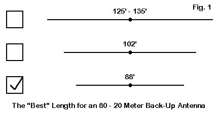
Notice that I have by-passed the standard multi-band doublet lengths of 135' and 102' (or thereabouts). The reason is simple. As we increase frequency, the azimuth patterns for these antennas break into many lobes, with much reduced radiation broadside to the wire. I shall take the following condition to be desirable for a back-up antenna: We know where the main lobes of the pattern go. The best way to guarantee consistency for all the bands we wish to cover with the back-up antenna is to ensure that the lobes on every band are broadside to the wire.
88'--plus or minus a non-critical bit--is the longest wire we can use to ensure broadside lobes on 20 meters. The antenna length is about 1.25 wavelengths on 20, which makes it an extended double Zepp. At the same time, the chosen length is between one- third and three-eighths wavelength on the low end of 80 meters. As we shall see, we lose very little performance relative to a half-wavelength dipole, but maintain a source impedance that we have a chance of matching with most common antenna tuners.
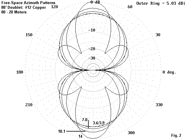
Figure 2 shows the free-space azimuth patterns for the back-up antenna for 80 through 20 meters. You may correlate the patterns with the data in Table 1.
            Table 1.  Free-Space Performance of an 88' #12 Copper Wire Doublet
            Freq.       F-S Gain    Horizontal        Feedpoint Z
            MHz           dBi       B/W (deg.)        R +/- jX Ohms
             3.6        1.77        85                  25 - j 615
             3.9        1.82        84                  30 - j 500
             7.0        2.38        71                 185 + j 510
            10.1        3.36        53                3360 + j2245
            14.0        5.03        32                 155 - j 805
Of course, these NEC-4 modeling numbers are more precise than would be operationally significant. However, they do clearly show the trends in performance. An often overlooked figure of merit is the beamwidth, which gives us a measure of relative coverage for an antenna.
No one has ever decreed that we cannot make an 88' doublet out of aluminum tubing. Before we dream of rotating such an antenna, let's examine the free-space performance figures for a version with an average effective diameter of 1". Table 2 tells the story.
           Table 2.  Free-Space Performance of an 88' 1" Aluminum Tubing Doublet
            Freq.       F-S Gain    Horizontal        Feedpoint Z
            MHz           dBi       B/W (deg.)        R +/- jX Ohms
             3.6        1.90        85                  24 - j 425
             3.9        1.93        84                  29 - j 340
             7.0        2.44        71                 197 + j 385
            10.1        3.43        53                2560 + j 220
            14.0        5.02        31                 125 - j 495
There are some interesting differences between the numbers in the two tables. First, the trend with the fatter element is higher (but not significantly higher) gain--except for 20 meters. Here, the gain actually decreases (although insignificantly), because the fatter wire more closely approaches an electrical length where the EDZ ears come to dominate the azimuth pattern. At an electrical length of 1.5 wavelengths, the antenna would show 6 nearly equal lobes.
Second, the fatter wire tends to reduce the feedpoint impedance, especially the reactive components. This effect can be very useful in easing the burden on the ATU. One of the limiting factors for every ATU is the range of reactance it is able to compensate for at any given frequency. Of course, if we choose the "wrong" line length, we may encounter such cases due to the impedance transformation properties of every transmission line. One easy solution is to change the line length until we reach the best compromise setting.
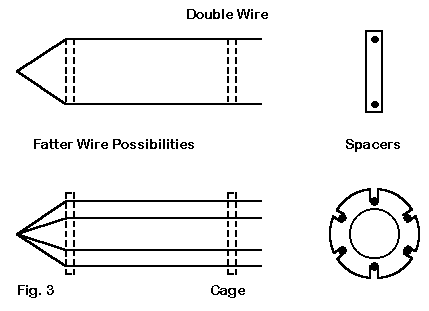
For those who would like the benefits of tubing but the low cost and lighter weight of wire, Figure 3 offers a couple of the many alternatives. We can simulate the diameter of any size tubing with a pair of wires spaced by a certain distance. The spacing would have the value that allows the antenna to be naturally resonant on the same frequency at which the tubular antenna is resonant. This is an easy modeling task that takes the work out of field adjustment.
An alternative to the paired wire arrangement (shorted at both the outer end and at the feedpoint) is the old-fashioned cage. Since everything old becomes new again, cage antennas for low-band dipole use have gained a certain popularity, especially as the newer polycarbonate plastics have become generally available. As these figures suggest, the cage may also have some utility for multi-band doublets.
Even more significant are the figures for the doublet's performance over ground. Table 3 and Table 4 list the figures for heights of 70' and 100'. Added to the table is the TO angle (the take-off angle or elevation angle of maximum radiation) and the vertical beamwidth. Together, these figures gives us a view of the range of incoming and outgoing skip angles over which we may effect communications. Like the horizontal beamwidth, the vertical beamwidth is a much overlooked valuable piece of data.
                Table 3.  70' Performance of an 88' #12 Copper Wire Doublet
Freq.       F-S Gain    TO Angle    Vertical    Horizontal  Feedpoint Z
MHz           dBi       (deg.)      B/W (deg.)  B/W (deg.)  R +/- jX Ohms
 3.6         5.90       59          130         180           30 - j 610
 3.9         5.86       53          134         180           35 - j 495
 7.0         7.84       28           33          79          165 + j 485
10.1         8.66       19           21          55         3810 + j2160
14.0        10.81       14           15          33          155 - j 820

               Table 4.  100' Performance of an 88' #12 Copper Wire Doublet
Freq.       F-S Gain    TO Angle    Vertical    Horizontal  Feedpoint Z
MHz           dBi       (deg.)      B/W (deg.)  B/W (deg.)  R +/- jX Ohms
 3.6         6.12       38           57         107           30 - j 620
 3.9         6.40       36           47         102           35 - j 505
 7.0         7.83       20           21          74          185 + j 530
10.1         9.16       14           14          54         3115 + j2450
14.0        10.50       10           10          32          165 - j 810
The feedpoint impedances at the two levels fall well within the margins of rough equality. The most important differences show up in the gain and TO angle columns. Although usable, the 70' model shows very high TO angles and lower gain on 80 meters. The 180-degree beamwidths on 80 meters indicate nearly circular patterns. In contrast, the TO angles and vertical beamwidths for 80 meters in the 100' model promise significantly better DX performance, with much more oval patterns. On 40 through 20 meters, the gain differentials disappear, but the higher model shows the expected lower TO angles.
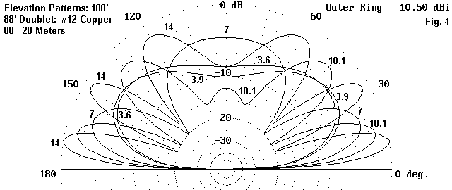
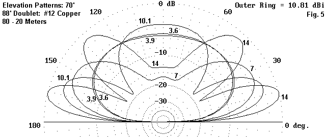
In order to get a better perspective on the significance of these figures, examine Figure 4 and Figure 5. They show the elevation patterns of the antenna at the two heights: 100' and 70', respectively. Besides illustrating the notes just given, they also reveal the growth of secondary lobes at the upper frequencies as we raise the antenna by 30' or so. 20 meters has grown a third elevation lobe. The high dome pattern gravitates from 10.1 MHz down to 7 MHz in the move from 70' to 100'. The shape difference at the two heights in the 80/75 meter patterns is self-evident.
I have not added the azimuth patterns, since they resemble too closely the patterns in Figure 2. The key difference is that as we reduce the frequency of use, the side rejection decreases. The decrease is more radical at the lower height, where it disappears almost completely at 80 meters.
Although it is not likely to be true, let me assume that I have convinced you that an 88' doublet is the best single-wire back-up antenna for 80 through 20 meters. Once we have gone this far for the sake of the argument, we can pose the question of how to derive the best world-wide coverage with such a wire antenna. The answer is as simple as the triangle.
Actually, I want to explore two versions of the triangle: a Y-array and a true triangle. For no particular reason, I shall begin with the Y-array, shown in Figure 6.
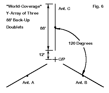
As the figure shows, the ends of the wires are set 12' from a center-point for the array. The array would require a rectangle about 100' by 175' for implementation. A 4- post construction method seems most obvious (1 at the center and three on the perimeter). However, those with special skills in high-strength wire trussing might manage with only the perimeter posts. A slight dip in antenna height toward the center point would create no significant performance problems
There is no special magic to my choice of element separation from the center point. The goal was to minimize interaction between the active element and the inactive ones. 18' between adjacent ends is sufficient to achieve this goal, as evidenced by the modeled data in Table 5. The data are for a 100' array height.
          Table 5.  100' Performance of a Y-Array of 88' #12 Copper Wire Doublets
Freq.       F-S Gain    TO Angle    Vertical    Horizontal  Feedpoint Z
MHz           dBi       (deg.)      B/W (deg.)  B/W (deg.)  R +/- jX Ohms
 3.6         6.11       38           58         108           31 - j 620
 3.9         6.38       36           47         104           35 - j 505
 7.0         7.87       19           21          73          185 + j 535
10.1         9.14       13           14          55         3110 + j2470
14.0        10.39       10           10          33          165 - j 810
The data are insignificantly different from those of Table 4, which gives modeled values for an independent 88' doublet.
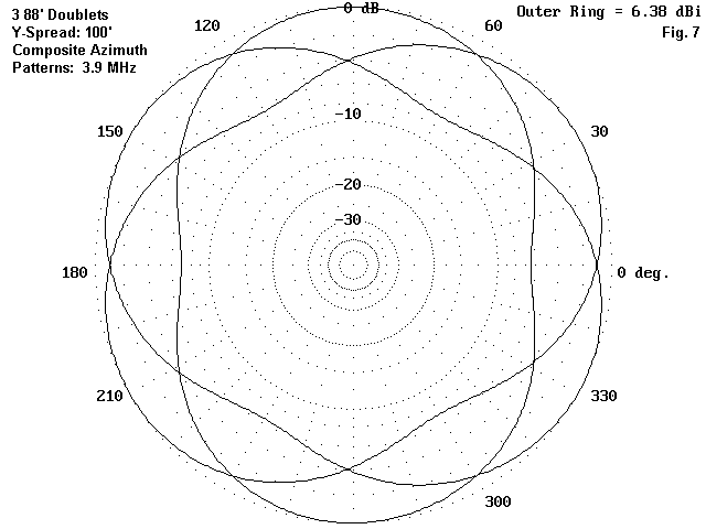
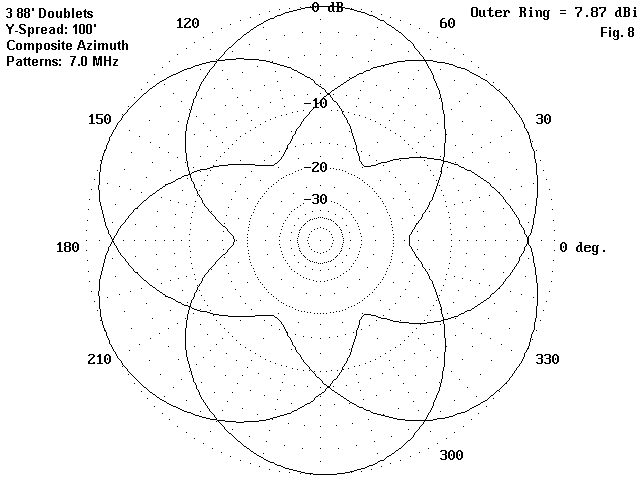
To effect world wide-communications, we should understand how the patterns for the triangle overlap. As well we should examine the nulls in the pattern. As Figure 7 attests, on 80 meters, there is no significant null (<1 dB). On 40 meters (Figure 8), the nulls are only about 2 dB, which is likely small enough not to occasion any repositioning of wires.
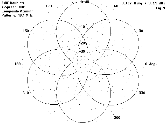
The first band on which we discover nulls deep enough to cause concern is 30 meters (Figure 9). The nulls become very much deeper on 20 meters (Figure 10), where the EDZ narrow beamwidth becomes quite significant in antenna planning.
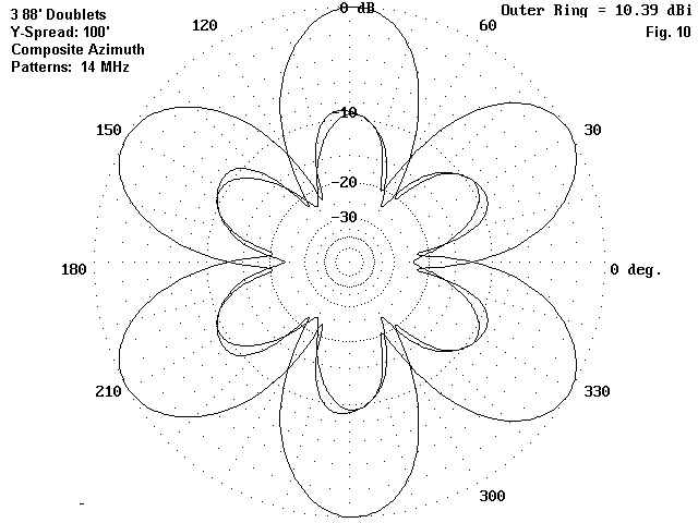
In modeling exercises, no negative effects resulted from warping the Y array from its perfect 120-degree separation. Changes up to 20 degrees appear not to create any noticeable consequences for the radiation patterns from the individual antenna wires. Consequently, the array designer can position the three wires in an approximate Y, with each wire broadside to the most favored contact directions, whether those are domestic or DX.
It would be incorrect to say that the wires do not interact at all. Figure 10 shows the very slight interaction by the manner in which the secondary lobes of the three patterns overlap in slightly irregular ways. In fact, the main lobes depart from the true broadside by about 1 degree in the direction of the other wires. These facts, however, do no more than complete the record. Their operational significance is negligible, and the three wires may be considered as aiming in a true broadside direction for all practical purposes.
The Y-array presumes that all of the parallel feedlines will be brought to a central switching point, from which a single parallel feedline will proceed to the shack. Switching would be by a remote system (unless the shack is located approximately under the center-point of the array. Figure 11 provides the basic elements of such a remote switching system.
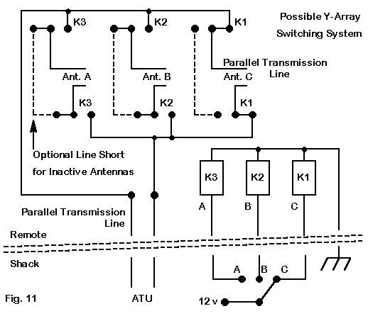
The system shown can be considered a "bare-bones" version that can be embellished in innumerable ways. Since the array shows no significant differences between open and closed centers for the inactive antennas, shorting the transmission lines of the unused antennas can serve useful functions. For example, you might want to add RF chokes to the shorted contacts with a subsequent lead to ground. The result will be to bleed off any static charges on these wires.
In fact, you may wish to add a fourth "Off" position to the switching system, for use when the array is wholly inactive. This option would simply remove all power from the relays and bleed all three wires of static charges that may build up from winds and other weather forces. (I shall assume that there will be provisions nearer to the shack for a total disconnect and grounding of both the relay power lines and the parallel transmission line coming from the switching unit. Add other safety features as the spirit moves you.)
In addition to safety features, it also pays to decouple the relay power lines from RF right at the switching unit. You may add rf chokes and by-pass capacitors to each power lines inside the weatherproof relay box. Alternatively, you can place ferrite cores over each power lines. Be sure to include the common in this treatment. Although shown with a ground connection at the shack, this line at the remote switching unit is ripe for RF pick-up and distribution. Additional decoupling at the shack end of the line is also a wise precaution.
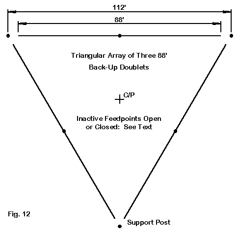
The same switching unit can be used with the second configuration of the array: the true triangle shown in Figure 12. This arrangement requires only 3 posts, about 112' apart. The outer dimensions allows for a 12' spacing of the wire from the post, which results in 12' of separation between adjacent wire ends. The true triangle requires less space than the Y-array. A rectangle about 112' by 97' will contain all of the wires. Like the Y- array, I shall assume that the feedlines are brought to a central point for switching among the antennas.
The true triangular array in theory shows more tendency toward interaction between the active antenna and the inactive wires. Hence, there is likely to be a more significant difference in performance based on whether the center points of the inactive wires are open or shorted.
The interaction does not greatly affect the overall performance of the antenna, as shown in Table 6 and Table 7. With the unused centers closed or shorted, there is a very slight front-to-back ratio. It is never greater than 0.3 dB and the "stronger" lobe is in the direction of the unused wires. With the unused wire centers open, the front-to-back effect drops to less than 0.1 dB on all but 30 meters.
      Table 6.  100' Performance of a Triangle-Array of 88' #12 Copper Wire Doublets
                                  (Unused Centers Closed)
Freq.       F-S Gain    TO Angle    Vertical    Horizontal  Feedpoint Z
MHz           dBi       (deg.)      B/W (deg.)  B/W (deg.)  R +/- jX Ohms
 3.6         6.25       38           55         109           28 - j 615
 3.9         6.57       35           46         103           32 - j 500
 7.0         7.61       20           21          71          185 + j 525
10.1         9.31       13           14          56         3320 + j2655
14.0        10.22       10           10          32          165 - j 820

      Table 7.  100' Performance of a Triangle-Array of 88' #12 Copper Wire Doublets
                                   (Unused Centers Open)
Freq.       F-S Gain    TO Angle    Vertical    Horizontal  Feedpoint Z
MHz           dBi       (deg.)      B/W (deg.)  B/W (deg.)  R +/- jX Ohms
 3.6         6.14       38           57         108           29 - j 620
 3.9         6.42       35           47         101           34 - j 505
 7.0         7.88       19           21          76          185 + j 535
10.1         9.38       13           14          62         3050 + j2490
14.0        10.16       10           10          32          170 - j 820
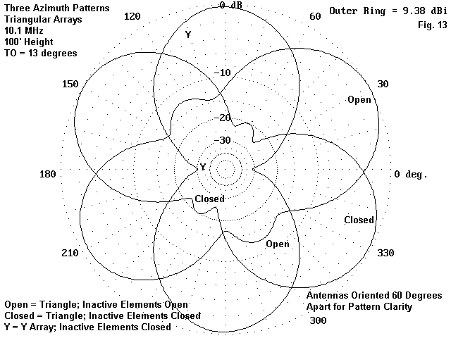
In reality, a noticeable difference in pattern shape occurs only on 30 meters. Figure 13 compares the 30-meter patterns for a. the Y-array (which is virtually identical to the pattern of the independent doublet), b. the triangle with the unused centers closed, and c. the triangle with the unused centers open. I chose a different orientation for each antenna, since the key pattern alteration occurs near pattern center. The side "bulges" in the 30-meter patterns for the true triangle do not materially affect the gain of the main lobes. However, the open condition does yield a front-to-back ratio of 0.6 dB, which can be noticed on patterns, but not in operation.
In the end, then, you may take your choice of open or closed unused elements. Since the choice is so close in performance, my own preference would be to opt for the safest choice: lines closed at the remote switching center. Whether that choice results in electrically closed or open feedpoints for the unused elements depends on the exact length of the line used between the elements and the switching box. Quarter-wavelength lines will result in open centers, while half-wavelength lines will yield shorted centers. Shorted lines that are longer than 1/4 wavelength will add capacitive reactance to the wires and possible increase the directive effect in the direction of the unused wires. Shorted lines shorter than 1/4 wavelength or longer than 1/2 wavelength will likely add inductive reactance to the unused wires, converting them into reflectors of sorts. The effect, of course, will vary from band-to-band, since the line length to the switching box will change its electrical length with changes of frequency.
For many applications, minor directive and reflective effects may be no hindrance, and the smaller footprint of the true triangle will be the overriding consideration. For some applications, maximum isolation of each antenna will be the dominant concern: in such cases, the Y-array should be the configuration of choice. Before making this decision, it would likely be wise to model the system--with the proposed feedline as part of the model--to gain a better view of actual effects.
Before leaving the field of back-up wire antennas that are about 88' long and that cover 80 through 20 meters, we should take note of the expanded lazy-H, which likely first appeared in print in CQ in an article by W2EEY. Figure 14 shows the essential elements of the array: wires vertically spaced 44' apart. Although there are monoband schemes for bottom feeding the array, multi-band use tends to require balanced in phase feeding of the system, as shown in the sketch.
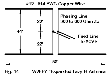
As we did with the independent doublet and the triangular arrays, let's place this antenna at a top height of 100', with the lower wires at 56'. For the data in Table 8, I used a 450-Ohm phasing line and took that feedpoint impedance readings from the junction of the two 22' lines.
     Table 8.  100' Performance of an Expanded Lazy-H of 88' #12 Copper Wire Doublets
Freq.       F-S Gain    TO Angle    Vertical    Horizontal  Feedpoint Z
MHz           dBi       (deg.)      B/W (deg.)  B/W (deg.)  R +/- jX Ohms
 3.6         5.95       46          138         131           10 - j  95
 3.9         6.05       43          141         118           15 - j  60
 7.0         9.02       23           27          76          455 - j 445
10.1        11.69       16           18          56           20 - j  45
14.0        14.87       11           12          32           50 + j 385
We should divide our discussion of the performance between the lower bands and the upper bands for this antenna. The lower bands show lesser gain and higher TO angles than the independent doublet. This phenomenon results from the fact that the elevation angle at any frequency is a composite angle of the upper and lower wires. The lower wire at 56' significantly increases the 80/75-meter TO angle. The vertical beamwidth is very wide, which may compensate to a degree by offering low angle performance not far down from maximum. However, on the lowest band, the high angle reception is likely to increase the overall noise in relationship to signal strength. Hence, for 80 and 75 meters, finding a way to disable the lower wire and using only the upper wire would make good operating sense. On 40 meters, the added gain compared to a single doublet may more fully compensate for the slightly higher TO angle.
Upper band performance of the Lazy-H is marked by very significant increases in gain over a single doublet without decreases in the horizontal beamwidth. Where the gain comes from appears in Figure 15, an elevation plot for 30 meters.
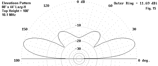
Compare this plot to the 30-meter trace in Figure 4. That plot shows a very strong second elevation lobe at about a 45-degree elevation angle, along with the "dome" that indicates the development of third lobes. The expanded Lazy-H (which is a little under 1 wavelength long on 30 meters) shows strong first elevation lobes with second lobes about 10 dB lower in strength. The 20-meter elevation pattern would show a similar plot, with more ripples but no added strength above the first lobe. The added gain in the lewest lobes comes from the reduction in high angle gain--a very nice trade indeed.
I have not modeled a Y-array of three expanded lazy-Hs, but I would suspect that the end-to-end isolation of the antennas would be similar to that of the doublets. If we have three (or 4) tall poles, towers, or trees for the support of a doublet array, we might wish to think about the expanded lazy-H as an alternative--at least for all of the bands except 80/75 meters.
The horizontal wire back-up antennas and arrays I have described depend on height for good performance on all bands. If you have the structures in place--or if you are thinking about how to place towers for a major antenna farm for the lower bands, you might seriously consider setting them up so as to support one or more of the suggested antennas as the system back-up. They offer to take up the slack in operations when the main systems are down.
However, if you only have the trees or poles with no present antennas, you may wish to give one of these arrays another kind of serious consideration. Although I have called the 88' doublet a good back-up antenna relative to larger systems, there is no reason that it cannot form the basis of a very good main system on its own. It is at least worthy of thoughtful investigation during the planning stages of a low-band antenna farm.
The key to the system is the property of the 88' doublet to have true bi-directional patterns on all of the bands from 80 through 20 meters. (We can do--and I have elsewhere done--a similar exercise with a 44' doublet to cover 40 through 10 meters.) Pattern control is a key element in serious operation, and the 88' doublet offers flexibility and reliability if we are willing to dust off that old link-coupled tuner and invest in some high quality parallel transmission line. Whether you keep it simple with an independent doublet, get bold with a Y-array or triangle, or go totally wild with the expanded lazy-H--alone or in an array--the low band performance is likely to be surprisingly good.
Updated 04-14-2000. © L. B. Cebik, W4RNL. This items first appeared in volume 2 0f the Top Band Anthology, pp. 19-33. Data may be used for personal purposes, but may not be reproduced for publication in print or any other medium without permission of the author.