In the first installment of these notes, we looked almost solely at short, center-loaded dipoles. Our test dipole is exactly 1/4 wl long (34.39') at 7.15 MHz and uses perfect or lossless wire of various sizes between AWG #8 and AWG #12. For reasons that will become apparent in still later episodes, the test model has 91 segments, each about 4.53" long. For Type 4 (complex R +/- jX) loads or for Type 0 (series R-L-C) loads, we placed the load on the center segment (#46).
The one exception to this procedure arose when we substituted shorted transmission line stubs for the series R-L-C load, using the TL function of NEC. Since transmission lines appear in parallel with loads, we were forced to split the load and move the stubs to the segments immediately adjacent to the center segment (Segments #45 and #47). Two phenomena appeared:
1. Even with such a small spacing between loads, the source impedance of the dipole increased by a measurable amount. Using the #8 AWG wire model, the resonant source resistance climbed from 13.2 Ohms to 13.8 Ohms.
2. Likewise, the required reactance for loading the wire to resonance also increased. For the #8 wire model, the required reactance each side of center climbed from 416.65 Ohms to 426.3 Ohms just by moving the loads to a spacing of about 9" apart.
These two phenomena form part of a set of trends with which all designers of loaded elements must be familiar. We shall look at them initially by using the same load-creation facilities of NEC that we used in looking at centered loads. Before we are finished with these basics, however, we shall formulate some questions about the reliability of models to tell us the entire story using only the "regular" means of load creation: Type 4, Type 0, and transmission line (TL) shorted stubs.
In theory, it is possible to split a center inductively reactive load and to place the halves symmetrically anywhere along the wire of our short dipole. As we move the load halves outward, we must increase the value of reactance of each half in order to bring the dipole to resonance. The following exercise is designed to generate an appreciation of how much reactance must be pressed into service for the purpose of reresonating the dipole as we push the loads further outward.
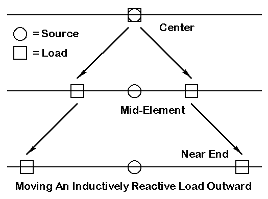
Let us take the #8 model and place the loads successively 10% further outward from center. In terms of total antenna length, this amounts to placing the load at the 45%-55% positions, the 40%-60% positions, etc. For a 91-segment dipole, we can only approximate these positions, but the results are certainly close enough to reveal the trends involved. The exercise can use simple R +/- jX loads. At each position, we increase the value of inductive reactance to bring the dipole to within +/- 1 Ohm reactance of resonance at 7.15 MHz.
Initially, we can let the Q of the load be indefinitely high (or infinite, meaning resistively lossless) by setting the value of the load resistance to zero. We obtain the following table of results.
Position  Position       Reactance in   Source Impedance    Free Space
Approx %  Actual %       Ohms per Side  R +/- jX Ohms       Gain dBi
 5/95      4.95/95.05    3948           37.7 + j 0.3        1.91
10/90     10.44/89.56    1939           34.4 - j 0.5        1.90
15/85     14.84/85.16    1369           32.0 + j 0.4        1.89
20/80     20/33/79.67     996           28.9 + j 0.8        1.88
25/75     24.73/75.27     817           26.5 + j 0.8        1.87
30/70     30.22/69.78     668           23.6 - j 0.6        1.87
35/65     44.62/65.38     586           21.3 + j 0.7        1.86
40/60     40.11/59.89     510           18.4 - j 0.5        1.86
45/55     44.51/55.49     465           16.2 + j 0.7        1.86
50/50     50/50           416.65        13.2 - j 0.0        1.85
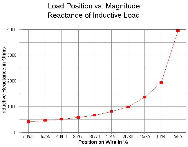
The most significant trend to note is the steady rise in the required reactance to bring the dipole to resonance as the load is moved progressively outward from center. The following graph shows the trend with some clarity.
The source resistance and gain figures are predicated on the unlikely event of obtaining a perfect (lossless) inductively reactive load. A more realistic value would be a Q of about 300. This requires that for each load, we divide the reactance by 300 to obtain a series resistance for the total load. If we insert the required values of resistance into our R +/- jX loads, we obtain the following values at 7.15 MHz with our #8 lossless wire model. (Reactance values do not change and are not shown below.)
Position  Series R  Source Impedance    Free Space     Inductance
Approx %  Ohms      R +/- jX Ohms       Gain dBi       microH
 5/95     13.16     57.4 - j 0.9        0.08           87.9
10/90      6.46     44.7 - j 0.9        0.77           43.2
15/85      4.56     39.6 + j 0.2        0.96           30.5
20/80      3.32     34.9 + j 0.6        1.07           22.2
25/75      2.72     31.6 + j 0.7        1.11           18.2
30/70      2.23     27.9 - j 0.7        1.13           14.9
35/65      1.95     25.2 + j 0.6        1.13           13.0
40/60      1.70     21.9 - j 0.5        1.12           11.4
45/55      1.55     19.6 + j 0.7        1.02           10.4
50/50      1.39     16.0 - j 0.2        1.02            9.3
The inductance that yields the required reactance is shown in the right- most column for convenience, and we shall return to it in a moment. First, however, let us look at the values from left to right. The series resistance values can be compared to the reactance values in the preceding table to confirm a Q of 300. The other values may benefit from a bit of graphing.
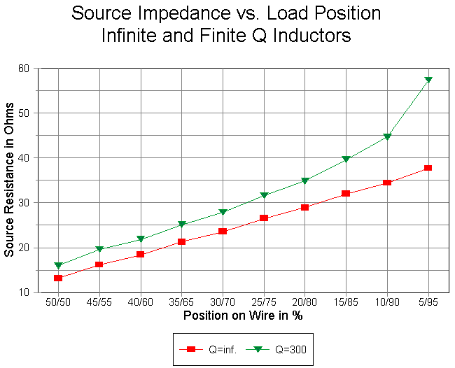
The source resistance increases approximately, but not exactly, as the loss resistance increases for each pair of loads. The small differential between the reported source resistance and the sum of the source resistance with an infinite Q and the total of resistive losses results from placing the loads ever farther from the center or source point of the dipole. Nonetheless, the trend is abundantly clear.
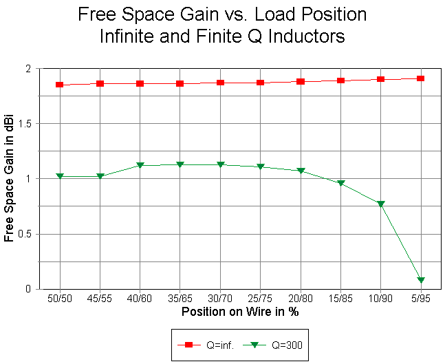
The graph that compares the free space gain of the dipole without load losses and with losses of a Q=300 load is perhaps more interesting. The lossless loads show a wholly insignificant variation of gain, regardless of load position. However, with a Q=300 load, the gain of the dipole shows a rise of 0.1 dB when the loads are place 20% to 60% of the total element length each side of center outward from the center--relative to the gain with the load centered. Beyond the 60% mark (20/80%, in terms of total dipole length), the gain decreases severely and rapidly as a result of the equal rapid increase in resistive loss that goes along with the steep rise in required loading reactance.
The 0.1 dB gain differential between center and mid-element loading is of questionable operational benefit. In a horizontal dipole, the use of mid-element loading in preference to center-loading is for other reasons, most often the higher source resistance of the dipole with mid-element loading. There remains a persistent myth that mid-element loading shows significantly higher gain than center loading. This myth derives from short mobile antenna experience using loaded monopoles. Field strength differences resulting from the environment within which such antennas work and from the very short lengths they use have become unwarrantedly generalized to cover all antennas making use of inductively reactive loads.
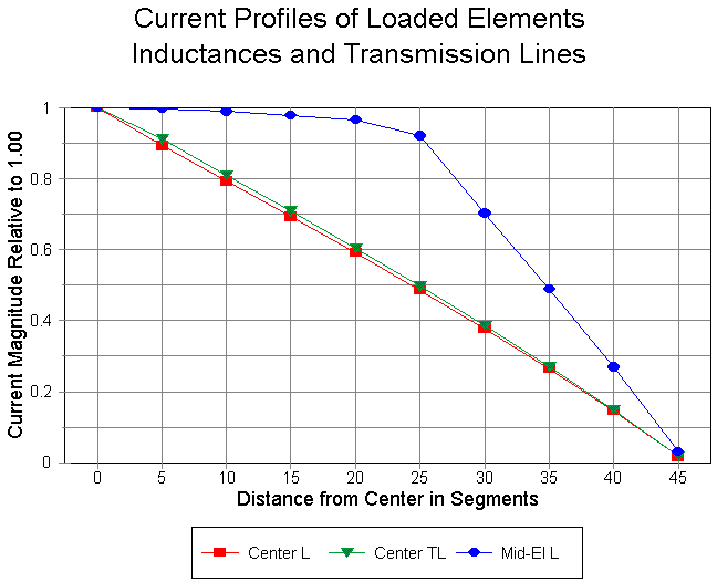
A second source of the myth is an uncritical examination of current magnitude curves along loaded elements. The graph above displays the current magnitude for the R-L-C center-loaded element, the TL near-center-loaded element, and the mid-elemented R-L-C loaded element. Seemingly, the current magnitude (relative to a source value of 1.0) indicates a stronger far field based on the assumption that the field is roughtly proportional to the current. However, that assumption needs considerable modification with loaded elements.
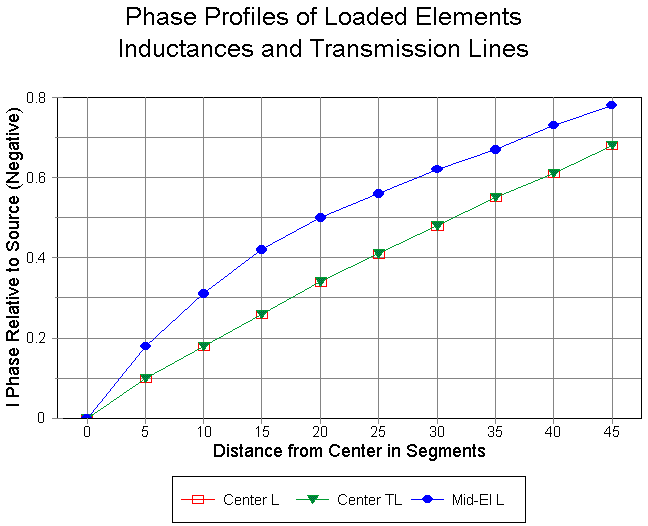
One modification is occasioned by the current phase change along the element. For the mid-element loaded model, the rate of phase change along the element is much higher than for either center-loaded model. Moreover, the current magnitude curve is not a direct measure of the undisipated power in the element.
Using the strictly mathematical models of loads of all sorts, we may replace the Type 4 loads with either series R-L-C loads or with transmission lines (TL networks). (Note: as in the preceding episode in this series, we are purposely violating the injunction against using TL loads where current meagnitude on the two lines is unequal in order to study the effects of trying to model with them.) The right-most column of the table shows the equivalent inductance values for the reactance loads used in this exercise. Although the weight and gain drop associated with such large inductance values is reason enough not to place loading inductors at the far ends of antenna elements, there is another reason as well. In at least the most extreme case (87.9 microH), for any practical single-layer solenoid coil-winding technique, we would not reach the required inductance before the antenna had passed resonance and had begun to show an inductive reactance at the source. We shall return to this point in a later episode.
Although certainly precise enough to show the important trends associated with mid-element placement of loads, the technique of choosing segments on which to place loads was only approximate. Except at the very center of the dipole, the loads were a bit off their desired marks.
We could so segment the dipole that the loads would appear (as centered on their segments) in the desired places--but only for this exercise. If we chose other percentage values for load placement, further revisions of segmentation would be required. There is an alternative.
Consider the following problem (which, for the moment is academic only): suppose we wish to find the places along the dipole element where each of two mid-element loads are identical in required reactance to a single center load. For our 1/4 wl #8 perfect wire dipole, the required reactance of a center load is 833.3 Ohms to achieve resonance at 7.15 MHz. The question then is where along the wire to place two 833.3-Ohm loads also to achieve resonance.
The model has 91 segments. If we place the loads on segments 23 and 69, the source impedance reports as 27.11 + j 31.7 Ohms, which indicates the loads are too far inboard. If we place the loads one segment further outward--on segments 22 and 70--the source impedance reports as 26.34 - j 39.04 Ohms, which indicates that the loads are too far outboard. Within the limits of the model, neither placement satisfies the requirement of achieving resonance within +/-1 Ohm.
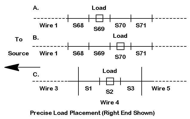
These unsatisfactory situations are indicated in parts A. and B of the figure above. The figure also indicates an alternative modeling method that permits precise load location without sacrificing model accuracy. The model in C. is a 5-wire model, all composed of the same type of wire. Two outer sections and a center section are long wires having many segments. Two special wires have 3 segments each, with the load placed on the center segment.
The use of 3 segments on the load wires serves to ensure that the segments immediately adjacent to the load segment are equal in length to the load segment. The center wire and the outer wires are segmented so that each segment length is as close as possible--within the limits of the total segmentation of the antenna--to the length of the load wire segments.
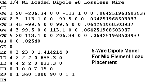
The .NEC model above shows the dimensions of the final model in terms of the wire geometry for the dipole with Type 4 reactive loads. For the #8 wire model, a center wire 199" long (+/- 99.5") used 45 segments, each 4.42" long. The outer wires are each 94.24" long and use 20 segments, each 4.71" long. The 3-segment load wires are 13.6" long, with segments 4.53" long. The total number of segments for the antenna remains 91.
The loads are centered 106.3" each side of the source. With this configuration, the reported source impedance is 26.78 + 0.53 Ohms, well within the limits set for resonance. The figures are for a pure reactance, with no series resistance.
The technique used here is subject to many variations, including resegmentation to achieve even closer segment length equality along the antenna. Even more precise placement is possible to achieve resonance within narrower limits (for example, +/- 0.1 Ohm). However, for the purposes of this demonstration, the techniques used are sufficiently precise for both placement and resonance.
Having placed the 833.3-Ohm load correctly at mid-element positions, it useful to take a preliminary look at the performance curves that result from applying the equivalent Type 0 (series R-L-C) load at both center and mid-element positions. The inductive equivalent of 833.3 Ohms at 7.15 MHz is 1.8549E-5 H. We can look at the curves both for infinite Q and for some representative Q, say, 300. The series resistance required for a Q of 300 at the design frequency is 2.778 Ohms.
Once more, we shall use our #8 lossless wire 34.39' dipole.
#8 Wire Dipole           Source Impedance (R +/- jX Ohms)
Freq.     Center Load    Center load    Mid-El. Load   Mid-El. Load
MHz       Q=inf.         Q=300          Q=inf.         Q=300
7.00      12.58-46.28    15.35-46.29    24.33-82.17    29.07-82.25
7.05      12.78-30.76    15.56-30.76    25.11-55.15    29.98-55.23
7.10      12.98-15.30    15.76-15.31    25.93-27.54    30.94-27.64
7.15      13.19-0.02     15.97-0.02     26.78+0.53     31.93+0.40
7.20      13.40+15.26    16.18+15.26    27.67+29.19    32.98+29.08
7.25      13.61+30.25    16.39+30.25    28.60+58.35    34.07+58.54
7.30      13.82+45.29    16.60+45.29    29.58+87.98    35.21+87.84
Delta R    1.24          1.25           5.25           6.14
Delta X   91.57          91.58          170.15         170.09
Mid-element loading results in a larger swing of both source resistance and source reactance across the span of frequencies swept in this exercise. The result for resistance is larger not only in terms of Ohms, but also when taking the swing as a percentage of the design center frequency value. The result for reactance, however, is the opposite: as a percentage of the design center frequency resistance, the reactance swing is smaller for the mid-element load case than for the center loading case. Moreover, for the mid-element loads, there is not the virtual identity of swings for either resistance or reactance that holds over the frequency span swept by the models with center loads.
The smaller change of reactance relative to the resonant source resistance also suggests that the SWR curves for the mid-element loading cases might be broader than for their center-load counterparts. Of course, SWR is plotted relative to the design center frequency resistance value, where the antenna is resonant within the prescribed limits for this exercise.
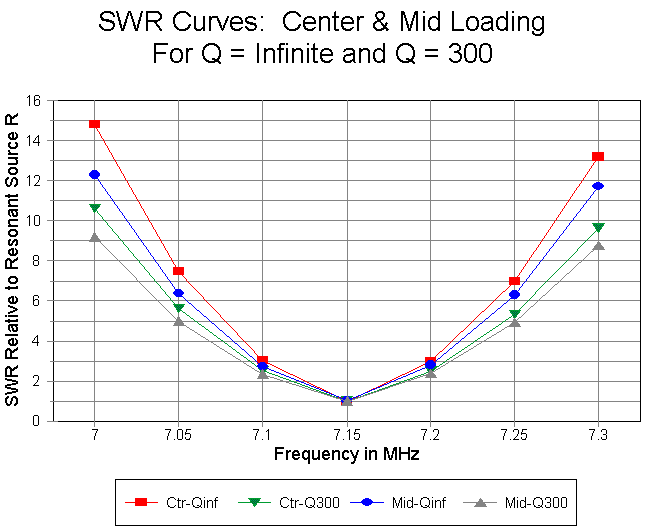
The graph confirms our suspicions. The upper two curves are for the test runs at an indefinitely high Q, while the lower curves are for the value Q=300. In both pairs, the curve for the mid-element loaded dipole is broader than its center-load counterpart. Two cautions attend these curves. First, the effect of wire losses are not accounted within the overall curve, since we are using perfect wire in order to isolate, as best we can within the model, the phenomena that may ascribed directly to the load itself. Second, the conditions of modeling must be remembered: the model is a free space model that, of course, does not take any ground effects into account. The modeled loads assign both the series resistance and reactance and do not take into account any further effects that might accompany a real single-layer solenoid inductor placed in center or mid-element loading service. Although specified in a Type 0 load in terms of a series combination of resistance and reactance, the loads are strictly mathematical entities whose physical properties are not calculated in the overall antenna evaluation.
The antenna free space gain for the various cases corresponds well to the curves earlier presented. The infinite-Q antenna shows a gain of 1.85 dBi for the center-loaded case and 1.87 dBi when mid-element loaded. When each loading inductor is set at a Q of 300, the gains are 1.02 dBi and 1.11 dBi, respectively. Again, these gain figures do not include any wire loss associated with the main element.
While we are exploring these modeling curves, we might as well compare transmission line loading when placed at the same mid-element point with the case developed in Part 1. In that instance, we placed a split load in the segments immediately adjacent to the source segment, because placement exactly on the source segment would not have yielded valid series load results. Even that small move of the load position required that we use two 426.3-Ohm loads, rather than a pair of 416.65-Ohm loads (833.3/2). The resultant 600-Ohm (velocity factor = 1.0) transmission line stubs were each 13.52' long. To replace the mid-element 833.3-Ohm loads with transmission line stubs with the same characteristic impedance requires lengths of 20.73' each. Once more, remember that transmission lines used in NEC models are lossless and mathematical. Within those constraints, the results are as follows:
#8 Wire   Source Impedance (R +/- jX Ohms)
Freq.     Near-Center    Mid-Element
MHz       Placement      Placement
7.00      13.09-52.66    23.84-110.0
7.05      13.31-35.04    24.76-74.67
7.10      13.53-17.46    25.74-37.85
7.15      13.76-0.03     26.78+0.42
7.20      13.98+17.57    27.90+40.47
7.25      14.21+34.88    29.09+82.25
7.30      14.44+52.30    30.38+126.0
Delta R    1.35          6.54
Delta X   104.96         236.0
The mid-element transmission line load source impedance value verifies that the transmission line stub is the correct replacement for the reactance load of 833.3 Ohms. However, even with a 600-Ohm transmission line, the variance of reactance across the band is very large. As we have noted, with transmission lines of lower impedance, the variance will be larger still.
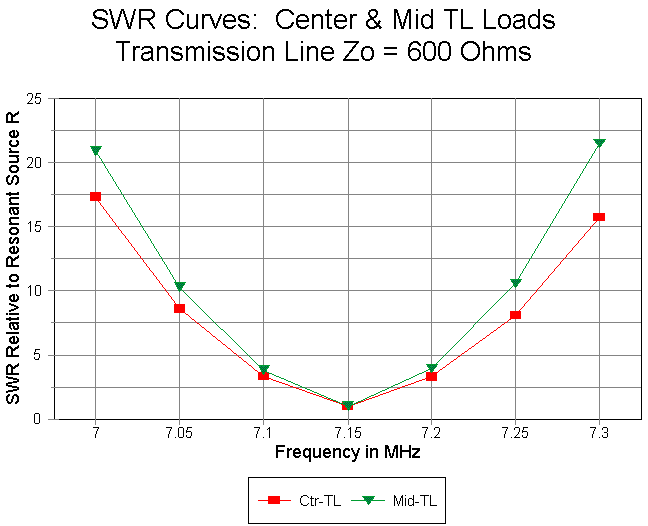
Comparing the SWR curves (relative to an SWR of 1:1 at resonance) for the near-center and the mid-element transmission line loads shows an interesting result that is opposite to results from using series R-L-C loads. The mid-element loading stub system yields a narrower SWR curve than the near-center loading system. This consequence follows from the much high values of reactance required of the stub. Since the reactance of the stub is a tangent function of the electrical length of the stub, stubs over 45 degrees long change their reactance values rapidly. The required stub length in this case is 54.2 degrees.
Commonly, series R-L-C loads are considered to be adequate models of single-layer solenoid inductor performance in a loaded dipole or similar element. Despite their strictly mathematical nature, that is, the fact that their physical structure does not play a role in the calculation of predicted antenna performance, the resulting antenna performance figures are considered accurate enough for most practical design and analysis purposes. The key loss factor in a solenoid inductor is the series resistive loss, and other losses and factors that might cause variations from the predicted outcomes are considered too small to be of significance. Consequently, only in the most critical cases are solenoid loading coils physically modeled--and usually only where such coils are very simple. An example of such a case is the solenoid in the middle of many automobile UHF antennas for cellular telephone service.
Transmission line loads, on the other hand, are widely distrusted as models of linear loads used in HF antennas. Most obviously, they do not permit the accurate introduction of resistive losses in the transmission line. Nor do they permit, except as an external calculation, the introduction of the line's velocity factor. (Some programs permit velocity factor information to be introduced into the interface between the user and the core calculation, subsequently converting it to the values needed by the core's network calculations.)
Most antenna's employing linear loads use load wire having a diameter different from that of the main element. Although MININEC can directly handle these types of models, the required model often presses the segmentation limit of the program. (Some recent MININEC developments, such as NEC4WIN, have broken the 256-segment barrier, and one version permits virtually unlimited numbers of segments, but at the cost of slow calculation speeds.) MININEC has additional requirements in order to reduce errors at sharp corners, NEC (in either version 2 or version 4) is inaccurate when faced with angular junctions of wires having dissimilar diameters. Consequently, physically modeling existent antennas with linear loads is not normally attempted.
However, it is possible to physically model linear loads using a uniform wire diameter throughout the model. While the technique does not yield an accurate model of a particular antenna, it does produce quite accurate results that can reveal some interesting properties of linear loads. The technique may also permit some preliminary sorting of different functions performed by a linear load and the conditions under which it performs them. Physically modeling some linear load configurations will therefore be our next task.