In the first four sections of this series on inductively reactive loads used to electrically lengthen physically shortened antennas, we uncovered some interesting disparities between the standard mathematical models of loads and loads which are physically modeled. If the demonstration models are valid, then the following summary points are true in principle.
1. Because the current magnitude and phase in a transmission line used to load a short antenna do not show a true transmission line relationship in a physical antenna, the use of the TL facility in NEC is not a reliable model of the real line and should be confirmed with a physically modeled transmission line load.
2. Linear loads are a variety of transmission line stub load, but their behavior should be physically modeled for greatest reliability, especially when folded back from a mid-point along the so-called main element. Within the length of the linear load, which wire comprises the "main" element is ambiguous, since the radiation from that portion of the antenna is a function of the closely coupled fields from the element and the load wires in the stub.
3. To a lesser but still significant degree, physical models of single layer solenoids, when modeled as helices, depart from the Type 0, 1, and 4 NEC mathematical models of them when placed as loads along an antenna element. In general, such loads show composite properties as inductances and as added wire length, the latter of which properties contributes to the radiation field of the antenna. The effect increases as the inductors are moved outward from the center of a dipole, with less inductance being required for the load than for a center loading coil. Even a center loading coil requires less inductance in physical models than called for by the NEC mathematical load.
Although the exercises have demonstrated the effects, they fall far short of establishing a set of universal principles, mostly due to the limitations of NEC. Some of the potential error sources in NEC-4.1 have been reviewed in "NEC-4.1: Limitations of Importance to Hams," QEX (May/June, 1998), pages 3-16.
Throughout the exercises, NEC-4.1 was used in the EZNEC Pro and the Nittany-Scientific GNEC implementations. In all models, unless otherwise specified, the linear wire was modeled as lossless in order to sort out losses and performance curves due to the load from those attributable to the linear wire. Hence, all gain figures in previous exercises will be higher than with any real antenna using copper or aluminum elements. All models were constructed in free space.
The model short dipole for 7.15 MHz was 1/2 full size at 34.39' (412.7") long and used #8 AWG (0.1285" diameter) wire. All physically modeled load structures used the same wire in order to avoid possible errors resulting from angular junctions of wires having dissimilar diameters. The original antenna was assigned 91 segments, each about 4.53" long. The selection of segment length served a number of purposes. First, it set the spacing of linear load wires from each other at a reasonable distance for accurate modeling. Second, it permitted the construction of octagonal single layer solenoid inductors that were exactly 3 segments long and whose wire lengths for each portion of each turn were close in length to the adjacent segments of the linear wire.
The original model was revised for mid-element loading exercises into a 5- wire model. 3-segment wires were placed on each side of the center wire so that the center segment of the insert was positioned exactly where a mid- element load was equal in size (reactance and inductance) to a corresponding center load such that either system brought the antenna to resonance with no change in the overall length of the dipole. The overall segmentation was not changed, so that segment length among models remained close to equal. A 3-segment long (13.6") physical inductor model replaced the center 3 segments of the model for center loading and replaced the two inserts for mid-element loading tests.
Subject to continuing review, it is believed that these models fall well within the limitations of NEC-4.1's ability to provide accurate results. It should be unnecessary to add that the relationship of the NEC-4.1 modeling system to real antennas is not like the relationship of a child's plastic toy to a real automobile. Rather, NEC-4.1 (and other versions of NEC and MININEC) are complex mathematical systems based upon both fundamental antenna theory and fundamental mathematical principles for calculating the various performance parameters of many types antennas. Those who dismiss antenna modeling in general largely reveal only a general lack appreciation of the role of mathematics in both antenna theory and antenna practice.
Those who develop, implement, and work with any version of NEC are also conscious of its limitations. All version of NEC have been extensively tested against experimental results for many fundamental antenna types. However, it is possible to create antenna geometries that exceed the limitations of the calculation system. In such cases, NEC yields results that do not tally with either theory or practice. Since no program developer or development team can fully predict all of the antenna geometries (or environmental circumstances) that users will model, they can only enumerate some of the program limitations. Users will discover other limitations in the course of their work, and these limitations set the challenges for further development.
This note is about some of the limitations that apply to the extension of the models used in this exercise set to various real antenna designs.
The difficulty of extending the models used for linear loads in these notes to real antennas can best be illustrated by taking up a few concrete examples of extant antennas.
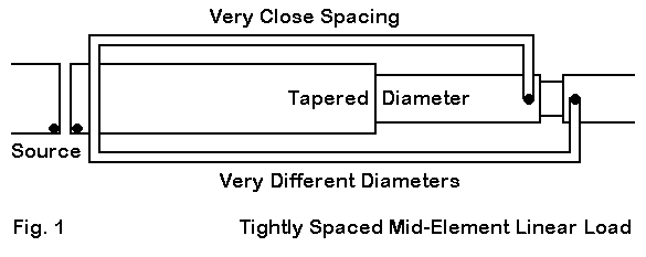
Fig. 1 shows a sketch that outlines the basic design features of one commercially manufactured antenna element using a linear load. To this point, I have been unable to construct a model of this element that falls within NEC limitations.
The element uses a series of tubes of decreasing diameter as one moves from the center point outward. The NEC-2 limitation with tapered diameter elements is largely, but not completely, overcome in the NEC-4.1 algorithms. Modeling this element in NEC-2 with Leeson corrections (or, more properly, conversion of the element into its equivalent uniform diameter equivalent) is not possible, since the linear load junctions would block correction implementation (and the implementation of the correction would be inaccurate, since the element is not continuous).
In this particular design, the linear load wires are very thin compared to the center element, and they are very closely spaced to the center element. All versions of NEC yield erroneous results when wires of different diameter are closely spaced. Moreover, there is a right-angle junction of wires of different diameter, another case in which NEC yields erroneous results.
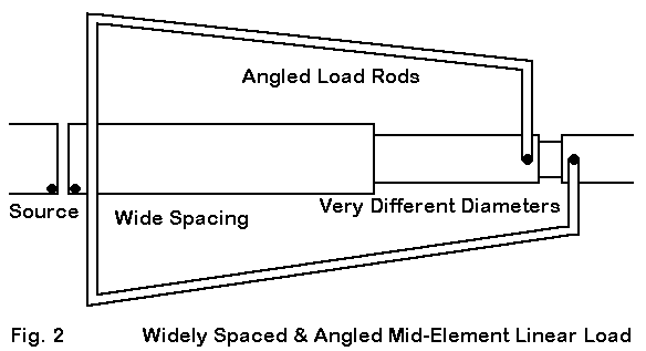
A second design of commercial origin appears in Fig. 2. In this case, the previously noted limitation involving angular junctions of wires having dissimilar diameters also applies to this design, since the load wires are very much thinner than the center element tubing. The tubing also uses a diameter tapering schedule, adding a definite limitation to modeling with NEC-2 and a minor limitation for NEC-4.1.
The wires of the load are not parallel to each other. This feature would make the correlation of the load to transmission line stubs more complex, although for general purposes, the averaged characteristic impedance of the line might be used with fair accuracy. However, to the degree that physical models of parallel transmission lines yield results at variance form standard calculations, determining the characteristic impedance of the physically modeled line will prove more difficult.
A third feature of this design is the placement of the long shorting bar near the center of the element. Physical models of shorted transmission line stubs take into account the current magnitude and phase of the shorting bar. In this instance of a long bar, the bar itself becomes an integral part of the line, one having a rapidly decreasing spacing between opposing segments. The design also may place the shorting bar at a distance from the element center point than used in the exercise models. Hence, the correlation drawn in the exercise between mid-element loads folded back to the center and loads properly called center linear loads may be less certain for this case.
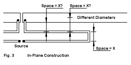
We can illustrate the difficulties of modeling a real linear load in NEC by looking once more, in Fig. 3, at the model of the in-plane center linear load, discussed in part 3. In that model, using #8 wire uniformly throughout the model, several facets of real antenna construction were simplified. The spacing between the three wires was set at 4.53" center-to-center. This spacing produced identical surface-to-surface spacings that were 0.1285" less than the center-to-center spacing.
If we increase the "main" element to a 1" diameter, center-to-center spacings no longer correlate to surface-to-surface spacings, changing the relationship among the elements. In addition, we encounter the potential problem in NEC of closely spaced wires with different diameters.
Fortunately, this model just barely fits within the MININEC segmentation limit and can be evaluation on that system. MININEC does not show a limitation with respect to closely spaced wires with different diameters. However, MININEC models tend to clip corners with angular connections, and we should expect (without invoking length tapering) some required change in the length of the loading wires if we hold the overall length constant.
The following table shows the results of modeling the in-plane antenna in both NEC-4.1 and in MININEC. Load line lengths (from center to short) are given to indicate the require modifications to achieve a value close to resonance (in this demonstration, loosely defined as under +/- 5 Ohms). In addition, values are shown for models using lossless, copper, and aluminum wire throughout.
                         MININEC                       NEC-4.1
Main                Free Space     Feed Z         Free Space     Feed Z
Element             Gain dBi       R+/-jX         Gain dBi       R+/-jX

#8 AWG                   (Load = 194.5")               (Load = 188")
  Lossless wire     1.85           11.9-j1.2      1.79           12.1-j0.0
  Copper            1.30           13.5-j1.2      1.25           13.7+j1.5
  Aluminum          1.04           14.3-j1.2      0.99           14.5+j2.4

1"                       (Load = 158")                 (Load = 165.3")
  Lossless wire     1.85           11.9+j4.5      1.25           13.7-j0.5
  Copper            1.39           13.2+j4.5      0.83           15.1+j0.9
  Aluminum          1.17           13.9+j4.5      0.62           15.9+j1.6
In the table, gain figures are shown to 2 decimal places in order to show numerical trends that would have been erased by excessive rounding. (For operational purposes, figures to a single decimal place would suffice for many comparative cases, and the decimals might be dropped from certain generalized discussions. However, those who believe that showing gain to multiple decimal places should be dropped in all cases simply lack an appreciation for all of the purposes for which the antenna modeling programs can be put to effective use. Each degree of precision in reportage has its proper context. My own preference would be to see modeling reports overly precisely reported and then to do my own rounding than to see such figures prefiltered.)
The gain and impedance figures for the #8 model show excellent correlation between the modeling systems, with a maximum gain variance of 0.05 dB and a maximum resistive variance of 0.2 Ohms. If we look at the MININEC column and read downward, then the reported performance of the 1" main element version of the modeled antenna shows very sensible results. The lossless version of the model shows minuscule differences from the #8 version (actually none in the truncated decimals used here). The copper and aluminum versions of the 1" version show increases in gain over the #8 version as the material becomes more lossy. This is a function of the increased surface area of the larger element, and a similar trend shows up in full size dipoles. Likewise, the feedpoint impedance of the 1" antenna decreases more rapidly from the #8 version as the material loss increases, again for the same reason of lower overall losses. Once more, this trend also shows itself in unloaded antennas.
Regardless of the absolute accuracy of the MININEC figures, the trends in numbers are not only intuitively sensible, they correlate with the behavior of models of unloaded antennas. In contrast, the NEC-4.1 figures for the 1" diameter main element model report decreases in gain and increases in feedpoint impedance for each material assignment. These numbers indicate either that the wire spacing for the element sizes involved and the frequency of test (7.15 MHz) has crossed the threshold at which NEC-4.1 no longer delivers accurate results or that the angular junction of the #8 wire with the 1" wire is yielding less than accurate results--or both. It is common in either error mode for NEC to report a gain that is too high/low while reporting an source impedance that is too low/high.
Allowing for corner junction errors, MININEC remains the program of choice for modeling complex geometries that involve junctions of wires having dissimilar diameters and/or closely spaced wires of differing diameters. Recent developments in MININEC to break the segment limit, such as in NEC4WIN, will go far to make more complex MININEC models possible. However, not until the other MININEC limits are overcome--namely, raising the speed of matrix execution and grafting on the Sommerfeld-Norton ground calculation system--will the program be fully competent for all purposes.
In the physical models of single-layer solenoid inductances used as loads, the constraints imposed on the exercise dictated the use of helices with a relatively large diameter (11.85") and a long length (13.6"). The wire size (0.1285") was relatively thin compared to the turns spacing (1.36"), which yielded a coil Q somewhat less than the theoretical maximum for the overall configuration.
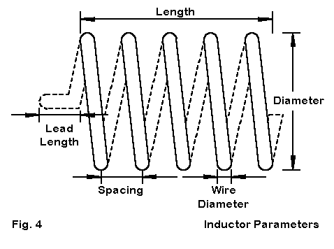
Fig. 4 shows some of the key parameters of coil construction that play a role in physical determination of coil inductance. Length, diameter and turns spacing are parts of the classic 1928 Wheeler approximation for single-layer solenoids (as found in ARRL Handbooks since almost time immemorial):

where L is the inductance in microHenries, d is the diameter, l is the length, and n is the number of turns, and where d and l are in the same units. The number of turns can be determined from the length and turns spacing (or vice versa). For coils used at upper HF and higher, the lead length becomes a significant factor in the coil's inductance. In antenna modeling, the lead length is generally absorbed by the linear element length.
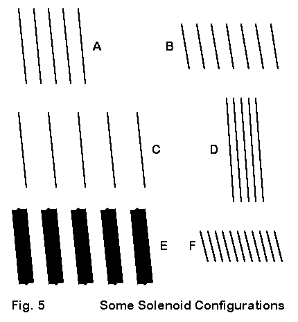
In Fig. 5, we find some variations on the coils used in the physical models. If we let A represent the coil configuration used, we might obtains the same inductance (and reactance) using a coil like that in B, which uses the same spacing, but a smaller diameter and more turns. C spreads the turns over a longer length, while D uses a shorter length, closer spacing, and a larger diameter, perhaps to effect the highest Q configuration that might be practical. E employs fatter wire to achieve a high Q by optimizing the wire-diameter-to-turn-spacing ratio. Each of the preceding variants on the original coil was based on theoretical factors. However, in practical antenna design, one might also accept a somewhat lower Q in order to achieve a design that slipped wind by virtue of its small diameter, as suggested in F.
Each coil configuration is likely to affect antenna performance slightly, due to different radiation field additions that depend on diameter and turn spacing. Some of the variants are more easily modeled than others. With proper attention to segment lengths, coils that use the same size wire as the main or linear element can be modeled with fair ease. However, length tapering of the linear element as it approaches the helix may be necessary for coils with small diameters. Where coils use wire diameters that differ from that of the main element, NEC (in any version) will exhibit a tendency toward erroneous results.
The consequence is that modeling solenoids as physical loading elements in an antenna may not in all cases be practical, although the task itself may become design-specific, especially in view of all of the variations possible. Thus, it may be some time before there is a more general profile of the affects of coil design on the performance of shortened antenna elements that use them. However, whatever differential there is between a physical coil and a mathematical load will apply equally to both NEC and MININEC, since both use essentially the same mathematical loading schemes, allowing for the fact that NEC places the load on a segment and MININEC places a load on a pulse or junction of segments.
It is perhaps a curiosity (since multiple types of coils have not been checked) that the loading coil used as the center load in part 4 of this series--and also used as the mid-element load--can be trebled to yield a 30-turn helical dipole only 40.8" long by less than 12" diameter. The resonant frequency of this experimental design was 7.105 MHz, only slightly lower than the standard design frequency used throughout the demonstration. If the exercise has any utility at all, it lies in the confirming the soundness of the advice to model solenoids using the material that will actually form the coil.
Material            Free Space          Feedpoint Impedance
                    Gain dBi            R +/- jX Ohms
Lossless wire        1.76               0.3 + j 0.5
Copper              -5.46               1.3 + j 1.6
Aluminum            -6.99               1.9 + j 2.2
The impracticality of the design, as indicated by the source impedance, is less important than a comparison of the anticipated gain of the antenna from the lossless wire to normal materials. Lossless wire makes the antenna look like a promising performer, while the gain figures for real materials tell the true story. There is no magic in this system. Indeed, it packs over 93' of wire into the helix, more than required for a standard 40-meter dipole. Yet, at 7-9 dB below the performance of a full size dipole, signals would be down by only about 1.5 S-units. Such performance would be usable under certain kinds of operating conditions, although the losses associated with feeding the antenna might attenuate signals even more than the basic design itself.
Obviously, those interested in helical antennas will always benefit from making them as long and open as possible. An adequate model of a helical monopole or dipole will always take the form of a physical model.
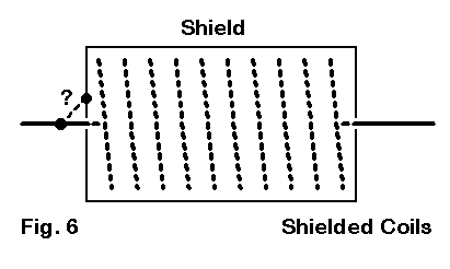
One final note on solenoids seems necessary, based on Fig. 6 above. A common practice, especially in commercial antenna manufacture is placing a solenoid within a shield, and the shield may be connected (or not) to either of the linear wires extending from it. At present, I am unaware of any technique of modeling this situation which has been correlated to experimental results. One can surround the solenoid with a series of wires or even a wire grid--with one end connected to an antenna wire if desired. To what degree antenna fields arising from the solenoid will interact with the shield and what the consequences for the overall antenna field will be remains an area yet to be fully explored. It, too, is likely to remain a project-specific task for antenna designers. If we add in the variables of coil construction that might be present within the shielding structure, the task is no small one. Note that the term "shield" is here used by convention. To whatever degree that casing plays a role in radiation field production, it shielding effects may be only mechanical. Its electrical role may turn out to be either simple or complex.
These notes are intended to provide a reasonably fair view of the limitations of the modeling studies undertaken in the first 4 parts of this series. They provide some cautions against taking the results of the work as numerically general principles, which they are not. They also caution against hasty modeling that might unwittingly cross the boundaries of NEC capabilities. Finally, they also outline a host of work that might be done to extend the study and to make its conclusions both more general and more precise.
Some of the further work can be done with some modeling ingenuity. Other parts of the work might be undertaken in alternative programs, such as MININEC. However, there may be a residue of the effort that may have to await the next generation of modeling cores.