We have mentioned the use of the NEC TL facility along the way, but perhaps a concentrated dose of TL might get us better oriented to using mathematical transmission lines in NEC. Note that this facility is not available in public domain versions of MININEC.
First of all, let's look at the rules for when it is apt to use transmissions lines and what their limitations may be. The TL input for NEC (-2, -3, -4) is a special form of network input, designed specifically to enable modelers to place transmission lines into a model. Since we are dealing with a network, we must have two wires on which to place the ends of the line we create.
For applications where the line connects two antenna elements, the requirement for 2 wires poses no problem, as shown in Fig.1, part B. However, when we wish to connect a transmission line to a source to see the effects of line length on the impedance or when we wish to use transmission line stubs as reactances, then we must create the second wire, as shown in Fig. 1, Part A.
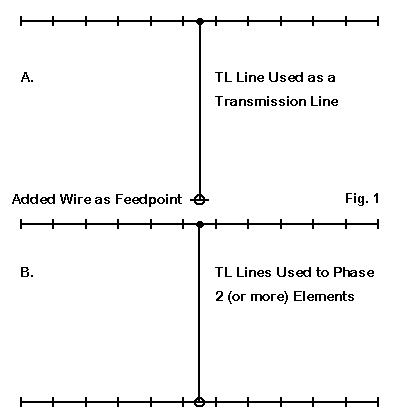
For the types of cases just noted, the second wire should be positioned and sized so that it plays no significant role in the far field of the antenna itself. This requirement forces the wire to be at some considerable distance from the antenna--the farther the better. Moreover, the wire should be thin and short--a single segment wire just meeting the lower limits of radius and length works fine. The wire should itself be lossless, if that option is available.
The position of the terminating wire makes no difference to the length of the transmission line in the mathematical model. The user will always specify the length of the transmission line, and this value will supersede the distance created by the modeled placement of the terminating wire.
The user will specify the segments of wires which represent the terminal points of the transmission line. As well, the user will specify the length and the characteristic impedance of the line. The basic length is the electrical length, assuming a velocity factor of 1.0. Some programs allow the user to specify the physical length and the velocity factor: the program then uses those numbers to calculate the electrical length for actual NEC calculations.
Since the line created by the TL entry is mathematical only, the line itself plays no role in the generation of the antenna's far field. This feature may be a modeling convenience in many cases, but in some other cases, it may represent a limitation on the model. If the transmission line plays a role in the antenna pattern, as is the case in many off- center-fed wire antennas, a physical model of the transmission may be preferable to use of the TL facility.
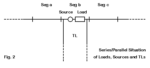
Sources and loads on the same segment appear in series with each other. TL entries are different. They appear in parallel with sources and loads that are placed on the same segment, as shown in Fig. 2. This factor must be kept in mind when trying to add a TL transmission line to a source segment that is already loaded. This feature is both a limitation and an opportunity--as we shall see further on.
Since TL transmission lines are mathematical, they show no losses. If you wish to know the losses involved in a transmission line application, you must hand calculate them or use other software, such TL by N6BV. These calculations may also reveal slight differences in the 2:1 SWR bandwidth of some models relative to the lossless line in the model.
The TL line will be accurate only if applied under balanced conditions, that is, where the current on each side of the line is the same. This restriction dictates that TL lines be used at such places as the center segment of a linear horizontal element. Applying a TL line off center will yield inaccurate results. Theoretically, one might apply a TL transmission line as a phasing section between two collinear dipoles. However, the current and voltage at the junction point are changing so rapidly that equalized currents are rarely feasible. For such applications, modeling a physical parallel transmission line is advisable.
How to Implement TL Transmission Lines
Depending upon the level of user help in a given implementation of NEC, the user may have to do little calculation--or a lot. EZNEC, for example, allows you to specify the two ends of the line--and offers preset options if you wish a shorted or open stub. These option eliminate the task of specifying a new wire in the model that represents the TL termination, since the program automatically generates the distant wire. For a shorted stub, the program specifies a very low resistance value as a load on the far wire--perhaps 1E-10 Ohms. For an open stub, the program loads the wire with a very high value of resistance, perhaps 1E10 Ohms.
With raw NEC and some programs, you must introduce the stub-terminating wires as added wires in the model description. Some programs require that you give them tag or wire numbers over a certain value so that they will not appear in views of the antenna.
You must then specify the characteristic impedance of the transmission line being mathematically simulated. EZNEC permits the entry of a velocity factor, and it also has a catalog of common transmission lines with their associated velocity factor values. Other software will require that you enter the electrical length of the line as well as the characteristic impedance. If this requirement applies to your software, you may simply divide the physical length by the velocity factor to determine the electrical length. Use care: even though you may have entered the antenna geometry in inches or feet, some programs will require that TL lengths be entered in meters, thus requiring one more conversion before finalizing the entry.
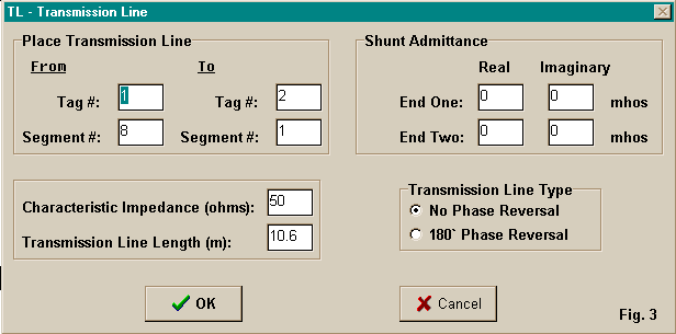
Fig. 3 shows a data entry box where no short-cuts are available. Here, standard NEC language is used. The "Tag" numbers are the wire numbers in the wire description portion of the model description, while the segment numbers are referenced to the segments themselves and not to percentages of the way along a wire. Hence, you must be careful to identify the correct segment number for exact placement of the TL. If you change the segmentation of the wire, you must return to this box and change the segment number for the TL on that wire if you wish it to be placed at a certain position, for example, at the wire center.
The line characteristic impedance is given as 50 Ohms, with an electrical length of 10.6 meters. This might represent 34.78' of line, if you did your original calculations in feet. If the velocity factor of the line is 0.66, then the physical length of the line would be only 22.95'. Be sure to keep records on paper of all calculations that lead up to NEC entries so that you can check your work later for errors.
The standard NEC entry for networks is in terms of admittance rather than impedance. Therefore, had we been building a shorted or open stub, we would need an entry here. A shorted stub would have virtually no resistance. In terms of admittance, we would insert a very high value, perhaps 1E10 mhos (now called siemens). An open stub would require a very high resistance and require a very low value of admittance, perhaps 1E-10 in the real column. For stubs, you may ignore the "imaginary" column, which would take values of susceptance, the inverse of reactance.
A Few Real Examples
To gain a better handhold on the use of TL transmission lines, let's look at a few examples involving real design questions. For this exercise, we shall use a few sketches and some model descriptions taken from EZNEC.
1. A 3-Element 15-Meter Yagi With a Quarter Wavelength Matching Section:
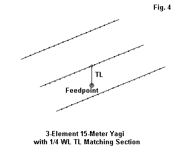
Fig. 4 shows the outline of a 3-element 15-meter Yagi of good performance (8+ dBi free-space gain and 26 dB front-to-back ratio at 21.2 MHz). The elements have been sized so that the antenna is resonant at the design frequency. The feedpoint impedance is 24.8 + j 0.4 Ohms, too low for a match to the standard 50-Ohm coaxial cable.
However, we can insert a 35-Ohm quarter-wavelength matching section to effect the match. To do so, we must add a 4th wire that is very short and of small diameter. Then, we add a quarter wavelength section of feedline according to the entry rules of the software we happen to be using. The line would be 11.6' or 3.54 m long electrically. If the velocity factor is taken into account, the line would be 7.655' long physically.
Below is the model description of the final arrangement:
3 el Yagi 3/4" el               Frequency = 21.2  MHz.

Wire Loss: Aluminum -- Resistivity = 4E-08 ohm-m, Rel. Perm. = 1

              --------------- WIRES ---------------
Wire Conn.--- End 1 (x,y,z : ft)  Conn.--- End 2 (x,y,z : ft)  Dia(in) Segs

1        -11.554,  0.000,  0.000        11.554,  0.000,  0.000 7.50E-01  21
2        -11.032,  6.991,  0.000        11.032,  6.991,  0.000 7.50E-01  21
3        -10.381, 15.074,  0.000        10.381, 15.074,  0.000 7.50E-01  21
4         -0.100,  6.991, -5.000         0.100,  6.991, -5.000    # 14    1

              -------------- SOURCES --------------
Source    Wire      Wire #/Pct From End 1    Ampl.(V, A)  Phase(Deg.)  Type
          Seg.     Actual      (Specified)

1           1     4 / 50.00   (  4 / 50.00)      1.000       0.000       V

No loads specified

                -------- TRANSMISSION LINES ---------

Line  Wire #/% From End 1  Wire #/% From End 1  Length       Z0   Vel Rev/
      Actual  (Specified)  Actual  (Specified)              Ohms Fact Norm

1     2/50.0  (  2/50.0)    4/50.0  (  4/50.0)    7.655 ft   35.0  0.66  N

Ground type is Free Space
The feedpoint impedance at the design frequency with the line in place is 49.4 - j 0.8 Ohms. Remember that TL entries are lossless, so there may be a small loss in the section that must be independently calculated.
Most interesting is the placement of the tiny wire (#4) used to terminate the transmission line and also to serve as the model source. I purposely placed it close to the antenna and vertically in line with the driven element. You should move this wire around in order to get some feel for how close or distant such added wires must be to have no significant effect on the antenna performance. In this case, the wire can be quite close without changing any of the performance figures. However, a distant wire placement is always in order.
2. A 4-Element 10-Meter Yagi With a Beta Match (Shorted Stub):
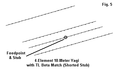
In Fig. 5, we have the outline of a 4-element Yagi. At 28.5 MHz, the design frequency, the antenna shows a free-space gain of 8.6 dBi with a 22 dB front-to-back ratio. The natural feedpoint impedance of the antenna is 25.8 - j 28.8 Ohms, a good candidate for a beta match. The simplest form of the standard beta match used to compensate for capacitive reactance is a hair pin or shorted stub having the correct inductive reactance according to standard L-circuit calculations. We can simulate the hair pin by creating a shorted stub of a reasonable characteristic impedance at the source junction.
For the model in this exercise, I used a 5" stub of 450-Ohm line with a velocity factor of 1.0. The EZNEC model description looks like this:
4 el 13' boom                         Frequency = 28.5  MHz.

Wire Loss: Aluminum -- Resistivity = 4E-08 ohm-m, Rel. Perm. = 1

              --------------- WIRES ---------------
Wire Conn.--- End 1 (x,y,z : in)  Conn.--- End 2 (x,y,z : in)  Dia(in) Segs

1        -103.73,  0.000,  0.000       103.731,  0.000,  0.000 5.00E-01  21
2        -97.942, 35.811,  0.000        97.942, 35.811,  0.000 5.00E-01  21
3        -97.226, 65.653,  0.000        97.226, 65.653,  0.000 5.00E-01  21
4        -91.078,152.195,  0.000        91.078,152.195,  0.000 5.00E-01  21

              -------------- SOURCES --------------
Source    Wire      Wire #/Pct From End 1    Ampl.(V, A)  Phase(Deg.)  Type
          Seg.     Actual      (Specified)

1          11     2 / 50.00   (  2 / 50.00)      1.000       0.000       V

No loads specified

                -------- TRANSMISSION LINES ---------
Line  Wire #/% From End 1   Wire #/% From End 1   Length     Z0   Vel Rev/
      Actual  (Specified)   Actual  (Specified)             Ohms Fact Norm

1    2/50.0  (  2/50.0)  Short ckt (Short ck)    5.000 in   450.0  1.00

Ground type is Free Space
In some software, you would need to create the distant wire for the shorted end of the TL stub and give it a very high admittance value. You may even have to convert the 5" length to its equivalent in meters.
With the stub specified, the feedpoint impedance is 43.4 + j25.2 Ohms, something less than a perfect match at the design frequency of 28.5 MHz. However, the stub length was not chosen for a perfect match at one frequency. Rather, the length was experimentally determined based on the goal of obtaining the widest 2:1 SWR operating bandwidth between 28 and 29 MHz. You should experiment with stub lengths (and characteristic impedances) to see the effects on SWR, both at the design frequency and across a desired band segment. Other values might easily improve on the operating bandwidth. You may also change the length of the driver to change the amount of capacitive reactance for which the beta match must compensate. The results may make full coverage from 28 to 29 MHz either easier or more difficult.
At a specific design frequency with the correct value of capacitive reactance to accompany the resistive portion of the feedpoint impedance, a beta match can be exceptionally efficient. However, as one moves away from the ideal conditions, small losses may accrue as the match must not only effect an impedance change, but must also compensate for non-ideal reactance values.
3. A 3-Element 10-Meter Phased Array With Director and a Beta Match (Open Stub):
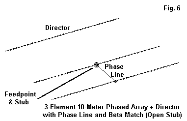
Fig. 6 presents two uses of TL transmission lines in one example. There is a reversed phasing lines between the rear 2 elements of the array. In addition, there is a beta match to compensate for the natural 15.5 + j23.0 Ohms of the feedpoint impedance. Because the feedpoint reactance is inductive, an open stub will be required, calculated according to standard L-circuit techniques.
3-el ZL Sp 10m exp.                      Frequency = 28.5  MHz.

Wire Loss: Copper -- Resistivity = 1.74E-08 ohm-m, Rel. Perm. = 1

              --------------- WIRES ---------------
Wire Conn.--- End 1 (x,y,z : ft)  Conn.--- End 2 (x,y,z : ft)  Dia(in) Segs

1         -7.526,  7.876,  0.000         7.526,  7.876,  0.000 6.56E-01  41
2         -8.313,  0.000,  0.000         8.313,  0.000,  0.000 6.56E-01  41
3         -8.401, -4.375,  0.000         8.401, -4.375,  0.000 6.56E-01  41

              -------------- SOURCES --------------
Source    Wire      Wire #/Pct From End 1    Ampl.(V, A)  Phase(Deg.)  Type
          Seg.     Actual      (Specified)

1          21     2 / 50.00   (  2 / 50.00)      1.000       0.000       V

No loads specified

                -------- TRANSMISSION LINES ---------
Line  Wire #/% From End 1   Wire #/% From End 1    Length     Z0   Vel Rev/
      Actual  (Specified)   Actual  (Specified)              Ohms Fact Norm

1    2/50.0  (  2/50.0)    3/50.0  (  3/50.0)    5.776 ft    50.0  0.66  R
2    2/50.0  (  2/50.0)  Open ckt  (Open ckt)    3.201 ft    50.0  0.66

Ground type is Free Space
The potential performance of this modeled antenna shows (at 28.5 MHz) a free-space gain of about 8.5 dBi and a front-to-back ratio of about 25 dB.
The phasing line in the model is evident, since it runs between wires 2 and 3 of the antenna structure. Note that the phase line has been reversed to achieve the correct current magnitude and phasing on the rearmost element. (For this example, we need not consider whether the use of 50-Ohm transmission line with a 0.66 velocity factor is feasible for a practical antenna.)
The open circuit stub forming the beta match is about 3.2' of the same material. The wire for the termination, invisible in EZNEC, is distant from the array and supplied with a very low value for admittance to effect the open circuit condition.
The final array shows a feedpoint impedance at 28.5 MHz of 46.1 + j12.9 Ohms. Once more, the stub length was not chosen for the lowest SWR at the design frequency. Instead, the length provides the widest possible 2:1 SWR operating band width for the array. You should experiment with other lengths and transmission line types to see the effect that these changes have on the SWR operating bandwidth.
These examples should be sufficient to get you started on the road to effectively using the TL facility within NEC. Remember the requirements for balance and the fact that TL transmission lines are in parallel with sources and loads. Next time, we shall look at a few occasions where the physical construction of transmission lines may provide superior modeling results to the use of TL lines.