 No. 19: A 3-element 10-Meter Beam on an 8' Boom
The design is adapted for hardware store aluminum tubing from a design by Brian Beezley (K6STI) in the YA collection that comes with the ARRL Antenna Book. The original design called for smaller tubing that is often hard to find. The revision calls for 7/8" and 3/4" diameter tubing, which may be found at outlets like Lowes or Home Depot.

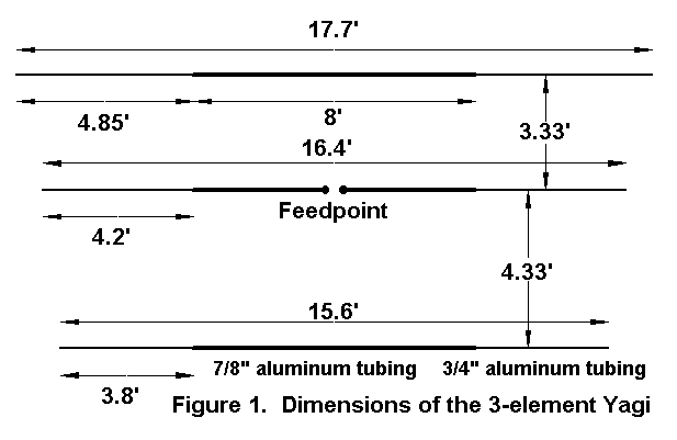
Figure 1 shows the dimensions of the antenna. The inner 8' of tubing for each element is 7/8" diameter, with the remaining length consisting of 3/4" diameter stock. Three 8' lengths of 7/8" tubing and six 6' lengths of 3/4" tubing are all you need. You can fasten the tubing lengths with sheet metal screws, stainless steel hose clamps (with stainless steel screws), or "pop" rivets. Do not waste weight by using too much overlap in the tubing sections: 2-4" will do nicely. The reflector and the director are continuous elements, but the driven element is split in the middle for the matching system. I use small well- varnished (spar varnish) plywood plates to hold the elements to the boom--you can see the details in almost any of the other Yagi columns.
My favorite 2-element boom--Schedule 40 PVC--gets a bit heavy by the time the boom reaches 8' long. So you might want to use 1.25" or larger diameter aluminum. A light-weight section of TV masting (the kind so light that I would never recommend that it be used as a mast) would also work if you are sure that it will stand the weather and not rust out in the first season.
The key to the antenna is the matching system. My favorite for small antennas is the beta match, but a gamma or Tee match would do as well. The driven element length is set for a beta match, with a resistance of about 25 ohms and a reactance between 20 and 25 ohms. The reactance is the virtual series reactance needed by an L-circuit to transform the 50-Ohm coax cable impedance down to the 25-Ohm resistive antenna impedance.
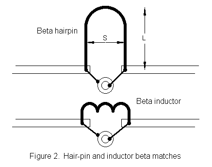
However, an L-circuit also needs an inductive reactance across the line, as shown in Figure 2. The inductive reactance can be a coil, as shown in the lower view. For 28.5 MHz and the 2:1 transformation needed here, the coil needs to be about 0.28 µH. A coil about 0.5" in diameter and wound with #12 copper house wire will have 6 turns spread over about 3/4" of length with half-inch leads to meet this need.

The inductive reactance can also be a shorted transmission line stub or "hairpin." The hairpin can have many dimensions, depending on the wire thickness and the spacing. With a spacing (S) of 2" between wires, a hairpin of 1/8" wire will be about 7.7" long (L), while a similarly spaced hairpin of #12 wire will be about 6.8" long.
In real life, not everything is exact, and the hairpin or coil may need adjusting to achieve a 1:1 SWR at the target frequency (28.5 MHz in this case). You can adjust the length and/or spacing of the hairpin. Likewise, you can squeeze or spread the coil turns. If neither trick works, adjust the length of the driven element and try again.
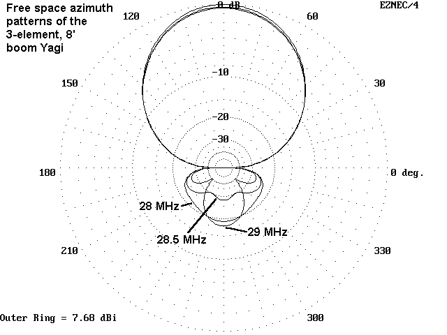
How well does the antenna work? Across the first MHz of 10 meters, the gain ranges from about 7.3 dBi to 7.7 dBi (free space gain. In comparative terms, this is about halfway between the gain of the wide-band 50-Ohm beam and a highly optimized 3-element beam with a boom length of about 12' or so. The gain is high enough to compete favorably with most 3-element tri-banders on 10 meters. Figure 3 shows the pattern at 3 point across the band.

The front-to-back ratio is about 18 dB at the band edges, but for most of the span between it is well over 20 dB, peaking above 27 dB near center band. Not too bad for an 8' boom.
The entire beam will weight between 8 and 10 pounds,
including the boom, depending on the materials used. An old
TV rotator will turn it, and a guyed push-up mast or roof-top
"tower" will put it at a good height. Remember that the fairly
high front-to-back ratio is not only a QRM killer, but also a
closed back door. In a local net or similar operations, you may
also want to have a simple vertical or dipole around to tell when
there are signals off the rear waiting for you to turn the beam in
their direction.
Updated 10-2-98. © L. B. Cebik, W4RNL. Data may be used for personal purposes, but may not be reproduced for publication in print or any other medium without permission of the author.