 No. 24: Three Ways to Skin a Quad Loop

A single quad loop makes a compact and effective bi-directional array for 10 meters. It has somewhat more gain than a dipole, and most users note that it is quiet, that is, not as susceptible to local noise as an open-ended dipole. With some sort of supporting system, the loop is a good choice for many ham back yards.
A quad loop does its work with the antenna in the vertical plane, like a giant fly swatter. Maximum radiation is off the two broad surfaces and is minimum off the edges.
Now comes the hard part: deciding what kind of loop to use. There are at least three versions, each with advantages and disadvantages. Let's look at them in order of complexity.
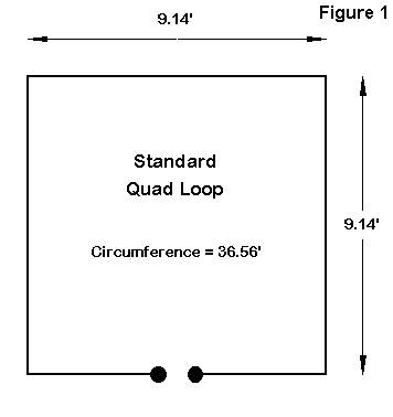
The feedpoint impedance is about 125 Ohms at the 28.5 MHz design resonance frequency. A quarter wavelength section of 75-Ohm coax (about 5.7' of standard RG-59 with a velocity factor of 0.66) will provide a very low-loss match for the 50-Ohm coax to the shack and provide less than 2:1 SWR over all of the first MHz of 10 meters, plus a little. With this set-up, the antenna has the broadest operating bandwidth of all of the loops we shall examine.
The old standard way of making a quad loop is to use criss- cross spreaders of bamboo, fiberglass, or--more recently--PVC. However, there are no rules that forbid you from stretching the quad loop from its corners to trees or other vertical supports. You can also use tubular horizontal members and wires vertical sides, although you may have to adjust the dimensions--most likely to enlarge them a bit.
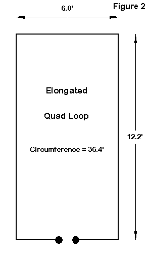
Fig. 2 shows the dimensions of a #12 AWG copper wire loop meeting these goals. The feedpoint impedance is almost exactly 50 Ohms at 28.5 MHz. However, the 2:1 SWR operating bandwidth is only about 800 kHz, somewhat narrower than the standard loop with a matching section attached.
The gain of the loop with the bottom wire at about 35' is 8.9 dBi (4.2 dBi in free space), and the taller assembly lowers the take- off angle to 17 degrees. Both the gain and the lower angle of maximum radiation contribute a little extra to our DXing efforts.
Most likely, you would want to build a fixed version of this kind of loop by supporting the wire from its corners by ropes running to adjacent supports. As an alternative, you can build a rotatable version by using tubular horizontals and wire vertical sides (again, with dimensional adjustments that owe to the fat horizontal elements) attached to (but insulated from) a center mast. With a height about 3' taller than the normal quad loop, support requires a bit more work than the standard loop. Yet, if the top of this loop and the top of the standard loop are level with each other, this elongated loop loses some of its advantages in gain and lowered take-off angle.
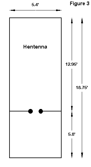
The gain of this antenna, if the bottom wire is at the same level as the other two loops (1 wavelength or 35'), is about 9.8 dB (5.0 dBi in free space), with a take-off angle of 15 degrees, making it a good DX antenna among loops. However, its performance depends very much on the added height of the upper wire, which is nearly 19' from the bottom. The antenna is 60% as wide but more than twice as tall as the standard square loop. If we lower the top wire to parallel it with the top wires of the other two loop designs, the hentenna turns out to be only a little better than they are.
The operating 2:1 SWR bandwidth is the narrowest of the three loops, about 600 kHz or a little over half of the first MHz on 10 meters with the design frequency of 28.5 MHz used here. Like the other loops, construction can be all wire, with the corners attached by thin (UV-resistant) rope to supports. Or, you can once more use larger diameter upper and lower horizontal members with wires sides and a wire feedpoint element for a rotatable antenna.
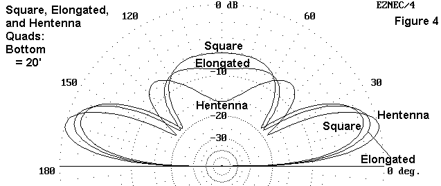
Fig. 4 compares the antennas using a common bottom horizontal wire height of 20'. This arrangement places the elongated loop top wire above that of the square loop, and the hentenna top wire above both the others. The advantage in gain and lowered angle of radiation for the larger kloops is clear.
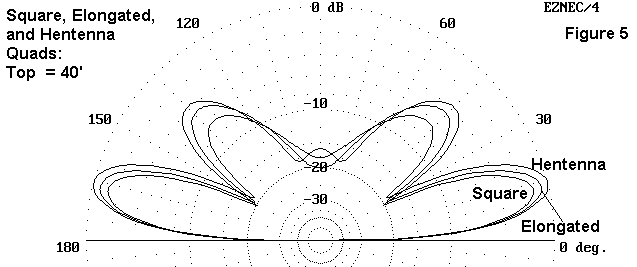
Fig. 5 reverses the procedure and places the top wires of all 3 antennas at 40' up. For many installations, top height is more absolute than bottom height. In this configuration, all three antennas have comparable TO angles, with only small gain advantages as the loops grow larger.
Whichever loop you choose, assuming that a loop fits your operating needs, give your best ingenuity to construction. If at all possible, figure out how to make the antenna free standing so that you can rotate it by hand (if not by a TV rotator). You will need to turn at most less than a half turn, since the antenna is bidirectional. All of the loops have very deep side nulls on a plane with the wires, and just these nulls alone can get rid of more than half the QRM that might get in the way of your QSOs.
Loops are also handy in contests, where you really do want to hear what is happening in most directions. You never know in advance from where your next contact will come. If you build the loop to be collapsible, you can set it up for Field Day and other hilltopping exercises.
The basic quad loop is a versatile antenna that lends itself to many construction techniques. If you want a little more performance than a dipole can give and you think it is fun to have a fly swatter waving in the breeze above your QTH, then one of these three designs may be the next antenna to build.
Updated 7-20-99. © L. B. Cebik, W4RNL. Data may be used for personal purposes, but may not be reproduced for publication in print or any other medium without permission of the author.