
In fact, there is. Moreover, the B-antenna has some interesting features. While I doubt many hams would build one as it is presented here, some aspects of the scheme might be useful in future antenna designs for special circumstances.
Imagine yourself limited to either 10' vertically or 10' horizontally as your maximum length for a 10-meter antenna. This is less than 0.3 wavelengths. Most folks would set aside all thoughts of a dipole, either vertical or horizontal. The 1/4 wavelength vertical seems to be the antenna that best fits the space. If a dipole creeps into the picture at all, the assembly would likely involve lossy inductive loads.

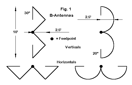
Enter the "B" as a possible antenna of choice. Figure 1 shows both a straight-line B and a rounded B. (Of course, from the other side, the straight-line B looks like a sigma, but it is too early in the article to destroy an illusion.) The figure also shows both versions in vertical and in horizontal orientations. The dimensions are the same for both.
The key to the antenna is the fold-back portion. The fold-back is longer on the straight-line version because the total length of the zig-zag section is less than the length in the double hump of the rounded version. In any event, fold-back lengths are approximate, based on models that used 0.25" diameter aluminum.
If you use thinner material, the length could be shorter. "Shorter" cuts against the grain of conventional dipole thinking, where thinner means longer. However, the fold-back creates a more closed geometry in which-- like quads--thinner means shorter. Actually, the antenna is quite stable for a good range of diameters, so the end lengths will mostly be a function of the particular construction method and precision level chosen. Shortening or lengthening the fold-back is the easiest route to resonance.
Most straight-line dipoles that employ a fold-back tend to show higher losses than with the B-antenna. The fold-back is so close to the main wire, that considerable cancellation occurs, especially as the end section reaches further into the higher current portions of the dipole wire. With the B-antenna, the fold-back is further from the main wire and the loss of gain is minimal.
In effect, the fold-back is a non-symmetrical capacity hat. All forms of non-symmetrical end loading tend to decrease gain and feedpoint impedance a bit more than symmetrical hats. However, the greater simplicity of fold- backs and other non-symmetrical end extensions may offset those slight deficiencies, depending on the builder's circumstances.

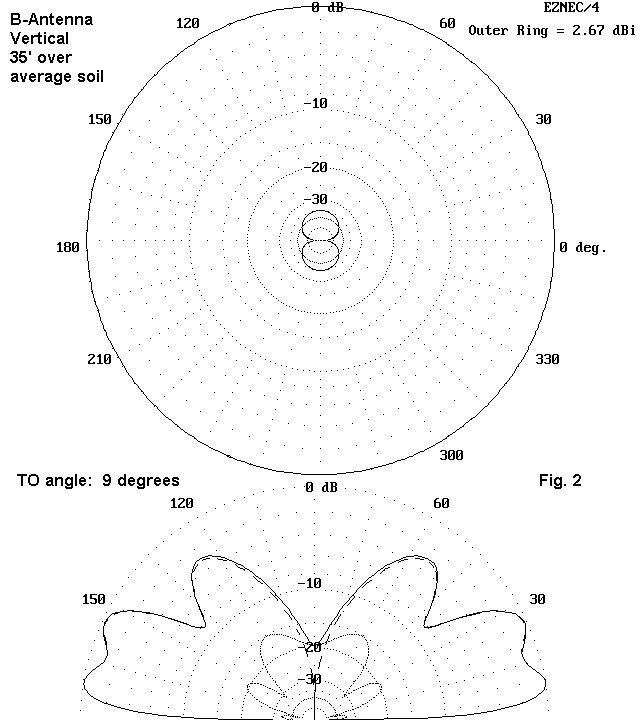
Figure 2 shows modeled azimuth (at take-off angle) and elevation patterns for the vertical version of the antenna, with the feedpoint 40' above average soil. The azimuth pattern proves that the B-bulges do not bother the circularity of the azimuth pattern. The gain is quite similar to the gain of a full-size vertical dipole with the feedpoint at the same height.

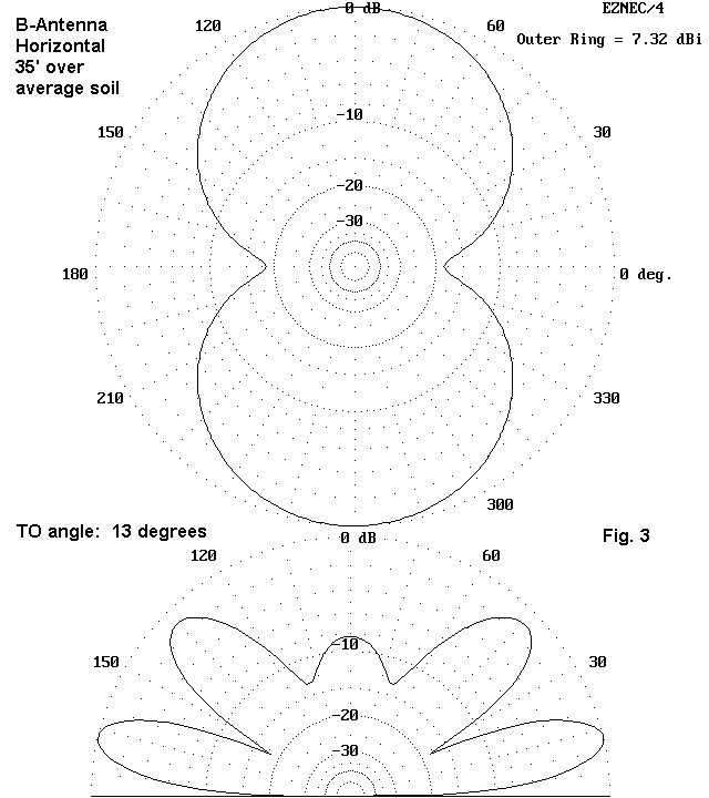
Figure 3 shows modeled azimuth (at take-off angle) and elevation pattern for the horizontal version of the antenna, with the feedpoint 35' over average soil. The maximum gain is only about 0.3 dB less than a full size dipole at the same height, and the elevation angle of maximum radiation is the same. The side rejection equals or surpasses that of a full-size dipole at the same height. As a rotatable dipole, the B would do well at reducing QRM from the sides.

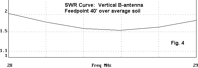
Figure 4 is a modeled 50-Ohm SWR curve for the vertical version of the antenna, when set between 35 and 45 feet above ground. This range places the feedpoint at the 40' level. The source reactance from band-edge to band-edge changes from -20 to +19 Ohms, which is quite modest for the band spread involved. The resistive component of the source impedance changes very little at all.
Consider a vertical version of the rounded B. You can use aluminum rod to form each bulge. An 8' piece is perfect for each bulge. 3/16" or 1/4" diameter material would be ideal. If you have some tubing (3/8" diameter or less), it would also work. Make a half circle from scrap wood. Bend the rod around the form. Setting a bend requires an overbend so that the material returns to the desired size. Leave the piece with just a little outward flare.
Tubing should be filled with sand--or kitty litter, in a pinch. Bend slowly, using nails to pin the bend to the form every few inches.
To mount the B-bulges, use a 10' piece of 1" nominal Schedule 40 PVC. Drill holes at each end to pass the rod all the way through the tube. Drill a pair of holes with a small space between them for the rods that almost come together at the center. Since the antenna is a dipole, we shall feed it at this center junction. The outward pressure of the bent pieces will help rigidify the PVC.
Use small stainless steel machine screws run through holes in the bent rods or tubes to act as stops, preventing the bent pieces from moving either way through the holes, once they are in place. Alternatively, you can drill smaller holes in the rod or tubing on each side of the PVC and make a c- shaped wire clip to go around the PVC, through the holes, and then in a right-angle bend to keep it in place. Wire that is run down from the outer ends of the bent pieces and along the PVC--taped in place--will work fine for the fold-back lengths.
For a horizontal version of the antenna, you can simply rotate the PVC 90 degrees. If this assembly is too heavy, you can always string a pair of UV resistant ropes between two end supports. The ropes should be vertically spaced by 30 inches. Now, zig-zag the wire between ropes, running the fold-back along one of them. Models suggest almost no difference between pointing the peaks up or pointing them down.
A 30-Ohm feedpoint impedance is a borderline condition at 10 meters. If it seems too low to you for direct coax connection, you can shorten the antenna to create a modest capacitive reactance. Then, install a hairpin or beta coil across the feedpoint. Any ARRL Antenna Book has details on the beta match. HAMCALC, from VE3ERP, has a handy beta-match hairpin calculator. The feedpoint can also be used with a section of 37.5-Ohm coax as a matching section. (Paralleled 75-Ohm coax will yield this line.) Since the feed impedance is a bit high for a perfect match with 1/4 wavelength of the matching section, you may wish to experiment with shorter sections, in accord with my recent notes in AntenneX on when a quarter wavelength is not a quarter wavelength.
For those who enjoy experimenting with antennas--either by building or by modeling--The B-antenna is a good test bed to use for looking at the effects of folding back the ends of an antenna element to achieve resonance. The goal is to find compact ways of doing this with the least loss and least reduction in feedpoint impedance. Maintaining a wide operating bandwidth and a stable feedpoint impedance in which the reactance does not change very rapidly are also desirable goals for the project. The B-antenna does quite well on most of these scores, however impractical the geometry might prove to be.
What started out as curiosity aroused by a joke turned out to be an instructive exercise. Not every antenna exercise has to result in the world's best radiator in order to be productive and informative. In fact, I have learned as much from examining bad antenna ideas as from analyzing good ones. The B-antenna is not bad; instead, the design has a limited utility and is aimed at that special set of circumstances calling for it.
Now if I use an A-frame to support my B-antenna with C-clamps, D-rings, and E-clips, I am well down the road to alphabet insanity.
Updated 2-5-99. © L. B. Cebik, W4RNL. This item first appeared in AntenneX, Sep., 1998. Data may be used for personal purposes, but may not be reproduced for publication in print or any other medium without permission of the author.