 Some Notes on Antenna Bandwidth
For most of us, the antenna's bandwidth is the number of Hz for which the antenna will exhibit a less than 2:1 SWR. We usually measure bandwidth at the transmitter output, and hence put a large pile of variables on top of the basic idea of SWR bandwidth. So let's begin again and see how the concept actually works.
An antenna--for example, a resonant half-wavelength dipole operated on its fundamental frequency--has a natural feedpoint impedance. For a lossless wire dipole in free space, that figure is just about 72 ohms. In fact, NEC-2 models of just such an antenna using wire diameters from #30 to over 2.5" show less than 1 ohm variation in the 72-ohm feedpoint impedance.
Relative to that impedance, a 2:1 SWR will occur as the feedpoint impedance (off resonance, a complex of resistance and reactance) reaches about 144 ohms at points higher or lower than resonance. The number of Hz (of kHZ or MHz) between those frequencies is the 2:1 SWR bandwidth of the antenna. The bandwidth will vary with the diameter of the antenna element in a regular but nonlinear manner.
2:1 SWR bandwidth is approximately (but again, nonlinearly) proportional to frequency. For a given wire size, a resonant dipole at 28 MHz will have (about) twice the bandwidth of a resonant dipole at 14 MHz.
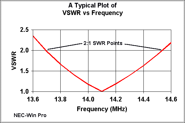
Below is a typical frequency vs. bandwidth plot for a free space lossless thin-wire dipole, plotted against a 72-ohm resonant feedpoint impedance.
To help you gain a reasonable expectation of the 2:1 SWR bandwidth of resonant half-wavelength dipoles, I am attaching a small BASIC utility program that will produce bandwidth tables for any HF frequency for wires from #30 (0.01" diameter) to 2.5" diameter. It is roughly calibrated to NEC-2 models for lossless wire resonant dipoles in free space and to 72 ohms. The algorithms are generally accurate to about 5%, with some matrix-center variations reaching about 10%. The figures are roughly applicable also to resonant quarter-wavelength vertical antennas.
Table 1 sumarizes a few data points for thin, medium, and thick antenna
elements on 80, 40, 20, and 10 meters. The increase of bandwidth with
frequency for a given wire size is evident. Notice also that it takes nearly
a 100:1 wire size increse to double the bandwidth of the antenna on any given
frequency.
| Table 1: Selected 2:1 SWR Bandwidths in MHz for Wire Antennas | ||||
|---|---|---|---|---|
| Frequency | 3.5 MHz | 7 MHz | 14 MHz | 28 MHz |
| #28 AWG (0.013") | 0.17 | 0.35 | 0.73 | 1.63 |
| #12 AWG (0.081") | 0.19 | 0.40 | 0.86 | 1.91 |
| #4 AWG (0.204") | 0.22 | 0.46 | 0.98 | 2.18 |
| (1") | 0.30 | 0.63 | 1.35 | 3.06 |
The degree of error in the program is of no concern, since real antennas and antenna systems will introduce larger variations that no table can account for in advance. Hence, the program is only for setting some reasonable expectations, not for predicting bandwidth wit precision. The bandwidth you actually measure will vary with the following variables:
1. Antenna type: Low impedance antenna types will generally (but not always) have wider bandwidths than high impedance antennas.
2. Antenna material: Copper and aluminum have losses that affect antenna bandwidth, especially with small diameter wires (less than #20).
3. Antenna environment: Placing an antenna some height above ground less than about 2 wavelengths will alter both the natural feedpoint impedance and the bandwidth at that impedance. Ground clutter in the near field of the antenna will affect both in ways that are for practical purposes unpredictable.
4. Feedline mismatch: Feeding a 72-ohm antenna with our common 50-ohm coax starts us out at 1.4:1 SWR, hence decreasing the 2:1 SWR bandwidth. As a rule of thumb, the reduction is approximately the same as the ratio of feedpoint impedance to the feedline impedance--or the inverse of the lowest SWR obtainable. Hence, we should expect about 70% of the program's estimated bandwidth when feeding the dipole with 50-ohm coax. (This fact explains why some claim a slightly wider band width for inverted Vee configurations: being closer to 50 ohm natural feedpoint impedance, Vees introduce less bandwidth narrowing due to the slight mismatch).
5. Feedline losses: Even well-matched transmitter-feedline-antenna systems introduce some losses in the feedline. The effect of these losses is to reduce the SWR at the transmitter end of the line, thus giving a wider 2:1 SWR bandwidth. This wider bandwidth is usable, so long as we understand and evaluate the acceptability of the power losses involved.
6. Antenna shortening and loading: Although antenna loading for the sake of shortening reduces the feedpoint impedance, it introduces components that raise antenna Q and narrow the bandwidth. As a rule of thumb, bandwidth is reduced by the percentage of shortening of the antenna. For example, a 33' vertical on 80 meters is about half size, and its bandwidth is about 70 kHz for most common loading schemes--just about half the bandwidth of a full size quarter-wave vertical.
Understanding these bandwidth-altering factors along with the basic output of the program can give us reasonable expectations for antenna bandwidth for the various bands. If our antenna system is more than about 20% off the mark, then we begin to search for possible problems.
Remember that these notes do not apply to antennas fed with parallel feedline and an ATU: those we always tune for 1:1 SWR and maximum power output to the line and antenna.
Finally, if you do not like typing BASIC programs or converting them to
C, a version of the program appears in VE3ERP's HAMCALC collection,
available in the Lehigh.edu archives or directly from Murph: VE3ERP, 77 McKenzie Street, Orillia, Ontario L3V 6A6, Canada.
10 ' BW.BAS
20 CLS:SCREEN 0: COLOR 2,,4:CLS
30 ER$=STRING$(70,32):BW$="###.###":WIRE$="#.###":S$=STRING$(10,32):T$=STRING$(6,
32)
40 ' Estimates 2:1 SWR bandwidth of halfwavelength dipoles for a range of
     common wire and tubing sizes.  Algorithm is based on NEC models of
     lossless wire dipoles in free space and is based on a feedpoint
50 ' impedance of 72 ohms.  Program does not account for material losses,
     feedline losses, mismatches, or the antenna environment.  Accuracy
     averages 5%.
60 PRINT "   Estimated 2:1 SWR bandwidth of half-wavelength dipoles at any HF
frequency"
70 LOCATE 2,25:PRINT "by L. B. Cebik, W4RNL"
80 LOCATE 3,15:INPUT "Enter any frequency from 3 - 30 MHz:   ",F
90 IF F>30 OR F<3 THEN LOCATE 3,5:PRINT ER$:GOTO 80
100 PRINT "Wire size","Wire dia.","Bandwidth";S$;"Wire
dia.";T$;"Bandwidth"::PRINT "  AWG  ","inches","   MHz  ";S$;"  inches",T$;"
MHz   "
110 FOR J=30 TO 2 STEP -2
120 AWG$=MKS$(J):N=J:AWG=J
130 K#=(.46/.005)^(1/39):WIRE=.46/K#^(N+3):DIA=WIRE
140 DIA2=DIA-((.4343*LOG(30/F))*(DIA/(2*(2.56/DIA))))
150 BWBASE=(.0469+(((F/3)-1)*(.0116/9)))*F
160 BW=((SQR(DIA2))+.9)*BWBASE
170 PRINT AWG,:PRINT USING WIRE$;WIRE,:PRINT" ",:PRINT USING BW$;BW
180 NEXT
190 FOR J=.375 TO 2.5 STEP .125
200 DIA=J
210 DIA2=DIA-((.4343*LOG(30/F))*(DIA/(2*(2.56/DIA))))
220 BWBASE=(.0469+(((F/3)-1)*(.0116/9)))*F
230 BW=((SQR(DIA2))+.9)*BWBASE
240 K=(J*8)+3:LOCATE K,50
250 PRINT USING WIRE$;J,:PRINT S$;:PRINT USING BW$;BW
260 NEXT
270 LOCATE 23,5:PRINT "Another (F)requency or (Q)uit"
280 A$=INKEY$
290 IF A$="f" OR A$="F" THEN 10 ELSE IF A$="q" OR A$="Q" THEN 300 ELSE 280
300 END
first printed in QRP Quarterly, January, 1997.