
 Some Pitfalls of Careless dBd-ing
In an earlier note on why I use dBi--mostly, written over 2 years ago, I distinguished several possible meaning for dBd, each of which was distinct.
dBd-I (Ideal): Since a free space lossless infinitely thin-wire dipole has a gain of 2.15 dBi (Isotropic), this interpretation of dBd simply subtracts 2.15 from the gain in dBi and presents a gain number. It has no application except in free space.
dBd-RM (Real Model): A dipole constructed of the same material as an antenna used for comparison and placed in a model at the same height over the same ground type may make a meaningful comparison. Many antennas with directional patterns (Yagis, for example) do not experience the same gain fluctuations as a dipole does at varying heights below 2 wl, so the comparison must be used with caution. By judicious selection of heights without revealing those numbers, one can make a given antenna look up to 0.5 dB better than itself.
dBd-RR (Real Range): A range test will use a relevantly similar dipole as a comparator for horizontally polarized gain antennas under carefully controlled test circumstances and procedures. Since the range test cannot use an isotropic radiator as the baseline comparator, translation of range tests into dBi is only dome with caution and often may be dispensed with altogether.
One of the difficulties of dealing with live claims of antenna (especially Yagi) gain given in dBd is that the sources rarely tell us which--if either--sensible meaning of dBd is being used. So we are left to our own devices in evaluating these claims. One major exception has been the independent comparative studies of N0AX and K7LXC (HF Tribander Performance, now in its 2nd expanded edition), which has used a thoroughly discussed and consistent methodology throughout. Even if one should disagree with any of the results obtained, one has at least a firm foundation for resolving outstanding issues.
1. Jim Lawson, W2PV, established in his classic, Yagi Antenna Design, that gain is a function of boom length and that for any given number of elements, there is a maximum gain length, after which gain tends to level of fall off. The maximum gain figures obtainable are accompanied by a quite narrow operational bandwidth over which they obtain and also by mediocre front-to-back (or front-to-rear) figures. More realistic gain expectations run at least 1 dB below maximums when accompanied by a satisfactorily broad operating bandwidth and a reasonable front-to-back ratio--usually expressed in terms of a 20 dB standard.
However, if we are not careful, we can misuse Lawson's work by putting into out minds a single figure for a given boom length and forgetting the bandwidth aspect of the situation.
2. Programs like YA (the K6STI variant of his full featured YO Yagi Optimizing program) can develop a good sense of what is sensible with Yagi design, using the N6BV optimized designs plus some others of local origin. The key is to use the graphical outputs to supplement number sets in order to understand the performance of Yagis across a desired bandwidth.
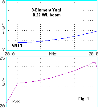
Fig. 1 shows the gain and front-to-rear performance of a 3-element Yagi on a 0.22 wl boom (about 8') for the 10-meter band. Note that the gain climbs steadily across the band from below 7.2 dBi to nearly 7.5 dBi. I this design, the front-to-rear ratio creates a plateau, with a rapid fall-off at either end of the band covered.
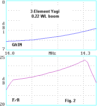
In Fig. 2, we have essentially a scaled version of the same antenna (0.22 wl boom, about 16') for the 20-meter band. The gain progression yields quite similar numbers, and the front-to-rear plateau is simply displaced in the band slightly, relative to the 10-meter curve.
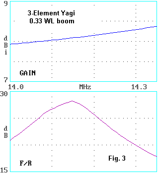
If we lengthen the boom to about 0.33 wl (about 24'), we can obtain additional gain, as shown in Fig. 3. As with most 3-element deigns, the gain increases across the band from about 7.95 dBi to 8.4 dBi. In this design, the front-to-rear ratio peaks at a very high value, but at the upper end of the band it drops to about 18 dB.
If we compare antenna gains in terms of dBd-I--since these are free space models--then the 0.22 wl beam provides a gain range of 5.0 to 5.3 dBd-I, while the longer boom model runs from 5.8 to 6.2 dBd-I. Note that these numbers apply to aluminum elements that are full length. On 20 meters the maximum reflector length is about 34.5', while on 10, the same element is over 17' long.
In general, these are quite good numbers considering the composite specification requirements for gain, front-to-rear ratio, and operating bandwidth. (It should be clear that I am ignoring matching considerations in this discussion.)
Triband Yagis of boom lengths similar to those used in the examples can approach the monoband figures, but only through the use of added elements--which may take a number of forms. Out-of-band elements may contribute to gain on a given band if their positions provide some "forward stagger" effect. Negative effects of an out-of-band element can be (sometimes) overcome by the careful placement of a compensating in-band element. In evaluating tribanders, we should look at the boom length as a fraction of a wavelength for each band covered and develop gain standards accordingly.
Antenna                       A                   B
Gain:  10 m                   4.5 dBd             5.5 dBd
Gain:  15 m                   3.9 dBd             4.5 dBd
Gain:  20 m                   3.2 dBd             4.0 dBd
Boom length                   6.0'                9.8'
Longest element               16.8'               12.3'
Nowhere did I find any basis for these numbers, so my only recourse was to assess the claims against what I have learned about Yagis from modeling several hundred of them and building a number of the models in to functioning antennas.
Let's look at the higher claims for antenna B first. The 10-meter gain claim exceeds that obtained for the 0.22 wl boom monobander, even at its peak. However, the boomlength of B is 0.27 wl on 10 meters, so the gain claim has some initial plausibility. However, the elements are only 3/4s full size. Shortening elements of any dipole-based antenna array, such as the Yagi, will result in some slight gain reduction per element, which is cumulative. These numbers do not specify how the elements are electrically lengthened to full size--or even if the entire element is functional on 10 meters.
On 15 and 20 meters, the elements diminish to a maximum of one-half and one-third full size. The boom length reduces to 0.22 wl and 0.14 wl for 15 and 20, respectively. The gain of a 2-element Yagi (driver and reflector) using full size elements will be about 6.2 dBi or 4.0 dBd-I in free space for a spacing of 0.12 to 0.15 wl. That gain will vary across the band, and since it lacks a director, the gain will fall with increasing frequency. Yet antenna B, with element only 1/3 full size and no specification of the means of electrical lengthening claims the same gain.
The claims of antenna A are more modest. On 10 meters, the claimed gain is about the peak gain of a decent 2-element monoband beam using the same boom length--6 feet. This antenna uses elements that are full length on 10 meters, but once more does not in these numbers specify how much of the element is active on each band.
On 15 and 20, the elements shrink to 3/4 and 1/2 full size, but once more, without specification of electrical lengthening methods or the amount active on each band. The boom length shrink to 0.135 wl and 0.085 wl on 15 and 10, respectively.
Of course, if dBd does not mean dBd-I, then this entire exercise is meaningless. However, so too are the gain numbers claimed, since they have no reference. Even should someone to claim, "This is what I measured on the range," (that is, used dBd-RR), we would have to have a complete description of the test methodology and the dipole used as a comparator before we could begin to assess the numbers.
If the numbers refer to dBd-RM, then--of course--one wants to see the models used and to assess them for oneself. That would require the revelation of far more technical detail than is usually made available to potential buyers. We may note again in these numbers the absence of data regarding the active length of each element on each band and the method of electrically lengthening elements to full size.
Hence, for the case study used here, one must regretfully conclude that in the absence of much more extensive data, the numbers are meaningless. Of course, one set of meaningless numbers compared to another set of meaningless numbers yields a meaningless comparison. From the claimed figures we learn nothing about the respective antennas--except the length of their longest elements and their boom lengths. Unspecified used of dBd for gain claims too often leads to just this result.
However, even had the numbers been given in dBi, one still would have had to know a great deal more before those numbers would have been in any way informative. Spot numbers--even based on published models or tests--are potentially misleading. Curves across a desired operational bandwidth are far more informative.
Updated 6-3-99. © L. B. Cebik, W4RNL. Data may be used for personal purposes, but may not be reproduced for publication in print or any other medium without permission of the author.