
 Phased Yagis, EDZ Beams, and
Landsdorfer-Sacher Yagis
Phased Yagis, EDZ Beams, and
Landsdorfer-Sacher YagisAlthough there are some hints on the subject in other notes, it seemed useful to me to review for my own edification the relationship between Phased Yagis and Extended Double-Zepp (EDZ) beams. That review might position us to understand another type of antenna, the Landsdorfer-Sacher Yagi.
Ever since the amateur community was introduced to EDZ beams in a QST article by Hugo Romander, W2NB, in June, 1938 ("The Extended Double Zepp Antenna"), perhaps too many hams have thought of the EDZ as a special type of 1.25 wl antenna. In fact, it is simply a way of doing some things that we can do with ordinary half-wavelength antenna elements. So let's begin with antennas using half-wavelength elements. A 2-meter 3-element Yagi seems straight-forward enough for our purposes. We shall set 145 MHz as our design frequency, hoping for at least 2 MHz of coverage on the band.

As a reference, here is the EZNEC model description of the antenna pair:
2 Yagis, 3-el, 3/16" el                      Frequency = 145  MHz.

Wire Loss: Aluminum -- Resistivity = 4E-08 ohm-m, Rel. Perm. = 1

              --------------- WIRES ---------------
Wire Conn.--- End 1 (x,y,z : in)  Conn.--- End 2 (x,y,z : in)  Dia(in) Segs

1        -52.092,  0.000,  0.000       -11.868,  0.000,  0.000 1.88E-01  31
2        -51.142, 13.295,  0.000       -12.818, 13.295,  0.000 1.88E-01  31
3        -49.995, 27.413,  0.000       -13.965, 27.413,  0.000 1.88E-01  31
4         11.868,  0.000,  0.000        52.092,  0.000,  0.000 1.88E-01  31
5         12.818, 13.295,  0.000        51.142, 13.295,  0.000 1.88E-01  31
6         13.965, 27.413,  0.000        49.995, 27.413,  0.000 1.88E-01  31
7         -0.100,  0.000,-20.000         0.100,  0.000,-20.000    # 14    1

              -------------- SOURCES --------------
Source    Wire      Wire #/Pct From End 1    Ampl.(V, A)  Phase(Deg.)  Type
          Seg.     Actual      (Specified)
1           1     7 / 50.00   (  7 / 50.00)      1.000       0.000       I

                -------- TRANSMISSION LINES ---------
Line  Wire #/% From End 1   Wire #/% From End 1   Length     Z0   Vel Rev/
      Actual  (Specified)   Actual  (Specified)              Ohms Fact Norm
1     2/50.0  (  2/50.0)    7/50.0  (  7/50.0)   61.050 in    50.0  1.00  N
2     5/50.0  (  5/50.0)    7/50.0  (  7/50.0)   61.050 in    50.0  1.00  N

Ground type is Free Space
Note that the array of Yagis at its widest point is about 104.2" wide or a little over 1.25 wl at the design frequency (where a wl is about 81.4"). Wire 7 in the model is the junction wire for the two transmission lines. Since the two feedpoints are more than 1/2 wl apart, the feedlines are each 3/4 wl long. Phasing line losses and velocity factor are not accounted for in the model. Each Yagi has a natural feedpoint impedance of about 25 Ohms at resonance, so the 50-Ohm lines transform the impedance to 100 Ohms, for a parallel combination that matches a main 50-Ohm feedline.
The antenna material is aluminum and the element diameter is 3/16", and both figures will remain constant in this exercise. Likewise, all modeling will be done in free space.
The modeled performance of the antenna pair is recorded in the following table:
Freq.     Gain dBi       F-B dB         R +/- jX       50-Ohm
MHz                                       Ohms          VSWR
144       10.9           24.3           45 + j14       1.35
145       11.0           23.9           51 - j 1       1.04
146       11.1           20.0           46 - j18       1.47
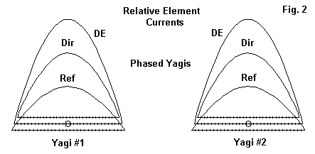
The SWR curve indicates that we might have moved the design frequency up by a half MHz and had a 2:1 SWR from 144 to 147 MHz. However, for our purposes, it is not the precise numbers that matter so much as the relative currents on the antenna elements. Fig. 2 shows the relative values of current for the reflector, director and driver for each antenna. Not surprisingly, the two antennas show the same values.
The free space azimuth pattern for the array appears in Fig. 3. Note the "ears" or "wings" in both the forward and rear quadrants. These minor lobes are typical of side-by-side arrays of this type. The wider the spacing between elements (to a point), the higher the overall gain, but as well, the stronger the side lobes.
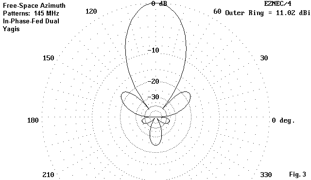
Achieving the full gain of the antenna relative to a remote power source depends on the losses accrued in the phasing lines (as well as the main feedline). Standard coax cables become noticeably lossy at 2 meters, and low-loss types or even hardlines are recommended for this application. The phased pair of Yagis is our baseline against which we shall compare the other antennas in this exercise.

We can focus on the parasitic elements and see the antenna as two Yagis with a common EDZ driven element. Or, we can focus on the driver and see the antenna as an EDZ beam with separate sets of parasitic elements. The particular model we shall examine is described in the following table:
2 Yagis w/ EDZ driver                         Frequency = 145  MHz.

Wire Loss: Aluminum -- Resistivity = 4E-08 ohm-m, Rel. Perm. = 1

              --------------- WIRES ---------------
Wire Conn.--- End 1 (x,y,z : in)  Conn.--- End 2 (x,y,z : in)  Dia(in) Segs

1        -49.200,  0.000,  0.000        49.200,  0.000,  0.000 1.88E-01  31
2        -49.200,-12.000,  0.000        -9.700,-12.000,  0.000 1.88E-01  13
3          9.700,-12.000,  0.000        49.200,-12.000,  0.000 1.88E-01  13
4        -49.200, 12.000,  0.000       -12.500, 12.000,  0.000 1.88E-01  13
5         12.500, 12.000,  0.000        49.200, 12.000,  0.000 1.88E-01  13

             -------------- SOURCES --------------
Source    Wire     Wire #/Pct From End 1    Ampl.(V, A)  Phase(Deg.)  Type
          Seg.     Actual      (Specified)
1          16     1 / 50.00   (  1 / 50.00)      1.000       0.000       I

              --------------- LOADS ---------------
Load      Wire      Wire #/Pct From End 1      R (Ohms)       X(Ohms)
          Seg.     Actual      (Specified)
1          16     1 / 50.00   (  1 / 50.00)       2.000       608.000

Ground type is Free Space
The overall width of the antenna is about 98.4" wide, with all the elements meeting this boundary. The constant outside dimension means that the reflector inside ends are closer together than the director inside ends. (Note also that for modeling convenience, the driver is listed as wire 1.) Since the EDZ driver is very capacitively reactive, an inductive load of 608 Ohms is required at the feedpoint to produce resonance. However, this resonant value is very close to 50 Ohms. The 2-Ohm resistive component of the load is to set the Q at about 300.
The following table of values is not strictly correct, since an impedance load was used. For precision, a series R-L load should have been put in place. However, the following values are indicative (with a very slight optimism at the band edges) of performance:
Freq.     Gain dBi       F-B dB         R +/- jX       50-Ohm
MHz                                       Ohms          VSWR
144       10.6           22.6           63 - j32       1.85
145       10.7           27.5           52 + j 0       1.05
146       10.8           19.9           43 + j33       2.04
This configuration produces a narrower operating bandwidth than the phase-fed independent Yagis. The gain figures of the two models should be considered as very comparable, since this model includes the load inductor losses, while the independent Yagis omit the phase line losses.
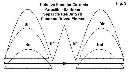
Fig. 5 shows perhaps the most significant difference between the arrays. The driven element has an additional smaller current peak at the wire center, but this peak contributes little or nothing to the overall gain of the system. The current patterns in the lines formed via bisecting each Yagi in the pair are virtually identical to those of the independent phase- fed Yagis.
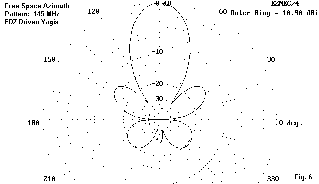
The azimuth pattern for this model, while differing a bit in rear detail, has all the same features as the pattern for the independent Yagis. The main forward and rearward lobes are accompanied by side lobes. In this case, the size of the rear side lobes is a function of setting the element dimensions to achieve a 50-Ohm feedpoint impedance. Smaller rear side-lobes are possible, but at a different feedpoint impedance.
In the end, this model with an EDZ driver is simply an extension of the initial model. The EDZ driver functions as 2 end-fed half-wavelength wires with a (roughly) 1/4 wl phasing section between them.
There is a second version of this same antenna that is worth noting in passing. It is possible to design the EDZ driver to be self-matching to a 50-Ohm feedline. The method involves adding to the inner ends of the Yagi drivers matching sections of some transmission line or other. The sections can be either coaxial lines or parallel lines. In the model in Fig. 19, the matching section uses parallel line with 1" spacing of the same 3/16" material used fror the elements. This particular antenna model is for the 220 MHz band. Note the gap in the unfed side of the matching section.
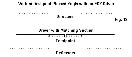
Dual Yagis with EDZ Driver                   Frequency = 223.5  MHz.

Wire Loss: Aluminum -- Resistivity = 4E-08 ohm-m, Rel. Perm. = 1

              --------------- WIRES ---------------
Wire Conn. --- End 1 (x,y,z : in)  Conn. --- End 2 (x,y,z : in)   Dia(in) Segs
1          -30.313,  0.000,  0.000  W2E1 -10.034,  0.000,  0.000 1.88E-01  21
2     W3E1 -10.034,  0.000,  0.000        -0.500,  0.000,  0.000 1.88E-01   9
3     W1E2 -10.034,  0.000,  0.000  W4E1 -10.034,  1.000,  0.000 1.88E-01   1
4     W3E2 -10.034,  1.000,  0.000  W5E1  10.034,  1.000,  0.000 1.88E-01  19
5     W4E2  10.034,  1.000,  0.000  W6E2  10.034,  0.000,  0.000 1.88E-01   1
6            0.500,  0.000,  0.000  W7E1  10.034,  0.000,  0.000 1.88E-01   9
7     W5E2  10.034,  0.000,  0.000        30.313,  0.000,  0.000 1.88E-01  21
8          -35.113,  8.450,  0.000        -9.295,  8.450,  0.000 1.88E-01  23
9            9.295,  8.450,  0.000        35.113,  8.450,  0.000 1.88E-01  23
10         -29.513,-13.203,  0.000        -8.978,-13.203,  0.000 1.88E-01  20
11           8.978,-13.203,  0.000        29.513,-13.203,  0.000 1.88E-01  20

              -------------- SOURCES --------------
Source    Wire      Wire #/Pct From End 1    Ampl.(V, A)  Phase(Deg.)  Type
          Seg.     Actual      (Specified)
1          10     4 / 50.00   (  4 / 50.00)      1.000       0.000       V

Ground type is Free Space
As shown in Fig. 20, the element currents are essentially the same as those for the loaded EDZ driver version of the antenna. Only the currents in the matching section show a variation.

Freq.     Gain dBi       F-B dB         R +/- jX       50-Ohm
MHz                                       Ohms          VSWR
222       10.1           14.2           45 - j16       1.42
223.5     10.1           15.1           44 + j 6       1.20
225       10.1           15.6           43 + j27       1.81
The mid-band free-space azimuth pattern appears in Fig. 21 for reference.
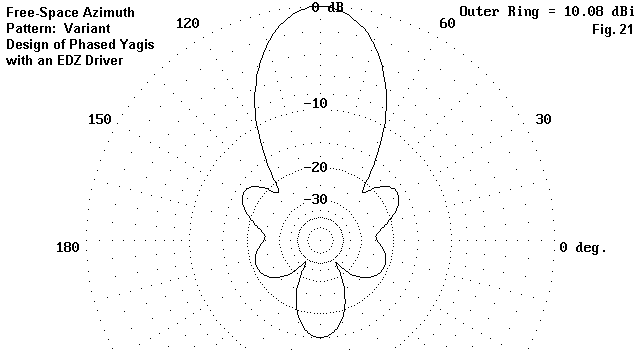
Although the technique of using a self-matching section in the driver provides for a mechanically simpler antenna than one employing loading inductors, the design is not without its own limitations. The parallel line spacing and the gap in the driver interact. So too do the overall driver length amd the required length of the matching line. As well, and unlike the loaded driver version of the antenna, careful left-right alignment of the parasitic elements is necessary to achieve maximum performance. Within these limitations, as an all-mechanical alternative to other all-mechanical designs below, the self-matching array has possibilities.
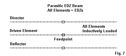
The result is a beam composed of 3 equal length EDZ wires. Of course, each wire will have to be loaded in accord with its function. The loading and the antenna dimensions appear in the table below:
3 el edz loaded 3/16" dia                   Frequency = 145  MHz.

Wire Loss: Aluminum -- Resistivity = 4E-08 ohm-m, Rel. Perm. = 1

              --------------- WIRES ---------------
Wire Conn.--- End 1 (x,y,z : in)  Conn.--- End 2 (x,y,z : in)  Dia(in) Segs
1        -49.200,-12.000,  0.000        49.200,-12.000,  0.000 1.88E-01  31
2        -49.200,  0.000,  0.000        49.200,  0.000,  0.000 1.88E-01  31
3        -49.200, 12.000,  0.000        49.200, 12.000,  0.000 1.88E-01  31

              -------------- SOURCES --------------
Source    Wire      Wire #/Pct From End 1    Ampl.(V, A)  Phase(Deg.)  Type
          Seg.     Actual      (Specified)
1          16     2 / 50.00   (  2 / 50.00)      1.000       0.000       I

              --------------- LOADS ---------------
Load      Wire      Wire #/Pct From End 1      R (Ohms)       X(Ohms)
          Seg.     Actual      (Specified)
1          16     1 / 50.00   (  1 / 50.00)       2.200       665.000
2          16     2 / 50.00   (  2 / 50.00)       1.900       565.000
3          16     3 / 50.00   (  3 / 50.00)       1.600       465.000

Ground type is Free Space
Like the preceding model, the overall antenna width is about 98.4" with 3/16" diameter aluminum elements. It is simply coincidental that the loading of each element works out to be about 100 Ohms different than the adjacent element--a function of balancing the antenna for peak performance at a near-50-Ohm feedpoint impedance. The modeled performance is captured in the following table:
Freq.     Gain dBi       F-B dB         R +/- jX       50-Ohm
MHz                                       Ohms          VSWR
144       10.5           17.5           56 - j26       1.65
145       10.6           39.5           51 + j 0       1.01
146       10.7           18.2           42 + j27       1.84
Relative to our initial pair of Yagis, the performance of this EDZ beam suffers about 0.25 dB as a result of element loading at a Q of 300 (compared to the previous model's loss of a little under 0.2 dB as a result of loading only the driver). Once more, an inexact loading system was used, but it does indicate a slightly wider operating bandwidth than the EDZ-driver-only model.
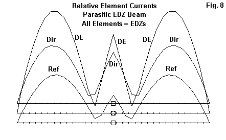
As we might expect, all three elements (in Fig. 8) show the center current peak inherent to an EDZ element. These peaks are not correctly phased to contribute to the overall array gain. The main work occurs in the 1/2 wl segments on either side of the feed and phasing area, and these curves show about the same relative strengths as in the corresponding earlier graphs.
The upshot is that an EDZ beam is actually two Yagis fed in-phase side-by- side with about 1/4 wl of spacing between them. The connecting wires are essentially phasing wires for the end feed of each element-end section.

The free-space azimuth pattern (Fig. 9) of the antenna model in question bears out this situation by showing all of the features of the other patterns. (The azimuth pattern reflects the potential of the antenna with zero-resistance loads.) What might otherwise be called the main rear lobe is, of course, almost non-existent, and only the rear side lobes show with prominence. It would not be stretching the point to note that all three of the beams we have examined so far are electrically of the same type, with only a few differences of implementation.
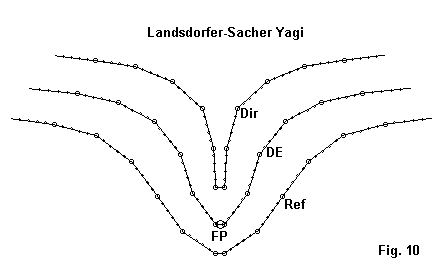
This 3-element array appears initially unusual because of its curved geometry--almost a line of pelicans fishing off the southern U.S. coastline. However, upon closer examination, we can fairly easily figure the function of various parts of the antenna. The model appears in the following table:
Landsdorfer-Sacher 2M Yagi                  Frequency = 145  MHz.

Wire Loss: Aluminum -- Resistivity = 4E-08 ohm-m, Rel. Perm. = 1

              --------------- WIRES ---------------
Wire Conn.--- End 1 (x,y,z : in)  Conn.--- End 2 (x,y,z : in)  Dia(in) Segs

1         16.417,-50.197,  0.000  W2E1  15.157,-39.252,  0.000 1.88E-01   5
2   W1E2  15.157,-39.252,  0.000  W3E1  12.323,-29.331,  0.000 1.88E-01   5
3   W2E2  12.323,-29.331,  0.000  W4E1   6.339,-20.906,  0.000 1.88E-01   5
4   W3E2   6.339,-20.906,  0.000  W5E1  -2.008,-14.843,  0.000 1.88E-01   5
5   W4E2  -2.008,-14.843,  0.000  W6E1 -10.354, -8.780,  0.000 1.88E-01   5
6   W5E2 -10.354, -8.780,  0.000  W7E1 -15.748, -0.984,  0.000 1.88E-01   5
7   W6E2 -15.748, -0.984,  0.000  W8E1 -15.748,  0.984,  0.000 1.88E-01   1
8   W7E2 -15.748,  0.984,  0.000  W9E1 -10.354,  8.780,  0.000 1.88E-01   5
9   W8E2 -10.354,  8.780,  0.000 W10E1  -2.008, 14.843,  0.000 1.88E-01   5
10  W9E2  -2.008, 14.843,  0.000 W11E1   6.339, 20.906,  0.000 1.88E-01   5
11 W10E2   6.339, 20.906,  0.000 W12E1  12.323, 29.331,  0.000 1.88E-01   5
12 W11E2  12.323, 29.331,  0.000 W13E1  15.157, 39.252,  0.000 1.88E-01   5
13 W12E2  15.157, 39.252,  0.000        16.417, 49.488,  0.000 1.88E-01   5
14        23.622,-45.079,  0.000 W15E1  22.362,-33.780,  0.000 1.88E-01   5
15 W14E2  22.362,-33.780,  0.000 W16E1  20.315,-24.173,  0.000 1.88E-01   5
16 W15E2  20.315,-24.173,  0.000 W17E1  15.709,-15.472,  0.000 1.88E-01   5
17 W16E2  15.709,-15.472,  0.000 W18E1   7.953, -9.409,  0.000 1.88E-01   5
18 W17E2   7.953, -9.409,  0.000 W19E1  -1.417, -6.457,  0.000 1.88E-01   5
19 W18E2  -1.417, -6.457,  0.000 W20E1  -8.858, -0.984,  0.000 1.88E-01   5
20 W19E2  -8.858, -0.984,  0.000 W21E1  -8.858,  0.984,  0.000 1.88E-01   1
21 W20E2  -8.858,  0.984,  0.000 W22E1  -1.417,  6.457,  0.000 1.88E-01   5
22 W21E2  -1.417,  6.457,  0.000 W23E1   7.953,  9.409,  0.000 1.88E-01   5
23 W22E2   7.953,  9.409,  0.000 W24E1  15.709, 15.472,  0.000 1.88E-01   5
24 W23E2  15.709, 15.472,  0.000 W25E1  20.315, 24.173,  0.000 1.88E-01   5
25 W24E2  20.315, 24.173,  0.000 W26E1  22.362, 33.780,  0.000 1.88E-01   5
26 W25E2  22.362, 33.780,  0.000        23.622, 45.079,  0.000 1.88E-01   5
27        31.575,-39.094,  0.000 W28E1  30.394,-29.567,  0.000 1.88E-01   5
28 W27E2  30.394,-29.567,  0.000 W29E1  28.898,-20.079,  0.000 1.88E-01   5
29 W28E2  28.898,-20.079,  0.000 W30E1  25.276,-11.181,  0.000 1.88E-01   5
30 W29E2  25.276,-11.181,  0.000 W31E1  18.740, -4.173,  0.000 1.88E-01   5
31 W30E2  18.740, -4.173,  0.000 W32E1   9.449, -1.654,  0.000 1.88E-01   5
32 W31E2   9.449, -1.654,  0.000 W33E1   0.000, -0.984,  0.000 1.88E-01   5
33 W32E2   0.000, -0.984,  0.000 W34E1   0.000,  0.984,  0.000 1.88E-01   1
34 W33E2   0.000,  0.984,  0.000 W35E1   9.449,  1.654,  0.000 1.88E-01   5
35 W34E2   9.449,  1.654,  0.000 W36E1  18.740,  4.173,  0.000 1.88E-01   5
36 W35E2  18.740,  4.173,  0.000 W37E1  25.276, 11.181,  0.000 1.88E-01   5
37 W36E2  25.276, 11.181,  0.000 W38E1  28.898, 20.079,  0.000 1.88E-01   5
38 W37E2  28.898, 20.079,  0.000 W39E1  30.394, 29.567,  0.000 1.88E-01   5
39 W38E2  30.394, 29.567,  0.000        31.575, 39.094,  0.000 1.88E-01   5

             -------------- SOURCES --------------
Source    Wire      Wire #/Pct From End 1    Ampl.(V, A)  Phase(Deg.)  Type
          Seg.     Actual      (Specified)
1           1    20 / 50.00   ( 20 / 50.00)      1.000       0.000       V

Ground type is Free Space
I owe the initial version of the model to another ham who took the trouble to measure out the dimensions and to translate them into an usable first model. (The exchange has become lost in my system, so I hope he will contact me so that I can credit the source of the tough part of the work of generating a model of the antenna.) My work has been confined to optimizing the model for a 50-Ohm resonant feedpoint impedance, with some adjustments to increase gain a bit. However, I will not claim that this is a fully adequate model of the antenna. Further improvements in converting an essentially curved set of wires into straight wire segments may well be possible.
Note that I have not transposed the model to be consistent with the others. I have left the side-to-side dimensions in the Y column (in contrast to their position in the X column for the other models). The overall width of about 100.2" is consistent with the other models, although the antenna has a much more sizeable front-to-back dimension.
The performance figures for the antenna model at its present state of development are these:
Freq.     Gain dBi       F-B dB         R +/- jX       50-Ohm
MHz                                       Ohms          VSWR
144        9.7           23.8           50 - j11       1.25
145        9.7           20.3           55 - j 2       1.10
146        9.7           18.2           56 + j 7       1.18
147        9.8           17.1           53 + j16       1.38
148        9.8           16.5           46 + j28       1.80
The first attribute of the L-S Yagi is its broad bandwidth, despite its high gain. Full coverage of 2-meters is easily achieved.
The antenna width and coverage together gives us clues to the functions of various parts of the antenna. The outer portions of each elements are the main radiating portions, providing both gain and front-to-back ratio with an overall side-to-side width consistent with EDZ elements. The middle portions function both as phasing and matching sections so that without any spot loading, the antenna provides a feedpoint impedance close to 50 Ohms for direct connection to coaxial cable. Each element ends up using in the neighborhood of 1.5 wl of wire, although the actual situation is a bit more complex than the simple assumption that the wires have a natural low impedance resonant point at center. The wires form a complex variation on the delta feed system. However, each function also transitions seamlessly into the next due to the curved arrangement of the elements.

The current curves, shown in Fig. 11, bear out the EDZ-nature of the overall antenna. The magnitude and phasing of the currents in the outer 1/2 wl portions of each element provide the main source of the antenna's pattern.

Fig. 12 shows the free space azimuth pattern for the antenna--at least as modeled here. Since side-to-side dimensions are along the Y-axis, the main lobe points to the right side of the graphic. The figure also shows an interesting consequence of the curved structure, which is the reduction of the side lobes to very small proportions, almost as small as those of the N6LF capacitively adjusted EDZ (Antenna Compendium, Vol. 4, pp. 78-80). The rear lobes fold into a single curve which can only be resolved into 3 lobes by examining the rate of change of gain (rather than the gain itself) in the rear quadrants.
As a wide-band variation on the EDZ beam with a natural 50-Ohm feedpoint impedance, the L-S Yagi has much to recommend it. However, fabricating its complex curves and supporting its more extensive front-to-back dimensions may give some home constructors reason to pause.

Since their specifications were in terms of wavelengths, the following model description follows suit.
g0gsf modified L-S Yagi                      Frequency = 146  MHz.

Wire Loss: Aluminum -- Resistivity = 4E-08 ohm-m, Rel. Perm. = 1

              --------------- WIRES ---------------
Wire Conn.--- End 1 (x,y,z : wl)  Conn.--- End 2 (x,y,z : wl)  Dia(wl) Segs

1         -0.579,  0.321,  0.000  W2E1   0.000, -0.165,  0.000 5.00E-03  31
2   W1E2   0.000, -0.165,  0.000         0.579,  0.321,  0.000 5.00E-03  31
3         -0.571,  0.479,  0.000  W4E1   0.000,  0.000,  0.000 5.00E-03  31
4   W3E2   0.000,  0.000,  0.000         0.571,  0.479,  0.000 5.00E-03  31
5         -0.584,  0.679,  0.000  W6E1   0.000,  0.255,  0.000 5.00E-03  31
6   W5E2   0.000,  0.255,  0.000         0.584,  0.679,  0.000 5.00E-03  31

              -------------- SOURCES --------------
Source    Wire      Wire #/Pct From End 1    Ampl.(V, A)  Phase(Deg.)  Type
          Seg.     Actual      (Specified)

1          31     3 /100.00   (  3 /100.00)      1.000       0.000      SI

Ground type is Free Space
The specifications gave no element diameters in the 2nd-hand source available to me, so I used a diameter (0.005 wl) that gave something close to the source impedance listed. However, genetic algorithms are fond of producing designs in which each element has a different diameter. So my approximation is simply that.
The length of each element measured from the centerline, from the reflector forward are 0.756 wl, 0.745 wl, and 0.722 wl. The reflector is 0.165 wl behind the driver, while the director is 0.255 wl ahead. The reflector and driver are bent forward of linear by 40 degrees on each side (50 degrees from the boom line), while the reflector is bent forward only 36 degrees (54 degrees from the boom line), according to a report in RADCOM for September, 1999 (p. 56-57). The side-to-side dimension of the array is a bit under 1.2 wl, but still within the EDZ aperture range.
In Fig. 14, we see the relative current levels on each element. It is interesting to note that the current level on the central portion of each element are higher than on any of the other models run. EDZ designs, such as the G0GSF modified L-S Yagi, are about the shortest-element arrays which--to my experience--show benefits of either impedance or gain from Vee-ing elements.
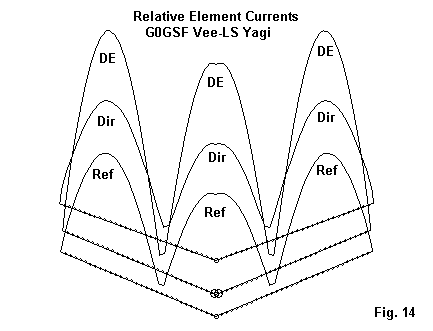
Fig. 15 shows a pattern that corresponds fairly closely to the G0GSF plot, even though its gain is about 0.3 dB higher than my model. Even the lower gain of my model is superior to that of all of the preceding models, although the front-to-back ratio is somewhat lower. The front-to-back ratio is about 17 dB, and the source impedance about 20 + j 20 Ohms, ripe for a Tee or gamma match.

Once full details of the antenna are available to the amateur community, it is likely that we shall see a number of replicas for 6 meters and up. Despite the fact that it does not achieve the pleasant 50-Ohm feedpoint impedance of the Lansdorfer-Sacher Yagi, the simplicity of construction and the freedom from dependence on loading components is likely to make the design attractive.

The result was an array having the description shown below, with all dimensions in fractions of a wavelength rather than in inches, in order to correspond with the description of the G0GSF antenna. Note that the element diameter is smaller, corresponding to about 3/16".
3 el Yagis, fed in phase                     Frequency = 145  MHz.

Wire Loss: Aluminum -- Resistivity = 4E-08 ohm-m, Rel. Perm. = 1

              --------------- WIRES ---------------
Wire Conn.--- End 1 (x,y,z : wl)  Conn.--- End 2 (x,y,z : wl)  Dia(wl) Segs

1         -0.796,  0.000,  0.000        -0.310,  0.000,  0.000 2.30E-03  21
2         -0.788,  0.165,  0.000        -0.317,  0.165,  0.000 2.30E-03  21
3         -0.770,  0.420,  0.000        -0.336,  0.420,  0.000 2.30E-03  21
4          0.310,  0.000,  0.000         0.796,  0.000,  0.000 2.30E-03  21
5          0.317,  0.165,  0.000         0.788,  0.165,  0.000 2.30E-03  21
6          0.336,  0.420,  0.000         0.770,  0.420,  0.000 2.30E-03  21

              -------------- SOURCES --------------
Source    Wire      Wire #/Pct From End 1    Ampl.(V, A)  Phase(Deg.)  Type
          Seg.     Actual      (Specified)

1          11     2 / 50.00   (  2 / 50.00)      1.000       0.000       V
2          11     5 / 50.00   (  5 / 50.00)      1.000       0.000       V

Ground type is Free Space
The spacing between Yagi center lines is about 90" and the total overall width is just under 130". This width is similar to width that the G0GSF antenna would have if its elements had been linear.
The current distribution on the Yagi elements is very similar to that on the outer portions of the G0GSF antenna, as shown in Fig. 17.
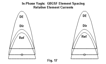
The family resemblance goes further than current distribution. The in- phase-fed Yagis show a free-space gain of nearly 12 dBi (using aluminum elements), with a front-to-back ratio of over 12.7 dB. Each Yagi has a feedpoint impedance of 21.9 + j16.2 Ohms, values similar to the source impedance of the G0GSF antenna. The azimuth pattern appears in Fig. 18.

Several consequences follow from this exercise. First, folks often forget that genetic optimizing algorithms can identify hitherto unused configurations, but so far they have not produced new antenna types. The G0GSF antenna belongs to the general class of EDZ arrays, which are forms of phased Yagi arrays. Second, the Vee-ed elements, while initially appearing to yield significant gains in performance, turn out to be marginal adjuncts compared to comparable arrays with linear elements. At best, Vee-ing the elements permits a slightly improved front-to-back ratio for the array, but the phased Yagi pair has not been fully optimized.
Of course, the use of genetic algorithms is still quite new, and the production of viable designs is a significant achievement for a technique so new. Nonetheless, neither the optimizing technique nor advanced forms of phased arrays--under whatever name they go--should obscure the interrelationship of antenna types.
At the same time, and without fanfare, I modeled these antennas on 2 meters to check out their feasibility at VHF. EDZ-based antennas are often thought of as principally HF antennas of thin wire construction. 3/16" rod construction at 2 meters and above is certainly practical. They are only 6-meter size in side-to-side dimension, and much less in front-to-back size. All of the long elements are easily adjusted for the use of larger diameter tubing. These antenna types may have their niches in the array of available VHF radiators.
Updated 7-28-99, 9-16-99, 4-10-2000. © L. B. Cebik, W4RNL. Data may be used for personal purposes, but may not be reproduced for publication in print or any other medium without permission of the author.