 Feeding the EDZ
In the Summer, 1997, issue of Communications Quarterly, Rick Littlefield, K1BQT, presents a 2-meter EDZ that bears close examination. Besides an interesting construction method, designed to make a very durable EDZ for vertical use in hearing 2-meter repeaters, the key unique feature of Rick's design is the match and feed system that eliminates the usual center inductor to cancel out the heavy capacitive reactance at the feedpoint.
An EDZ at almost any frequency has a variable feedpoint impedance and capacitive reactance, depending on the exact length to which it is cut. However, without altering performance by more than a tenth or so of dB gain, one can cut the antenna for a feedpoint impedance in the 100-140 ohm resistive range, which gives a capacitive reactance in the 500-600 ohm range.
Rick applied a technique used with 5/8 wl vertical gp antennas: instead of an inductor, he uses a length of coax about 10.875" long, with a rod element beyond that point. Let's think of a 5/8 wl vertical and then simply place 2 of them feedpoint to feedpoint to get the final EDZ. The feed goes to the center conductor of the coax length. At the feed end, the braid is not connected to anything. At the far end, the center conductor and the braid are connected together and this junction goes to the 38" rod element. Rick calls this a delay line.
When two of these assemblies are put end to end, the coax center conductors are the two terminals making up the feedpoint. The braid ends are about an inch or two apart (and must NOT be connected together). The result is a nearly purely resistive feedpoint impedance of 100 ohms in the 2-meter model. Rick uses a 75-ohm 1/4 wl (+ 1/2 wl added) to make a combination matching section and balun for a 50-ohm coax feedline.
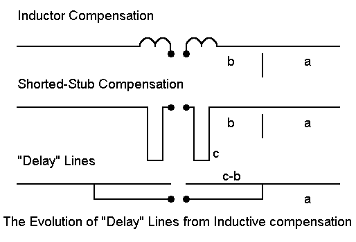
The delay line is interesting, because the name does not describe its function. Actually, it is a simple shorted feedline stub providing the inductive reactance necessary to cancel the antenna's capacitive reactance. Let's look at the figure to see the evolution of the arrangement.

Part A shows the conventional split coil arrangement so familiar to EDZ builders (who do not use either open feedline to an ATU or a stub tuning method for a 50-ohm match). Part B replaces the inductors with a pair of shorted feedline stubs calculated to provide the same inductive reactance as the coil sections. Note that I have designated the outer part of the antenna line as "a" and the inner part as "b" in the sketch. When I substituted the paralel feedline, I designated on side of it as "c." "C" is as long as "b".
There is no rule that says you cannot sometimes make a wire do double duty. There is no incompatibility between wire "c" and wire length "b" so that we can combine them together as in Part C of the sketch. And Part C is essentially the arrangement used in Rick's coax "delay" line. Because the coax is now doing double duty, the exact length may change from simple calculations for stubs, but it is very close.
Although the final arrangement looks like a Tee match, it is not. The center must have a gap, forming at best a split-T top. The open ends of the non-feedpoint center are actually the ends of the inductive stubs away from the feedpoint and thus must be kept independent of each other by a gap.
The use of coax was possible in the original model, because the resistive portion of the feedpoint impedance was near 50 ohms on each side of center (for the 100-ohm total). Hence, the use of 50-ohm coax did not alter the feedpoint impedance.
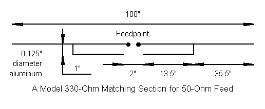
If we use feedlines of higher impedance, two things will happen. First, the feedpoint impedance will be reduced. Second, the length of the stub will increase, placing the junction of "c-b" and "a" farther outward on each side of center. The next figure is a sketch of a model I developed while exploring this subject.

To create as reliable a NEC model as possible, I used 0.125" diameter alumuminum thoughout all parts. This kept the diameter constant, thus allowing a greater reliability of the result with NEC-4. I modeled the parallel lines 1" apart, give about a 330-ohm characteristic impedance for the resultant line. With a connection point about 14.5" outward from center and a 2" gap between the open ends, the stub/line or split-T match provides about 54 ohms resistive impedance and no reactance at the feedpoint. Hence, direct 50-ohm coax feed is now possible.
The revised feed provides both capacitive reactance cancellation and resistive impedance transformation together. The length of the section is about the same as the combination of a 330-ohm shorted stub plus a length of the same line necessary to transform the overall impedance to nearly 50 ohms on its own, although treating this way of looking at the sections as a correct analysis of actions and interactions involved is far from certain at this point.
However, the model's parallel feedline section is close enough to 300 ohms to suggest that experiments may be useful with twinlead, taking into account the line's velocity factor of 0.8, of course. The technique may also be applicable using 450-ohm window line or 600 ohm ladder line, experimentally finding the correct length to use. And the technique is likely applicable at all HF and VHF frequencies at which EDZs are in use.
One advantage of the technique is that it is fairly broadbanded, giving full 2-meter coverage either in Rick's coax version or in the modified parallel line version shown here. I have not explored the consequences of this feed for use of the EDZ as a simple long wire on other HF bands--yet.
Henry Pollock, WB4HFL, took up the challenge of creating a #14 copper wire HF version of the impedance transformation "delay" line EDZ. His initial version was 42' long with 450-ohm match lines either side of center, each 66.5" long. The antenna resonated at 28.9 MHz on this first try. Modeling the exercise suggested that lengthening the antenna a bit (to 44.7') and shortening the match sections to about 65.5" (adjusted after physical modeling for velocity factor) would likely bring the antenna closer to a 28.5 MHz target. The 2:1 SWR bandwidth of the model appears to be about 600 kHz, although the use of a coax feeder will likely widen the bandwidth operationally at the shack end of the line. These figures are not unlike the bandwidth numbers for stub-tuned versions of the EDZ.
As a general rule, lengthening the antenna wire tends to reduce the resistive component of the feedpoint impedance, while lengthening and shortening the match section changes the reactance without affecting the resistance much. In general, it appears that the higher the characteristic impedance of the feedline used to effect the impedance transformation, the narrower the 2:1 SWR bandwidth of the antenna.
So here is one more experimental way to feed an EDZ. The K1BQT and WB4HFL experimental antennas prove that the principle works, yielding an EDZ with no need for stubs or ATUs: matching is built into the antenna structure itself. Have fun creating
some interesting prototype EDZs for 50-ohm feeds.
Updated 8-27-97. © L. B. Cebik, W4RNL. Data may be used for personal purposes, but may not be reproduced for publication in print or any other medium without permission of the author.