
 Part 1:
We are very careless with the ground. We tend to treat it as a single homogenous entity. In simplest terms, that means that we think about the ground in the same way, no matter in what radio context it appears.
We are not as careless as we used to be. When forced by circumstance, we do sort out the following grounds.
G1. The DC and static discharge ground: This is the ground of long ground rods by which we ensure that DC, small static charge build-ups, and power line AC are shunted to ground. Our station ground strap gets into the act here, because we make a common ground for all cases, keeping them at the same potential, hopefully ground potential if our distance from the rod into the earth is not too long.
G2. Circuitry common buss (ground): We have also learned that there is a difference between a circuitry common and an earth ground. Sometimes we have learned this the hard way with shocks and tingles.
G3. Lightning ground: We have also learned that lightning strokes and other sudden high voltage and high current impulses require more attention than G1-type grounds. The details of a satisfactory, equipment-protecting grounding system for lightning are more complex than those required for simply preventing the wind from building a static charge on our dipoles.
G4. RF ground: Effective RF ground also requires attention to many details. Deep rods, while useful, may be less effective as RF grounds than we previously thought, and the U.S. Army developed a system of perimeter straps and a sequence of shorter rods to effect a satisfactory overall station RF ground. RF paths to and from ground via transmission lines, circuitry-to-case connections, common mode paths, and numerous other sources are receiving increased attention both by those who build equipment and by those who assemble operating stations.
We might extend this list--not to mention subdivide it. But let's turn to a couple of new categories created out of one old one. Both have to do with antennas.
We tend to think of the ground relative to an antenna as a single ground. Hence, we tend to lump together the ground from which signals reflect to contribute to antenna far field patterns and the ground directly under a monopole antenna. The "only" difference is their relative distance from the antenna itself. However, let's see where separating the two ideas leads.
G5. Far field reflective ground: The ground quality is usually specified in terms of conductivity (given in Siemens or millisiemens per meter) and a dielectric constant (permitivity). ON4UN did some modeling with some vertical radiators that suggests the ground kicks in as a reflective medium somewhere around 2 and a half wavelengths from the antenna--possibly more for highly elevated antennas. Although the ground immediately under the antenna has some effect on antenna effectiveness relative to far field patterns, the effect is small (unless the ground is needed to complete the antenna). Dipoles, for example, exhibit only small gain changes as the quality of soil is ranged from very poor through very good.
Do not confuse ground quality with terrain considerations. The quality of ground at varying distances from an antenna is only one factor among many with which terrain evaluation is concerned. Slope and interfering objects are samples of other factors that go into terrain evaluation for determining the ultimate elevation pattern for a given antenna and site.
Self-contained vertically polarized antennas, running from the vertical dipole to complex arrays like the bobtail curtain, exhibit the same far field radiation properties with respect to ground as do dipoles and other horizontally polarized antennas at HF. The surface wave of an HF antenna is small, relative to the sky wave. Losses may be slightly higher than with a high horizontal antenna, but generally are not significant.
G6. Antenna-completion ground: Monopole antennas are generally analyzed as having their missing pole (relative to a dipole) within the ground. This is often pictorially presented as an "image" antenna sticking straight into the earth. While this portrayal allows the solution to certain basic equations, it is actually a very poor picture of what is going on.
It is the surface volume of the ground that provides the completion of the antenna. Signals penetrate the ground to depths that vary directly with wavelength and inversely with frequency. However, even with a monopole, the penetration does not act like a spear into the ground.
A more correct picture is a surface area (with some depth) around the monopole. The conventional radius of this surface is about 1/4 wl. Since even the best soil is lossy compared to conductors, we lay screens and radials under the soil to improve its conductivity. Somewhere between 60 and 120 radials approaches the conductor saturation point of most soils. This is the most traditional ground plane.
Of course, we can also elevate the ground plane. A number of investigators (nicely referenced by ON4UN) have discovered that even a few feet of elevation can improve the performance of a monopole over that obtainable with buried radials.
Another interesting phenomenon is that rooftop monopole vertical antennas do not seem to benefit from littering the roof with 60 to 120 radials. 4 to 8 seems to be enough to achieve all the performance of which the antenna design is capable.
Let's add one more phenomenon: Experimenters have discovered that the best length for radials is slightly less than 1/4 wl. Of course, these were elevated radials.
And one more: If we model a monopole with radials in free space, it does not care what its orientation is.
If we construct a monopole with the feedpoint high, and then if we add another monopole atop the first, we have a vertical dipole. Now let us shorten the upper monopole and compensate with a hat. A hat is a symmetrical array of wires ranging from 2 to very many, with or without a perimeter ring or inner rings. Its function is to complete the current path necessary to achieve some specified state at the feedpoint, usually resonance. We used to call this a "capacity" hat based on the way we calculated its size at LF and VLF, but those methods go to pot at HF. (I know this from having written a very convoluted program to calculate them from 3 to 30 MHz for antenna length reduction only down to 70% full size.) So let's just call our structure a hat. Because it is at right angles to the antenna, and because it is symmetrical, it ideally does not radiate. All the field from one leg is cancelled by a field equal in magnitude but opposite in phase from an opposing leg.
Now continue to shorten the upper monopole until it is very short, perhaps even insignificantly short. The hat has to grow in order to provide an ever longer current path to maintain resonance (or some other specified condition) at the feedpoint. In fact the hat grows to nearly 1/4 wl in radius. Since it is a very fat wire indeed, it does not grow to a full 1/4 wl.
What we have is an upside down conventional monopole. Turn it right side up at many wl above the ground, and the far field pattern is indistinguishable from the upside down version. Tilt the legs making up the hat, and they are no longer at right angles to the single-wire monopole end: hence, they partially radiate and partially cancel--as every maker of simple 2-meter sloping GP antennas knows. Upside down, we called the structure a hat; rightside up, we call it a ground plane. The antenna does not care because an antenna-completing structure by any other name performs just as sweetly.
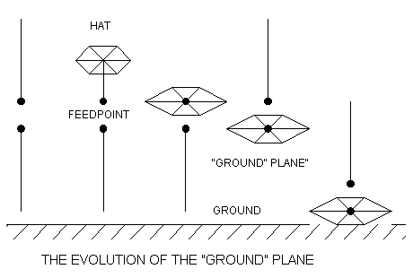
Now bring the antenna closer to the dirt ground. The fields from the hat-plane begin intersecting the ground in earnest, and those intersections yield interactions that may alter the required size of the hat-plane. But the basic function of the hat-plane is to complete the antenna. In short, the antenna-completing ground is not a ground at all.
Instead, we sometimes use the ground to do the work of the hat-plane. More precisely, we have used the conductivity of dirt ground materials to do the work of the hat plane. Everyone who has ground-mounted a vertical in the middle of a septic tank drain field has gotten decent performance without radials.
So, what about that class of self-contained vertically polarized wire antennas (SLVs)? This group includes a number of 1 wl loop and open antennas, such as the delta, the square, the rectangle, and the half- square. All these antennas produce vertically polarized radiation independently of the dirt ground by virtue of the fact that part of the antenna structure acts as a phasing line in which horizontal structure radiation is cancelled, while radiation from the vertical elements is phased for additive field production.
SLVs model nicely in free space with properties that carry over into models and real antennas mounted several wavelengths above ground. Up and down make no difference to these antennas under the given conditions. Such antennas depend only on the far field reflective ground with respect to their patterns.
Brought closer to the dirt ground--which is inevitable when we use SLVs on the lower HF bands--the antenna fields intersect with the "semi-conductive" ground materials--just as they might if we sandwiched one of the antennas between two sheets of metal. The results are modifications to antenna performance. But, the antenna does not depend upon the ground for its basic performance as an antenna--that is, the ground does not complete the antenna. The ground is not a ground plane.
In fact, the so-called ground plane is never a GROUND plane, but always a hat-plane. Hence, the so-called antenna-completing ground is not a ground at all--even though we sometimes use the ground to do the work of the plane. This is not the first time we have misnamed something in radio. It took a long time to weed out the term "condenser." It will likely take even longer to drop the term "ground" from ground plane.
But do we not always connect the braid of the coax to the plane and the center to the monopole? Most of us do, but it is not required if we separate our DC and RF grounds from the antenna end of the transmission line. We can feed a monopole through an inductively coupled balanced ATU and then connect either side of the line to either antenna terminal. Once again, we collect a number of functions into a single configuration, like connecting the case to the coax braid and the braid to the monopole ground rod as our station ground: then we forget to sort out the functions, and the configuration makes it hard to separate them. Nonetheless, the antenna, as an antenna alone, does not need a ground for its ground plane. (But add one anyway for lightning, static discharge, RF, and DC grounding.)
By sorting out our grounds--and further sorting real grounds from planes we only call grounds--we can achieve a better understanding of a. how monopoles work and b. why some vertically polarized antennas do not need a ground plane. But I doubt if the term "hat-plane" will ever gain currency.
Eventually, we shall add pictures and quantifications to these initial
notes. Nonetheless, I hope they prove useful as a start in sorting out the
many grounds of radio work, especially if you, like Karl Mannheim, ever
say, "Ich habe meine Grunde vergessen." ("I forgot where I started.")
Updated 5-20-97. © L. B. Cebik, W4RNL. Data may be used for personal purposes, but may not be reproduced for publication in print or any other medium without permission of the author.