 Part 2:
A true hat is a symmetrical conductive structure that we place on the end of an antenna element, and at right angles to it, so that two effects occur. First, the net radiation from the hat is zero, due to the cancellation of radiation from one part of the structure by that from another part. Second, by using the hat as a path for antenna currents, we may shorten the main element length and still achieve resonance or some other specified condition.
We may also use slightly non-symmetrical structures to achieve, what is usually called top-loading. So long as the structure does not radiate a field more than about -30 Db relative to the field from the main element, the radiation from the field will not materially affect the overall pattern or the feedpoint impedance of the antenna. Non-symmetrical top loading may, however, have an affect on the operating bandwidth and gain of the antenna element.
Although we refer to these methods as top-loading, they are quite distinct from base or mid-element loading. All the two forms of loading have in common is that they allow us to use a shorter main element in our antenna. Base-loading and mid-element loading normally use either solenoid inductors or shorted transmission line stubs to introduce into the antenna an inductive reactance that compensates for the capacitive reactance that emerges as the element is shortened. Inductive reactance comes at the cost of resistance that transforms some of the energy reaching the antenna into heat. Every mode of inductive loading, including the use of inductive transmission line stubs, has a finite Q, and that means a source of gain loss in addition to the loss of gain which is natural to the shortening of an antenna element.
A hat is simply a form of antenna length completion so that the current has a path of a correct length to achieve resonance, despite the use of a shortened main element. The only losses are those associated with the shortening of the element and the materials used to construct the hat.
From the perspective of modeling, we may drop the word "capacitive" when referring to hats. That term arose from a method of calculating the size of hats for LF and VLF and rests on using an open transmission line analogy for antennas. From the beginning, the technique was considered only an approximation, and it breaks down severely at HF, where the diameter and relatively uniform diameter of antenna elements violates the fundamental terms of the analogy. Hence, from this point forward, I shall simply refer to hats or top hats.
We may construct hat structures in many forms. The most common form is a series of radials extending from the end of the main element outward. The radials are spaced at equal angles to each other. Hats require a minimum of 2 opposing radials, but may have any large number until they form a solid disk. Along the way, we shall examine an alternative to this structure that has some interesting properties.
The length of a hat radial (or "spoke," as it is sometimes informally called) depends on many variables: the length of the main element relative to the frequency of interest, the diameter of the main element, the diameter of the radial wire, and the number of radials. Let's freeze the element and radial diameters for a moment at 2" and 0.25" respectively, and let's make them aluminum. That will simplify some modeling exercises by not varying everything at the same time. Let's also make our frequency of interest 7.05 MHz.

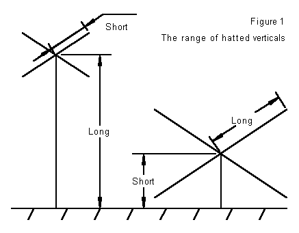
We shall start with the arrangement shown in Figure 1. Here we have a vertical monopole atop perfect ground. We shall use a top hat consisting of 4 spokes, and then shorten the antenna 10% at a time and see what length the spokes must be to reresonate the antenna. Gain and feedpoint impedance figures are included to see what shortening the element does to them.
Length (%)     Length (ft)    Radial         Gain (dBi)     Feedpoint Z
                              Length (ft)                   (R +/- jX ohms)
100%           33.25          ---            5.14           35.97 - 0.63
 90%           29.925          2.060         5.13           35.19 + 0.70
 80%           26.6            3.800         5.08           32.76 - 0.66
 70%           23.275          5.570         5.02           29.08 - 0.71
 60%           19.95           7.600         4.96           24.34 + 0.13
 50%           16.625          9.900         4.88           18.81 - 0.66
 40%           13.3           12.700         4.80           13.07 + 0.19
 30%            9.975         16.100         4.71            7.83 - 0.42
 20%            6.65          20.700         4.59            3.67 - 0.62
 10%            3.325         27.100         4.29            1.00 - 0.42
Although the shortening progresses linearly, the rate of decrease in gain and feedpoint impedance increases more rapidly past the 70% mark. Historically, commercial antenna engineers have used 2/3 full size as a bench mark for minimum efficient antenna operation. However, the gain over a perfect ground decreases by less than a full dB down to the 10% mark, making very short amateur antennas feasible, if the feedpoint impedance can be overcome.
The use of hats is not restricted to vertical monopoles. We may employ them on dipoles with equal results. NEC programs model vertical monopoles over perfect ground by the use of the antenna image, essentially a copy of the antenna below the ground level. If we move each of these resonant antennas along with its image into free space, we obtain a resonant dipole whose feedpoint impedance is simple twice the figure for the monopole. Gain reductions will parallel those for the vertical monopole (although starting in the vicinity of about 2.13 dBi in free space for the dipole). In the end, a short dipole with a hat on either end will still have very usable gain. A 2-element Yagi with hatted elements about 70% full-size will rival its full-size cousin in both gain and front-to-back ratio, although the feedpoint impedance will be lower. Indeed, the failure of the hatted 2-element Yagi to achieve the kinds of front-to-back ratio that are achieved by linear and coil loaded Yagis is further evidence of the difference between the two routes to shorter elements.
Hat spoke length decreases as we add more radials to the structure. If we double to number of radials to 8 with the same main antenna, here is what we get.
Length (%)     Length (ft)    Radial         Gain (dBi)     Feedpoint Z
                              Length (ft)                   (R +/- jX ohms)
100%           33.25          ---            5.14           35.97 - 0.63
 90%           29.925          1.505         5.13           35.18 - 0.06
 80%           26.6            2.730         5.08           32.84 - 0.40
 70%           23.275          4.000         5.03           29.27 + 0.23
 60%           19.95           5.400         4.97           24.49 + 0.73
 50%           16.625          7.000         4.90           18.87 - 0.02
 40%           13.3            9.000         4.83           13.10 - 0.45
 30%            9.975         11.650         4.77            7.81 - 0.61
 20%            6.65          15.500         4.69            3.62 - 0.03
 10%            3.325         22.000         4.52            0.95 - 0.20
There are several things to notice about this table. First, radial lengths range from about 75% to 80% of those required for a 4-radial hat. Second, there is no significant change in gain between the two hat sizes until the antenna length is less than 70% full-size. At shorter lengths, hats with more radials yield slightly higher gains, but that advantage quickly diminishes to the level of the unnoticeable. Third, the feedpoint impedance does not change as the number of radials in a hat increase; it is a function of the main antenna element length.
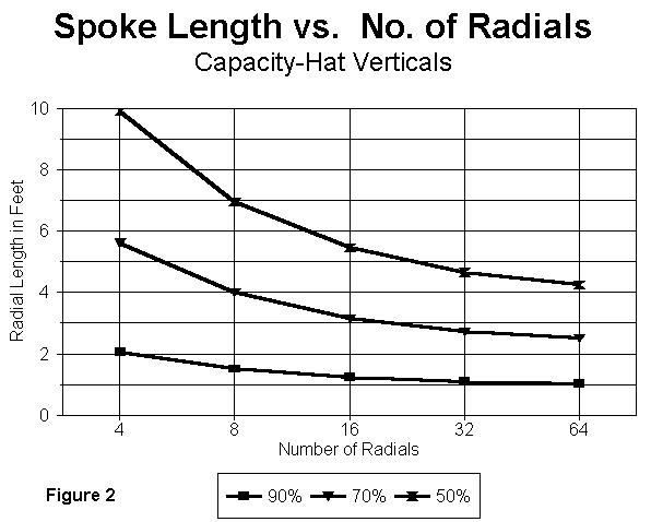
We can plot the decrease in radial length with the increasing number of radials more readily by spot checking antenna. The following three tables use antenna elements of 90, 70, and 50 percent full size (2" diameter aluminum) with 0.25" hat radials that double with each step.
Length         Number         Radial         Gain (dBi)     Feedpoint Z
(% and ft)     of Radials     Length (ft)                   (R +/- jX ohms)
 90% 29.925     4              2.060         5.13           35.18 - 0.06
                8              1.505         5.13           35.18 - 0.06
               16              1.235         5.13           35.21 + 0.10
               32              1.090         5.13           35.19 - 0.19
               64              1.022         5.13           35.19 - 0.07

Length         Number         Radial         Gain (dBi)     Feedpoint Z
(% and ft)     of Radials     Length (ft)                   (R +/- jX ohms)
 70% 23.275     4              5.620         5.02           29.24 + 0.57
                8              4.000         5.03           29.35 + 0.82
               16              3.150         5.03           29.35 + 0.48
               32              2.720         5.03           29.32 + 0.12
               64              2.500         5.03           29.25 - 0.52

Length         Number         Radial         Gain (dBi)     Feedpoint Z
(% and ft)     of Radials     Length (ft)                   (R +/- jX ohms)
 50% 16.625     4              9.900         4.88           18.81 + 0.66
                8              6.950         4.90           18.86 - 0.31
               16              5.450         4.91           18.98 + 0.66
               32              4.650         4.91           18.99 + 0.29
               64              4.250         4.91           19.00 + 0.12
I would have carried the exercise out to 128 radials, except for three factors. First, even with the shortest antenna element, the gain and feedpoint impedance values had stabilized well before the 64-radial mark. Second, a well-converged model for the 50% full size 64-radial antenna had already exceeded 1,000 segments. And third (the reason I did not have to run the big model more than once), the radial lengths for larger arrays are completely predictable.

Figure 2 is a graph of the values charted above. If you examine the data by taking the decrease in length for each doubling of the number of radials, you will discover that for each doubling, the length decrease halves. The 50% model with 128 radials will therefore have radials just about 4.05' long. (Moreover, we already know the antenna gain and feedpoint impedance.) The exact increment to be halved with each step will, of course, vary as we change the diameters of the main element and of the radials.
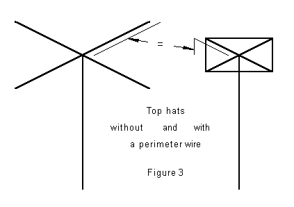
There is a second popular way to construct top hats. Instead of using radials alone, we may use radials and connect them together with a perimeter wire. Figure 3 illustrates the difference. With a perimeter wire, the required length of the radials decreases significantly. In the table below are figures for a 4-radial assembly with a perimeter wire. Compare the radial lengths with those required by the radial-only structure.

Length (%)     Length (ft)    Radial         Gain (dBi)     Feedpoint Z
                              Length (ft)                   (R +/- jX ohms)
100%           33.25          ---            5.14           35.97 - 0.63
 90%           29.925          1.320         5.13           35.17 - 0.11
 80%           26.6            2.380         5.05           33.02 + 0.62
 70%           23.275          3.400         5.03           29.29 + 0.19
 60%           19.95           4.500         4.96           24.38 - 0.91
 50%           16.625          5.800         4.90           18.89 - 0.15
 40%           13.3            7.350         4.83           13.15 + 0.28
 30%            9.975          9.200         4.76            7.83 + 0.05
 20%            6.65          11.400         4.68            3.62 - 0.94
 10%            3.325         24.400         4.45            0.96 + 0.43
Compared to the spoke-only version of the 4-radial top hat, the radial + perimeter model creates no changes in feedpoint impedance. The slightly elevated gains of the perimeter model suggest that adding the outer wire allows the hat to perform with an equivalence to a hat with twice the number of radials. Finally, required spoke length of the hat decreases more rapidly as the antenna is shortened. The degree of shortening decreases as the basic number of radials is increased, but never diminishes to zero.
The use of a perimeter wire permits more compact hat structures than are possible with the open radial structure. However, no weight savings are gathered this way. In very approximate terms, the current path for a perimeter model is equal to the length of the radial plus one-half the length of the perimeter segment to the next radial. Hence, one will use more wire in the perimeter version, but will be able to place it more securely closer to the main element.
Understanding the behavior of top hats is important in itself, since hatted vertical monopoles are growing more common as hams use ingenuity in finding ways to support such structures and as they learn of the reduced losses and wider operating bandwidth possible with such antennas in comparison to base-loaded verticals. Moreover, since we have finally learned that hats are simply antenna current pathways and not capacitor plates, we may be in a position to use them wisely in dipole assemblies (both vertical and horizontal.
However, for our purposes, a short study of hats is a preliminary to
inverting them to form planes--which we are ready to do, if you will join
me in free space.
Updated 5-20-97. © L. B. Cebik, W4RNL. Data may be used for personal purposes, but may not be reproduced for publication in print or any other medium without permission of the author.