 ANTENNAS FROM THE GROUND UP
Last time, we examined the performance of vertically oriented, horizontally polarized 1-wl loops (VOHPLs) on their fundamental frequency. We chose 40-meter loops to study, since they are generally the most practical. As with almost everything we have noted about antennas, the information applies to other bands with appropriate scaling, especially of heights above ground in terms of fractions of a wavelength.
However, many would-be loop builders want to use VOHPLs on frequencies above their fundamental. With parallel transmission line and an ATU, multiband operation is certainly possible. The key question is this: what do we get for our trouble? And how does it stack up against other possible multiband antennas. We have already examined the 135' center-fed antenna, the 102' center-fed antenna, the 135' end-fed Zepp, and the 135' off- center-fed antenna. The compendiums of patterns for these antennas will make excellent comparative references for you as you try to decide which multiband wire to build. Developing this reference library of patterns and data is one of the reasons for this series.
For the VOHPLs, we shall vary the procedure used for the other antennas. There are simply too many variants to analyze one pattern at a time. Therefore, we shall begin with a collection of types of patterns that occur on various bands with the VOHPLs, labeling each with a letter. Then, we shall tabulate the modeling results for each type of VOHPL on each band, referring to a pattern by letter (if one exists in our collection). We shall also list other data, such as maximum gain, elevation angle of maximum radiation, and approximate feedpoint impedance. All antennas (except the equilateral delta) will have a maximum top wire height of 40' as representative of a typical backyard ham installation. All the modeled data emerge from EZNEC with models constructed of #14 copper wire over medium ground.
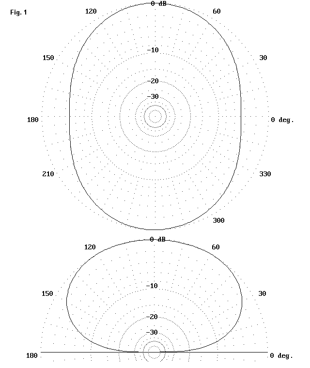
A1: Rounded Oval

The width of the azimuth oval may vary widely, depending upon frequency and antenna configuration. When the side rejection increases sufficiently, the pattern takes on the look of the next pattern, A2.
A2: Peanut

The side rejection does not exceed the amount shown here for any of the models given below.
B: High Oval

The width of the azimuth oval is a product of using an elevation angle of 45 degrees. High ovals have maximum radiation angles of 65 degrees to 90 degrees and the base bulges may vary in shape.
C1: Very Small Wings

This patterns shows the beginnings of side wings due to radiation from the vertical wire segments.
C2: Large Smooth Wings

The radiation is now predominantly off the edges of the antenna. The structure of the elevation pattern■s lower angle lobes may vary from one band to another.
C3: High-Angle Wings

The lowest elevation angle pattern details may vary. The wing structure, however, ranges from about 35 degrees to 60 degrees from one instance to another.
Virtually all of the radiation patterns of 1 wl VOHPLs will fit one of these general patterns, although gain and precise elevation angle of maximum radiation will vary widely. The following tables for two deltas and two rectangles provide data on take-off angle, maximum gain, approximate feedpoint impedance, and pattern type. The diamond is omitted due to its size.
1. Right-Angle Delta

Freq. TO Gain Impedance Ptn MHz Ang dBi R ˝ jX 10.1 55 5.2 2000+j2500 A1 14.15 90 6.3 150-j90 B 18.1 67 8.0 1100-j850 A1 21.15 49 7.2 200-j10 C1 24.95 90 8.4 1800-j1900 B 28.5 72 6.4 400+j20 C3
2. Equilateral Delta

Freq. TO Gain Impedance Ptn MHz Ang dBi R ˝ jX 10.1 37 4.6 1400+j3900 A2 14.15 90 5.2 350+j50 B 18.1 52 7.3 1100-j1400 A1 21.15 90 5.5 150+j150 C2 24.95 69 8.8 1000-j800 B 28.5 50 5.9 350+j400 C3
3. Square Quad Loop

Freq. TO Gain Impedance Ptn MHz Ang dBi R ˝ jX 10.1 36 4.6 4000+j1900 A2 14.15 90 0.8 300+j160 B 18.1 90 4.3 900-j1500 B 21.15 32 4.7 350+j50 C2 24.95 90 2.9 1000-j1500 B* 28.5 45 7.0 400+j220 C3
*This pattern is stretched to the side so that maximum radiation is off the antenna edges.
4. Rectangular Quad Loop

Freq. TO Gain Impedance Ptn MHz Ang dBi R ˝ jX 10.1 42 5.9 2500+j1100 A1 14.15 90 2.8 150-j210 B 18.1 43 7.2 3600-j1000 A2 21.15 19 7.7 130-j350 C2 24.95 39 5.7 2100+j950 A1 28.5 37 7.0 330-j170 C3
All of the antennas modeled had peak top-wire heights of 40' except the equilateral delta. Because of its vertical size, its bottom wire was placed 8.4' above ground with an apex height of 50'. The square quad loop's bottom wire is an unnaturally low 3.85' above ground to set the top wire at 40'.
In order to evaluate the overall pattern of the data, we need a reference standard. Since we have not presented the data for the 40-meter dipole at 40', let's use it for reference. Patterns will resemble those of half their frequency in the set for the center-fed 135' wire.

Freq. TO Gain Impedance Ptn MHz Ang dBi R ˝ jX 7.15 50 5.9 90+j9 A1 10.1 34 7.0 300+j750 A2 14.15 24 9.5 6000-j600 A2* 18.1 19 10.0 180-j900 D 21.15 16 7.8 100-j130 E 24.95 14 8.8 390+j750 F 28.5 12 9.4 3400+j700 F
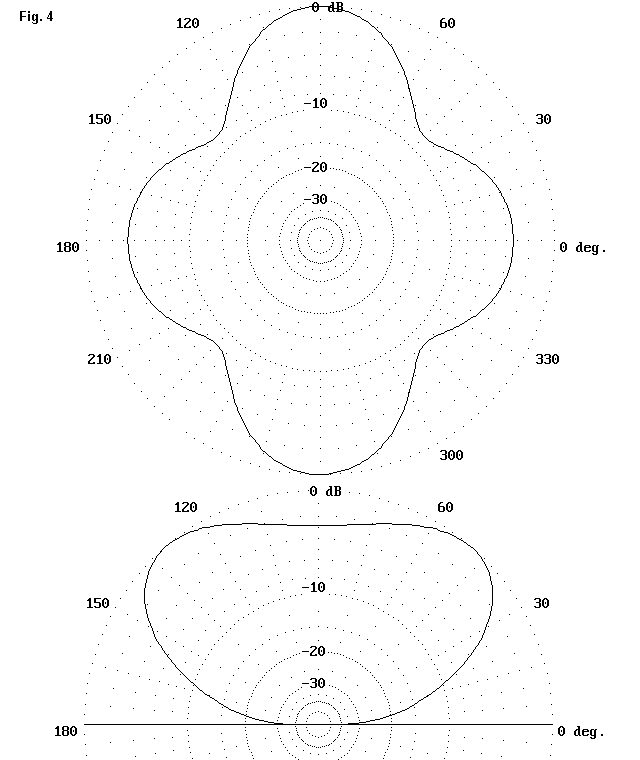
Pattern A2, flagged for 14.15 MHz, is a peanut with a narrow bandwidth. Pattern D is the typical extended double Zepp pattern, which resembles a peanut with ears. Pattern E has six major lobes, while pattern F has four major lobes.
Pattern D

Pattern E (elevation pattern not shown)

Pattern F (elevation pattern not shown; this is the 28.5 MHz pattern.)

The high feedpoint impedances presented at 14.15 MHz and 28.5 MHz result from the fact that the antenna is an even number of 1/2 wavelengths long at these frequencies. Nonetheless, the antenna is notable for the smooth drop in the angle of maximum radiation as the frequency increases. With few exceptions, the 40-meter dipole at 40' has a lower take-off angle and more gain at any frequency than any of the loops.
All of the loops show high oval patterns on several bands. The high oval pattern indicates that maximum power is being radiated directly or nearly directly upward, as if the loop wires formed a beam antenna in that direction. In fact, that is just what is happening. Wherever the tables indicate a high oval pattern, the ground is acting as an additional reflector element, and radiation is concentrated upward. Reflections alter the phase angles of the top and bottom wires so that they act as a driven element and a director to enhance--in an inefficient manner--the skyward directivity of the antenna.
If we rotated the axis of the antenna to make it a horizontally oriented horizontally polarized loop, we could cut the wire in the middle of each side and insert a small insulator. VK2ABQ used a button for his antenna of this sort. Without further adjustment of wire length or spacing, the antenna becomes directional on its fundamental frequency. It is the forerunner of the Moxon rectangle.
The 1 wl loop, then, is sensitive to certain changes that can alter its overall pattern of radiation. In use on lower HF bands, a VOHPL is necessarily close to the ground, which affects the radiation pattern, directing it nearly straight up on many frequencies. Elevated by 10 wl, in models and actual VHF antennas, the antenna loses much of the near ground effect and radiates more nearly broadside to the loop. Unfortunately, lower HF band users do not normally have the ability to elevate an antenna 10 wl above the ground.
A 40-meter 1-wl loop will make contacts and be a quiet antenna on all bands. However, its performance leaves much to be desired on frequencies above the fundamental. In most configurations on most bands, it is far from a DXer's dream. But the loop can be transformed into a decent DX antenna with only one small change--which we shall make next time.
Updated 11-1-99. ę L. B. Cebik, W4RNL. Data may be used for personal purposes, but may not be reproduced for publication in print or any other medium without permission of the author.