

Very effective antennas do not have to be exceptionally large or expensive. The latest designs and construction methods have their advantages--and also their costs. They tend to obscure some older designs of high merit as we forget to remember them.
Rotatable antennas are very effective, but for those unwilling or unable to put a tower, rotator, and sizable aluminum structure in the air, fixed position wire arrays can provide excellent gain. Most designs are bi- directional, but the side rejection is often sufficient to eliminate most QRM. If we have the trees or the poles to support the ends, and if we take the trouble to align the antenna in the most favorable directions for our intended operation, a wire array can work wonders. For example, a great circle drawn through my QTH in Tennessee with one end in VK-ZL land will have its other end in Europe. A bi-directional array might be just the ticket for much of my operating.
Many broadside arrays are flat-tops--that is, they require at least two wires with considerable horizontal space between them. For most purposes, I would need 4 supports. However, a design that has been around since wire became popular is the Lazy-H, a vertical stack of two wires fed in phase. The standard Lazy-H consisted of two 1 wl wires spaced 1/2 wl apart and elevated so that the lower wire was 1/2 wl above ground.
John Schultz, W2EEY, wrote in the November, 1968, CQ of the "Expanded Lazy-H Antenna." Bill Orr, W6SAI, recalled this antenna in one of his many columns during the 1980s. Another 15 years has gone by, so let's recall this effective array one more time. The key to expanding the Lazy-H is to increase both the horizontal and vertical dimensions by just a little bit.
If we increase the wire lengths from 1 wl to 1.25 wl, we have stacked extended double Zepps in our Lazy-H. The effect is to give us a bit more gain per wire and a significant amount more from the pair. Then, if we increase the spacing from 1/2 wl to 5/8 wl, we achieve approximately the maximum stacked gain possible with two simple wires.
Now, let's build one of these expanded Lazy-Hs for 10 meters.
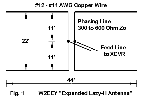
Fig. 1 shows the antenna outline. For 10 meters, a length of 44' per wire is satisfactory and not critical: 40' to 50' will work, but the pattern on 10 meter begins to split up as we lengthen the antenna too far beyond 1.25 WL. Vertical spacing between the two wires need not be too fussy, but the recommended 22' gives us not only 5/8 wl at 10 meters but a usable spacing at other frequencies.
The recommended minimum of 1/2 wl at 10 meters is a bit low for optimal performance. I would recommend that a lower-wire height of about 44' be used, which places the top wire at 66' up. Lower heights will reduce the gain and elevate the TO angle from the figures I shall present as we think about this simple array.
The mechanical beauty of the Lazy-H design is that it requires only two supports--although fairly tall ones. The electrical beauty of the antenna is that it provides excellent bi-directional performance from 10 meters through at least 17 meters, with good performance down to 30 meters. It can also be pressed into service on 40 meters without much difficulty.
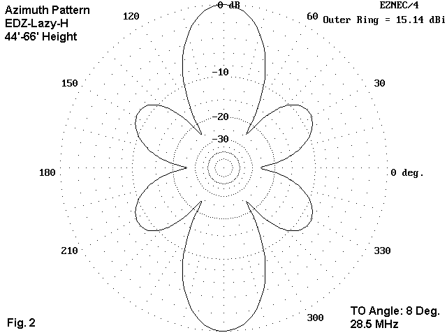
Fig. 2 shows the azimuth pattern of the antenna on 10 meters at an elevation angle of 8 degrees. The phase-fed array still retains the EDZ "ears." These ears are the beginnings of the multi-lobe pattern that emerges as the antenna wire length grows toward the 1.5 wl mark.
On all bands below 10 meters, the length of the antenna is under the EDZ mark, so the pattern is bi-directional with single lobes each way. In fact, at 15 meters, the antenna becomes a standard Lazy-H: two 1 wl wires spaced 1/2 wl apart vertically.
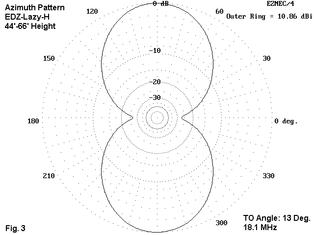
In Fig. 3, we see the 17-meter pattern at its elevation angle of maximum radiation of 13 degrees. As the tables below will show, the lobes become wider as we reduce frequency and narrower as we increase frequency.
For a more systematic view of anticipated performance on all of the possible bands on which we might use this one Lazy-H, here is a table of modeled performance over average ground, with the lower wire 44' up. The table lists the usual gain and TO angle data, but also adds numbers for the vertical and horizontal beamwidths between the -3 dB (half-power) points. This date is useful in determining the azimuth coverage of the antenna in each direction and in estimating the elevation angles to catch the skip for varying circumstances.
Freq      Max. Gain      TO angle       Vert. BW       Hor. BW
MHz       dBi            degrees        degrees        degrees
28.5      15.1            8              9             31
24.9      14.6           10             11             41
21.2      12.5           11             12             52
18.1      10.9           13             14             61
14.15      9.0           17             18             73
10.1       8.1           24             27             85
 7.15      6.4           33             44             99
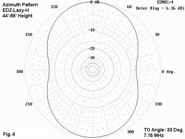
By the time the antenna's operating frequency is lowered to 40 meters, the pattern becomes a broad oval with a fairly high TO angle, as shown in Fig. 4. However, sufficient radiation occurs at lower angles to make it usable for general purpose communications on that band.
How good is the antenna's performance? I could use any number of comparators here, but the simplest would be a single 44' wire placed 66' up in height, the same height as the top wire of the array. The usefulness of this comparison is that it helps reveal something of the array's characteristics.
Freq      Max. Gain      TO angle       Feedpoint Z
MHz       dBi            degrees        R +/- jX Ohms
28.5      10.5            7              150 - j 695
24.9      10.4            8              620 - j1700
21.2       9.0           10             4200 + j 850
18.1       8.6           12              835 + j1560
14.15      7.7           15              190 + j 490
10.1       7.6           20*              56 - j 105
 7.15      7.0*          29*              24 - j 600
The starred gain entry for 40 meters indicates that the single wire at this frequency shows more gain than the array (by about 0.6 dB). In the TO angle column, the starred entries indicate that the single wire shows a significantly lower angle than shown for the array. Both phenomena are related. The array elevation angle of maximum radiation is a composite from radiation from both wires, with the lower wire radiation raising the angle of the final composite pattern. The difference is slight until the very lowest bands on which we might press this antenna into service. On 40 meters, the lower wire is just over 1/4 wl above ground, so that it raises the overall pattern angle of the array by a goodly amount and provides slightly less gain than the single wire that is about 1/2 wl up.
From 20 meters on up, the Expanded Lazy-H shows good gain over a single wire. The benefits increase the higher one goes in frequency, up to the break-up of the pattern when the wires are longer than 1.25 wl. It is certainly possible to scale the antenna for maximum benefits at a lower frequency, but that lower frequency of maximum gain will become the highest frequency at which one can use the array and still have a bi-directional pattern with a single main lobe off each side of the wires.
The single 44' wire also shows a wide variation in feedpoint impedance according to the length of the wire. The 10-meter value is typical for an EDZ. The 15-meter value is also typical, but of a 1 wl center-fed wire. Parallel feeders and a highly competent antenna tuner would be needed for this antenna. However, careful analysis of the impedance excursions along the chosen feedline can minimize the chances that the tuner antenna terminals will see either a resistance or a reactance value outside its range of adjustment.
So far, I have given no figures for the feedpoint impedance of the Expanded Lazy-H. The two elements in Fig. 1 are fed in phase by the simple expedient of using equal lengths (11') of line to a center point to which we attach the parallel feeders going to the antenna tuner. There are two controllable variables that will affect the feedpoint impedance at the junction with the main line to the shack. One is the length of the lines, which we have set at 11' each. The other is the characteristic impedance and velocity factor of the phasing lines. I shall not here explore other phasing line lengths, but instead shall show some anticipated feedpoint impedances for each band using three different phasing lines. One will be a 450-Ohm, 0.95 VF line, typical of windowed vinyl-covered lines. Another will be 300-Ohm, 0.8 VF line, typical of good quality TV line. The third will be 600-Ohm, 1.0 VF line, which might be bought or built from wire and spacers.
                    Feedpoint Impedance (R +/- jX Ohms)
Freq      450-Ohm             300-Ohm             600-Ohm
MHz       0.95 VF             0.8 VF              1.0 VF
28.5       65 + j 425         115 + j 570          105 + j 610
24.9       17 + j 115*         11 + j 140*          30 + j 140
21.2       22 - j  15*         10 + j  38*          40 - j  50
18.1       45 - j 125          16 - j  26*          90 - j 230
14.15     385 - j 395          75 - j 150         1050 - j 350
10.1       50 + j 105          40 + j  65           50 + j 155
 7.15      10 - j  95*          6 - j  80*          13 - j  90*
Starred entries represent very low resistive components to the feedpoint impedance which might present larger excursions along whatever line is chosen as the main feedline to the shack. Note that the starred entries are fewest with the 600-Ohm phasing line. Once more, it is worth noting that these numbers are derived for general guidance from models. Variations will emerge from the actual construction of the antenna and from conditions and clutter at the antenna site.
One question that almost always emerges with respect to comparing the single wire and the array gain figures for 10 meters is this: how can the array deliver over 4.5 dB gain over the single wire? The answer is straightforward if we compare elevation patterns for the two antennas. Fig. 5 tells the tale.
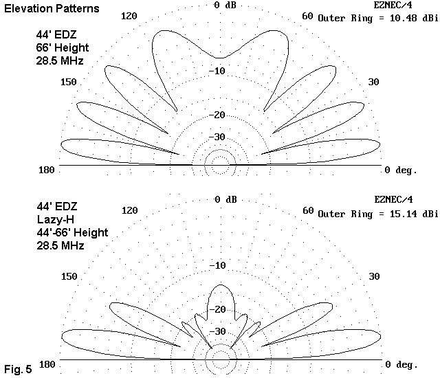
Like any single-wire antenna, the EDZ at 66' on 10 meters shows an array of nearly equal-strength vertical lobes: 4 to be exact. In contrast, the upper lobes of the Expanded Lazy-H are suppressed leaving a single dominant lobe and a secondary lobe well over 4 dB weaker. All other lobes are down by 12 dB or more. The array tends to waste far less power at very high angles of radiation compared to the single wire. This comparative pattern, with variations, tends to hold true down through 20 meters.
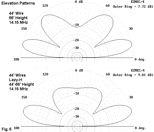
On 20, the effect is less pronounced but still easily measured, as shown in Fig. 6. The area enclosed by the upper lobes of the single wire at the top of the figure is distinctly greater by a considerable margin than the area enclosed by the upper lobe (barely discernable as a double lobe) of the array. The difference in area (assuming that the azimuth patterns are comparable, as they happen to be in this case) is a rough measure of the added power appearing in the lower lobes. In this case, that additional power shows up not only in the maximum gain, but as well in the vertical beamwidth. The phased feeding of vertically stacked horizontal wires has benefits hard to match in a typical flat-top wire array.
Along side the benefits come some limitations. The Lazy-H requires a pair of tall supports and is suited to the antenna farm with more tall trees than money. It is possible to lay out more than one of these inexpensive antennas in order to cover additional regions along the horizon. It is likely that no special treatment will be needed to detune unused arrays to prevent them from altering the pattern of the array in use. Either leaving the shack end of the unused feedline open or shorting it will introduce to the wire feedpoints sufficient reactance to detune the wires. However, this is a facet of multiple array installation that the builder should keep in mind. Sometimes Murphy dictates that nothing will work to prevent interaction short of greater physical separation of the arrays.
The Expanded Lazy-H is an outstanding bi-directional array for 10 meters in the design given here. Its performance holds up well down through 20 meters, and we can press it into service on lower bands. It takes up very little room horizontally in the yard, although a couple of optimally spaced tall trees certainly can aid the installation process. The wires for the elements and the phasing lines, as well as the feedline to the shack and the UV-resistant support ropes, are certainly inexpensive compared to the cost of a tower, rotator, coax, and commercial aluminum antenna. It is a design worth recollecting every 15 years or so just to make sure that we do not forget it.
Updated 4-5-99. © L. B. Cebik, W4RNL. This item first appeared in AntenneX, Mar., 1999. Data may be used for personal purposes, but may not be reproduced for publication in print or any other medium without permission of the author.