 Part III: The Output Story
First, before we jump into these output side circuit variations, let's again reset the parameters of our initial ongoing problem that we initiated in Part 1 and continued in Part II. We wanted a tuner for 7 MHz and chose from a list of recommended values a secondary inductor of 12 micro-H (with a reactance of 528 ohms at that frequency) along with a primary inductor of 1.2 micro-H (53 ohms reactance). The resonant capacitance was 43 pF. We chose as our load (RL) 1500 ohms (resistive). As in the earlier sections, we shall continue to work with resistive loads and save reactance for later.
With the chosen values and an assumed k of 0.6, the mutual reactance was 100 ohms. The secondary loaded Q was 2.8 or so (which tells us that everything we are doing here is an approximation, since the equations are accurate for Qs above 10). We obtain about 54 ohms for RA, given the resistive load of 1500 ohms.
Second, let's take another look at the basic equation that will aid our overall understanding of inductively coupled tuners, expressed both in terms of working Q and in terms of the relationship in the secondary parallel tuned circuit of the load resistance and the reactance of the tank components.

The ratio of the load resistance to the reactance of the inductor (or Q) is critical to obtaining a desired value of RA. If we alter that ratio, then we must alter one of the other components of the equation in order to obtain the same value of input impedance. For a fixed parallel-tuned secondary and a fixed value for the input inductor, if Q increases as the load resistance increases, then the coefficient of coupling must decrease. Under the same circumstances, if the load resistance decreases, thus decreasing Q, we must increase k. However, we are already close to or at a practical limit for coefficients of coupling for air-wound inductors.
In addition, many of the coupled loads we shall face will be well below 1500 ohms. The range from 200 to 1000 ohms is perhaps the most common with parallel feedlines. Clearly, we need some flexibility in the secondary values.
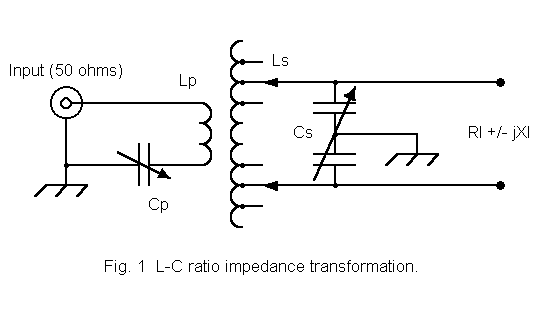
Figure 1 shows a series input capacitor, but for now, let us only use it to cancel out the reactance of the input inductor so that the source has a purely resistive load. The secondary shows a set of coil taps to which the capacitor is connected, so that the result is a tuned circuit of differing L-C ratio as one moves from one tap to another. Since each tap represents a different value of inductance, the inductive reactance also changes accordingly. This requires a new value of capacitive reactance for resonance, and hence a new value of capacitance. Since we are lowering the inductance and the inductive reactance of the secondary, new lower values of the load resistance will be needed to re-establish Q at its former value.
For the exercise, here is a table of values we might derive from this situation, using our initial tuner design as a basic starting point:
           Tuner Component Values for a Constant Q and Varying Loads

            RL (ohms)   XLS=XCS (ohms)    L (micro-H)       C (pF)
            1500        528               12.0               43
            1350        475               10.8               48
             750        265                6.0               86
             300        105                2.4              215

Table 1.  Tuner component values for a constant Q and varying loads.
The table presents us with usable values down to at least a 750-ohms load. Below that point, the required value of capacitance to resonate with the tapped inductor increases to a much more difficult level. If we install a 250 pF capacitor, the rate of change of capacitance grows higher, while if we install only a 100 pF capacitor, the range is insufficient for lower values of RL. This is a limitation of changing the L-C ratio of the secondary tuned circuit, but it is not the catch we mentioned.
The catch is simply this: in order to reduce the value of the secondary inductor reactance, we have to reduce the inductance of the coil. In practice, simply eliminating some turns in the secondary coil will alter the relationship of the primary to the secondary, changing the mutual inductance and hence the coefficient of coupling. Restoring the coefficient of coupling will therefore require some physical alteration of the coil positions.

Although this system of tailoring the inductor reactance to the load resistance for a constant Q is feasible for a single band of operation, it has additional drawbacks when applied to link couplers designed to cover most of the HF bands. First, the number of taps grows well beyond the range of a switching system, and manual tapping becomes necessary. Second, on the higher frequency bands, most of the coil is unused. Since inductors have inter-turn capacity, it is possible for the large unused portion of the coil to have a self-resonant frequency at the operating frequency or a harmonic of it.
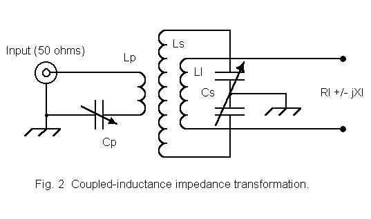
Figure 2 shows one way of effecting the transformation. We simply create a second inductively coupled circuit between the original secondary and the load. We may call this new inductor LL, the load winding. We could even add optional series capacitors, CL, which would provide us with the ability to resonate LL at the operating frequency.
The impedance transformation between LS and LL operates according to the same equations that govern the relationship between LS and LP. Since we are interested here in the ratio of primary to secondary impedance, let's rewrite equation (1) in general primary-secondary terms:

Where the secondary of the coupled load circuit is not resonant, the ratio will vary further due to the presence of a coupled value dependent on XLL, the reactance of the load winding, and an additional reactance will be coupled to the tuned parallel circuit. The reactance is normally compensated for by a revised setting for the variable capacitor.
The circuit of Figure 2 is not often used in amateur work, although it is an efficient way in which to transform lower load resistances to the higher value required by the parallel tuned inductive circuit. The use of a further inductor complicates mechanical arrangements, especially if the arrangements involve switch leads. However, the circuit is applicable to special situations that call for the matching of a single load value with small variations around the target value.
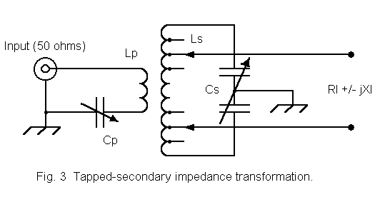
Equivalent to the coupled circuit in figure 3 is the arrangement shown in Figure 3. Instead of a separate winding, we use coil taps on LS to create an autotransformer. Nothing changes relative to the principles of operation that we have just surveyed, except that we lose control over the value of k. However, normal practice is to tap the inductor LS every turn or two, depending upon its construction. The result is the ability to handle a wide range of specific values of RL lower than the value required by the full inductor for a given desired primary impedance.
Although subject to variations by virtue of the value of k (or the mutual inductance) necessary to effect maximum power transfer between windings, the impedance transformation may be crudely estimated by taking the ratio of the squares of the individual inductor values (or the squares of the inductor reactances). In the following representative table, we have further simplified the calculation to one comparing numbers of turns, beginning with a coil of 20 turns. Since the coil is tapped inward one turn from each end with each step, the net reduction is 2 turns per step.
                   Values of RL vs. Approximate Turns Ratios

Number      Ratio to          Ratio Squared     Approximate Ideal RL
of Turns    Full Coil
  20          1.0                   1.00              1500 ohms
  18          0.9                   0.81              1215
  16          0.8                   0.64               960
  14          0.7                   0.49               735
  12          0.6                   0.36               540
  10          0.5                   0.25               375

Table 2.  Values of RL vs. approximate turns ratios.
The values in Table 2 are not be construed as accurate for any particular coil. Their function is to show the trend in values as an inductor is tapped further toward its center. Note that it is possible to obtain a good match with load resistances in the neighborhood of 300 ohms by this method. Indeed, loads as low as 25 to 50 ohms may be accommodated by this arrangement, although when loads are less than about 100 ohms, a series circuit is generally recommended for maximum efficiency and convenience. We shall discuss series secondary circuits in a future installment.
The values of RL which transform to the higher value occur in step-fashion. However, the values of RL between those steps are ordinarily easily accommodated by the variable capacitors in the tuned circuit and in the primary. Therefore, the optional series capacitors in the output circuit, which we noted were optional, are usually not required in order to effect a match.
One operating inconvenience of the tapping arrangement is that the effective Q of the circuit increases as the coil is tapped closer to its center. The lower the load resistance, the higher the Q. The result throws off the values in Table 2, but this is rarely a problem, given the number of available taps and the variable capacitors in the primary and in the tuned circuit. The inconvenience arises from the sharpness of the resultant tuning. The higher the load resistance and the lower the Q, the more easily a single setting of controls and taps may cover an entire amateur band. With lower load resistances, settings may have to be changed several times to cover the same band. For very low load resistances, a series tuned secondary circuit may provide a lower-Q alternative and more convenient operation.
A second inconvenience associated with the tapped-secondary form of the inductive coupler is the need to change taps. On multi-band tuners, the number of available taps can easily outgrow the ability of good RF-rated switches to handle. Manual tapping with band changes is possible, but it is often inconvenient in high speed operations, such as contests. Therefore, the tapped-secondary type inductive coupler is often used mostly for casual operation or for single-band units, such as couplers for 160 meters, where a set of taps may suffice for a given antenna, with only capacitor adjustments required as the operator moves across the band.
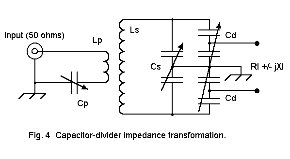
Except for the input-side capacitor, the schematic is similar to the Johnson Match Box design. With the capacitor, it resembles the Annecke link coupler. To see how the capacitor diver system accomplishes the same goal as the tapped inductor, lets break the circuit down into useful chunks. First, we can note that the circuit is balanced around the ground point, so let's work with a single-ended (or unbalanced) circuit. It might make the principles somewhat clearer.
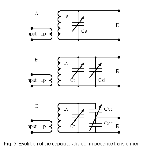
In Figure 5, we take a single-ended tuned circuit through several stages of development. In 5B, we simply divide the tuning capacitor shown in 5A into two paralleled capacitors: CT, which will be the main tuning capacitor, and CD, the "divider" capacitor. Of course, no dividing is yet going on.
In our running example, we needed 43 pF of capacitance. We might have selected a 75 pF capacitor to provide plenty of range on either side of the projected ideal setting. If we divide the capacitor into 2 sections, we might let CT be 65 pF and CD be 12 pF. (We are here working with some convenient hypothetical values that ignore the balanced nature of the full circuit. We shall restore that circuit and more nearly correct values at the end of this exercise.)
In 5C, we replace the simple capacitor CD with a differential capacitor. A differential capacitor is a split stator capacitor with the plates arranged so that as one set meshes, the other set separates. If the plates are cut for straight-line capacitance, the sum of the two capacitances is approximately equal.
However, the two capacitors are arranged in series, so that the net capacitance will range from a very low value (depending on the minimum capacitance of each unit) to a maximum when each unit is meshed 50%. We might select a capacitor with a maximum capacitance per section of 50 pF, which would yield a maximum total capacitance across the unit of 12.5 pF with the plates meshed half way. If the minimum capacitance is 10 pF, then the minimum capacitance for a 10 pF and a 50 pF capacitor in series is a little over 8 pF. The differential would require very little readjustment of the tuning capacitor, CT, across the range of our new CD.
Of greater interest here is the fact that the differential capacitors form a capacitor-divider, with the load resistor connected at the center junction of the differential. Since capacitive reactance is inversely proportional to capacitance, the lower capacitance side of the differential has the greater reactance, and vice versa. The reactances that apply to 5C are XT (total reactance across the differential), XU (upper side reactance), and XL (lower side reactance). since the reactances are in series, XT = XU + XL.
A load of 1500 ohms (our ideal load resistance that couples back to the primary as just about 50 ohms) would require that the XU be minimum and XL be maximum. Since the minimum value of reactance is set by the maximum value of the capacitor section, there may still be some division and the load may appear as a higher value across the tuned circuit than the actual 1500 ohms value.
For load values less than 1500 ohms, the differential is set at an intermediate value such that the load appears across the tuned circuit as close to the ideal value as feasible. As a crude approximation that ignores some of the variables involved in the actual circuit, the load resistances to be matched vary as the ratio of the square of the reactance across the load to ground to square of the total reactance across the capacitor divider. The following table will illustrate the trend.
           Values of RL vs. Approximate Capacitor Reactance Ratios

            CU    XCU   CL    XCL         XT          XCL/XT      RL
                                                             (ideal = 1500 ohms)
            10    2273  50     455        2728        .17           43
            25     909  25     909        1818        .50          375
            40     455  10    2273        2728        .83         1041

Table 2.  Values of RL vs. approximate capacitor reactance ratios.
Once more, the values in the table are not meant to be accurate, but to indicate the trends. Obviously, some circuit adjustments to the secondary L-C ratio would have to be made to handle higher loads, since a load of a little over a thousand ohms appears as 1500 ohms across the tuned circuit. However, it is evident that the capacitor-divider system is capable of handling a very wide range of load resistances with components of limited range.
There is no reason why the sections of the differential capacitor must have the same maximum capacitance. The capacitance per section can be tailored for a desired range of XCL to XT. However, in multi-band tuners, expected perhaps to cover 80 thorugh 10 meters, the component selection will be a compromise. Hence, the range of load resistances that the tuner can accommodate may differ from one part of the spectrum to the another.
In order to restore our circuit to a fully balanced version, as shown in Figure 4, we need to use a split stator tuning capacitor. Since the total capacitance across the series connected capacitor sections is to be about 75 ohms, we need to choose a 150-150 pF unit (although a 100-100 pF unit will provide the basic 43 pF required by the running example). Likewise, for a 12.5 pF total series capacitance maximum for the dual differential unit (when it is set for 50% mesh of both differential units), we shall need a maximum capacitance of about 100 pF per section at full mesh.
One final advantage attaches to the dual differential capacitance divider: tuning is continuous, with none of the stepping required by the tapped inductor. Thus, a precise setting is possible for any load resistance within the divider range. In principle, this ability within the secondary does away with the need for a series variable capacitor in the primary circuit, and the Johnson Match Box indeed omitted this component. However, Annecke has restored it in order to provide the operator with an added measure of flexibility. The flexibility does mean that more than one set of control positions will provide a 1:1 SWR for the input. The best set of control positions is the one providing maximum output to the line, which requires a measurement not usually provided in any ATU.
Although it is possible for any particular case to calculate quite accurate values, doing so would require the specification of all applicable variables. Where those variables can be fully specified, one might adapt the full algebraic procedures spelled out in detail in an old Rider publication called Impedance Matching, one small volume in the "Electronic Technology Series" from the late 1950s (edited by Alexander Schure). The relevant section is called "Transformer as Impedance Matching Device."
For our purposes in this brief tutorial, not only would the full specifications obscure the general principles being presented, they would also be of limited, if any, use in designing a working link-coupled ATU. Because real ATUs operate over a wide range of load resistances and Qs, their actual design is largely a combination of approximation and experimental experience. Later, we shall present some tables of recommended values based on experience, and hopefully, these principles will be evident in their selection.
At the same time, a good link-coupled ATU must also provide maximum flexibility to
achieve a good match and maximum output together. So far, the circuit in Figure 4 comes
closest to that ideal.
Updated 11-28-97. © L. B. Cebik, W4RNL. Data may be used for
personal purposes, but may not be reproduced for publication in print or
any other medium without permission of the author.