
 4. Transmission Lines as Lumped Constants
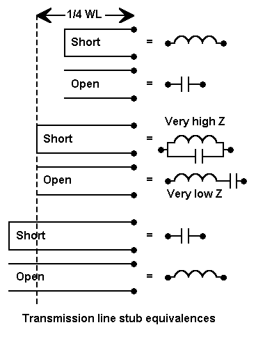
Shorted stubs less than 1/4 wavelength long provide inductive reactance. At exactly 1/4 wavelength long, the stub becomes the equivalent of a very high impedance parallel resonant circuit, creating a virtual open circuit between the terminals. Longer than 1/4 wavelength, the shorted stub becomes a capacitive reactance.
Open stubs follow an opposing path. Shorter than 1/4 wavelength, they provide capacitive reactance. At exactly 1/4 wavelength, they are the equivalent of a very low impedance series resonant circuit, creating a virtual short circuit between the terminals. Longer than 1/4 wavelength, the open stub becomes an inductive reactance.
We can easily calculate the reactance of a length of shorted transmission line if we know the characteristic impedance (Zo)--along with the velocity factor of the line. For shorted stubs, the equation is as follows:
where Zo is the characteristic impedance of the line, X is the reactance, and "beta l" is simply the line length in electrical degrees or radians. Of course, you must precalculate how many electrical degrees or radians there are in the physical length of line with which you start. Likewise, if you turn the equation around to determine the length of line required for a certain reactance, you will have to translate the result from electrical degrees or radians in the units of measure of length you are using.
For open stubs, we use the equation

where the terms have the same meaning. The value of X will be either positive or negative, indicating inductive or capacitive reactance. At exactly 90 degrees, the tangent of the angle climbs without limit, resulting in a value of reactance that is zero for open stubs and that is indefinitely high (some folks like to say infinite) for shorted stubs.
At zero degree lengths and at multiples of 180 degree lengths, the value of the tangent of the angle is zero. The stubs reverse their roles with their 1/4 wavelength counterparts.
There are a number of applications of shorted and open stubs in antennas, and we can model most of them. However, we must always remember that transmission lines (TL entries) in NEC represent lossless lines. For all but short lines, we should externally calculate line losses in the final evaluation of any antenna design where the line or stub is a part of the antenna.
This process is invisible with EZNEC.
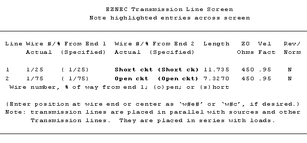
As the screen replica shows, we have inserted 2 stubs in Wire 1. The first is a shorted stub, which we specified simply by keying "s" for end 2 of the transmission line. The remainder of the entry of length, Zo, and velocity factor are normal. We use a similar procedure for the second open stub by specifying "o" for end 2 of the line.
What the entry does not show you is a second wire created by the program to act as the other termination of the line specified. The line is created about 100 wavelengths away from the antenna in all 3 axes, X, Y, and Z. Additionally, the line is about 0.002 wavelengths long and divided into two segments, one to act as the terminal point of each of the two loads. The wire has a radius of about 0.0001 wavelength, the smallest permissible under NEC. Each of these measures ensures that the wire will interact minimally with the other wire segments, thus not disturbing the accuracy of the impedance, current, and field calculations.
You can easily recreate this situation with programs, such as NEC-Win, where you may have to create your own stub conditions.
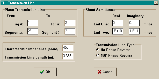
The TL window in NEC-Win presumes that you have created the second wire. In this case, we are creating a shorted stub at wire 1, segment 25, and it goes to wire 2, segment 2. We are using 450-ohm transmission line with a length of 3.687 meters (12.09'). Note, however, one final necessary element of the stub. End 2 must specify the conditions for a short circuit across the terminals, which means an indefinitely high value of "shunt admittance" (the inverse of a shunt impedance). Since the boxes are small, I have move the "real" (conductance) component to the right to show the exponent value, while the "imaginary" (susceptance) component remains shifted left. Values of 1E+10 are so high as to be indistinguishable from a true short circuit.
The corresponding input line in the text editor would appear as follows:
     TL    1     25     2     2    450  3.687  0    0    1E+10 1E+10
        1st End Seg. 2nd End Seg.  Zo  Length Real Imag. Real  Imag.
         Wire #  #    Wire #  #   Ohms meters Adm. Adm.  Adm.  Adm.
                                               W1 shunt    W2 shunt
For an open circuit, we would use the same procedure, but place values of 1E-10 in each of the boxes. This low a value of admittance corresponds to a value of 1E+10 for impedance, indistinguishable from an open circuit. Although such values are manually placed in this NEC-Win example, EZNEC places them automatically and invisibly to the user.
Now that we can create transmission line stubs, we can litter our antennas with them. Unlike physically modeled transmission lines and stubs, these TL entries occupy no wire segments, speeding core calculation runs and allowing greater antenna detailing. They appear in series with loads on the same segments they occupy, but in parallel with sources on the same segment.
Now let's replace the R-X and R-L-C type loads with a transmission line stub. In fact, let's try a couple of different stubs.
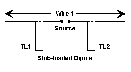
First, we can replace the loads with TL entries at the same segments using 450-ohm, 0.95 VF transmission line. The standard equation tells us that the line needs to be 11.494' (3.503 m). This will show up in the TL line in the text editor as 3.687 m, the equivalent length of line with a VF of 1.0. (The second wire is assumed to have been placed either manually or automatically by the program.)
At our test frequency, the model returns (in NEC-4) a source impedance of 26.09 + j1.72 ohms, and a gain of 1.76 dBi in free space. The slight numerical differences from the R-x and R-L-C load models, of course, make no difference at all.
Now let's replace the 450-ohm line with 50-ohm coaxial cable with a VF of 0.66 (RG-213). The required line length will be 11.05' (3.369 m), which will translate to 5.104 m of 1.0 VF line in the TL entry.
Using this line in the model, it returns a source impedance value of 26.09 + j2.147 ohms and a free space gain of 1.76 dBi. Again, no difference.
Although we recognize that these lines are lossless in the model, losses in transmission line lengths--when used within their recommended limits--tend to be negligible for such short lengths. We would expect no changes in the real antenna that are attributable to line loss adjustments, in contrast to those occasioned by wire and line cutting and assembly precision. However, transmission lines have at least wire losses which given them finite Qs in applications such as these. Although the Qs may be higher than those of inductors, we may not expect true lossless performance.
An exercise such as this one can mislead as well as instruct. At first sight, it would appear that we might easily replace our loading inductor with transmission line stubs and have the same antenna. This would be true if and only if we operated the antenna only at 14.15 MHz.
Source Resistance (in Ohms):
Type Load  FQ: 14.0    14.05  14.1    14.15   14.2    14.25   14.3
Inductive      24.84   22.24  25.66   26.08   26.52   26.96   27.42
450-ohm Stub   24.38   24.92  25.49   26.09   26.70   27.36   28.04
50-ohm Stub    20.25   21.65  23.50   26.09   29.98   36.50   49.50

Source Reactance (in Ohms):
Type Load  FQ: 14.0    14.05  14.1    14.15   14.2    14.25   14.3
Inductive      -42.3   -27.8  -13.1    1.65   16.47   31.77   47.06
450-ohm Stub   -68.9   -46.1  -22.5    1.72   26.59   52.64   79.38
50-ohm Stub    -320.   -240.  -136.    2.15   198.8   502.9   1038.

SWR relative to 26.08 Ohms:
Type Load  FQ: 14.0    14.05  14.1    14.15   14.2    14.25   14.3
Inductive       4.54    2.82   1.65    1.07    1.85    3.12    4.90
450-ohm Stub    9.35    5.07   2.34    1.07    2.65    5.71   10.50
50-ohm Stub    >100.   >100.   32.3    1.08    52.5   >100.   >100.
Clearly, something is different about the stubs relative to the inductor-- and between the stubs themselves. Although the rate of change in source resistance is moderate as we move from one load to the next, the rate of change in the source reactance is much higher for the stubs--and extremely high for the low-impedance transmission line. The 2:1 SWR operating bandwidth for the inductive load is less than 200 kHz, for the 450-ohm stub less than 100 kHz, and for the 50-ohm stub less than 20 kHz.
Stubs change reactance according to changes in the TAN function of the electrical length in degrees or radians and relative to the characteristic impedance of the transmission line. Inductors, however, change reactance according to changes in frequency. The differences in the way each changes reactance do not show up if the required inductive reactance of a shorted stub is low--in the 0 to 100 ohm range.
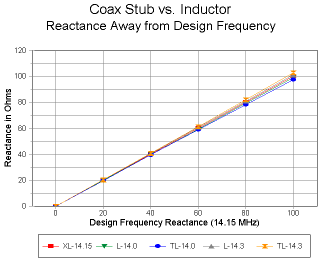
The graph compares change in reactance at 14.0 and at 14.3 MHz for an inductor (inner lines) and 50-ohm transmission stubs (outer lines) when the load at 14.15 MHz is assigned values between 0 and 100 ohms. Even at the upper end of the graph, the differential between 50-ohm stubs and an inductor is a matter of a few ohms. However, when the required inductive reactance is greater--between 100 and 800 ohms--a more radical divergence appears.
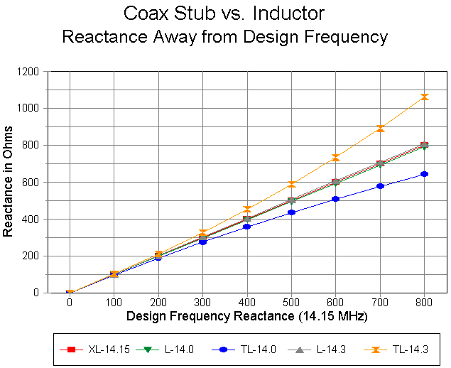
As the graph shows, the inductor changes its reactance by only small amounts all the way up to 800 ohms. However, the 50-ohm transmission line stub changes its value more rapidly as the frequency departs from the design center as the load value increases. The result is that for antennas requiring high values of inductive reactance as loads, the 50-ohm stub permits only a very narrow operating bandwidth.
The 50-ohm stub is a very extreme case, used here to dramatize the differences in the rate of change of value between transmission line stubs and inductors with frequency movement from the design center. Fortunately, the higher the impedance of the transmission line stub, the smaller the difference between its change of reactance and the change of reactance of an inductor over the same frequency deviation from design center.
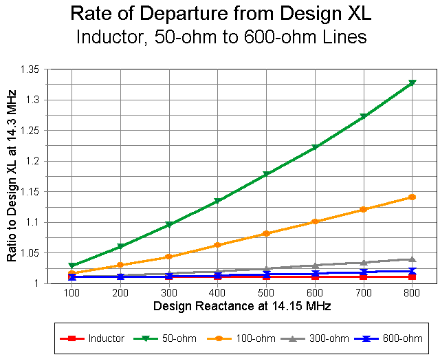
The graph above is developed on a different premise. Let us use the change of reactance of the inductor as a base line. If the design center is 14.15 MHz, then at a frequency of 14.3 MHz, the percent of change in reactance will be constant over the entire range of reactances. In contrast, the percent of change of transmission line stubs will very, increasing with the reactance required, and so too will the ratio of the change in reactance in stubs to the change in inductors.
The graph shows the ratios for 50, 100, 300, and 600 ohm lines, relative to the inductor's baseline. The lesson is clear: for the widest bandwidth when using transmission line stubs, use the highest feasible characteristic-impednace transmission line. Even so, a lossless inductor will always show a wider operating band width than an equally lossless transmission line stub.
For inductors, Qs of 150 to 300 are common in antenna loading service. These Qs generally further increase the operating bandwidth at the cost of slight losses in antenna gain due to the resistive losses. In contrast, transmission line stubs less than 1/4 wavelength long rarely have Qs less than 300, and often they can reach 1000 to 1500. Hence, stubs offer slightly higher gain at the expense of operating bandwidth for any given antenna design that is inductively loaded.
For the antenna modeler, this exercise should reinforce the importance of making frequency sweeps across every the range of frequencies for which the antenna is designed. The sweep must be run using the correctly modeled load for the application. Even if losses are not apparent from the modeling exercise itself, they can be separately calculated and factored into the design.
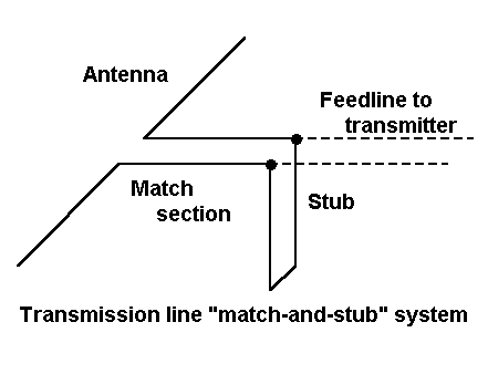
The antenna model consists of one wire, 44.2' (13.48 m) long, with 31 segments. We shall place this antenna at a height of 35' (1 wavelength) above medium ground conditions. The program returns a gain of 10.76 dBi and a source impedance of 135.3 -j680.1 ohms. The source impedance becomes the starting point for our match-and-stub system. We shall use 450-ohm, 0.95 VF parallel line for the transition to our 50-ohm coax.
Because transmission lines are impedance transformers, we can find 2 points along each half-wavelength of the initial 450-ohm line at which a properly sized stub (either open or shorted) will yield an impedance of 50 +/- j0 ohms. (The limiting case is where the impedance along the line never reaches 50 ohms, in which case, we must select a different Zo line for the match and stub system.) We can use either a Smith Chart or a utility program, such as the one included in the HAMCALC collection, to simplify the calculation process.
For the case in hand, we find that lengths of A. 4.983' and B. 5.441' are able to support stubs for the transformation. At point A., a shorted stub 1.176' long or an open stub 9.373' long will do the job. At point B., a shorted stub 12.216' long or an open stub 7.020' long will also do the job.
Ordinarily, we select the combination of matching section and stub that is shortest. In this example, the 4.983' + 1.176' stub combination is the most compact.
To place these lines in the model, we create a second wire, 0.02' long at a height of about 30' up. The exact height is not critical, since we shall control the length of the match line with the TL entry. If we must manually create the distant wire for the termination of the shorted stub, we do so at this time.
Then we enter two transmission lines, both 450 ohms and 0.95 VF. The first goes between wire 1, segment 16 and wire 2, segment 1. The length is 4.983 feet. The second is a shorted stub from wire 2 segment 1, with a length of 1.176 feet. (Adjust lengths for a VF of 1.0 if directly entering values into the TL line: 1.599 m for the match line and 0.378 m for the stub.) Be certain to move the source from the center of wire 1 to wire 2, segment 1.
Running this revised model yields at 28.5 MHz a source impedance of 49.97 - j0.01 ohms, showing the coincidence between the external calculations and our modeling. The gain, of course, does not change. However, once we have established the fact that our external calculations and our modeling work coincide, is there any use to installing the transmission lines in our model?
The answer is affirmative, for we can use this installation to determine the anticipated 2:1 SWR operating bandwidth of the antenna. If we perform a frequency sweep across the first MHz of 10 meters, we obtain the following data:
     Frequency         Source Impedance       50-Ohm SWR
       in MHz            R +/- jX Ohms
     28.0              111.0 - j26.13         2.37
     28.1              93.43 - j22.74         2.02
     28.2              79.03 - j17.74         1.71
     28.3              67.30 - j11.98         1.43
     28.4              57.75 - j 5.97         1.20
     28.5              49.97 - j 0.01         1.00
     28.6              43.57 + j 5.74         1.20
     28.7              38.29 + j11.21         1.45
     28.8              33.89 + j16.36         1.73
     28.9              30.22 + j21.18         2.07
     29.0              27.12 + j25.70         2.47
The data tell us that we are likely to be able to operate the antenna without equipment indisposition over at least 0.8 MHz bandwidth. Moreover, using the curve as a guide, we are likely to be able to make field adjustments of the actual match and stub system to bring it into line with the portion of the band we most wish to use. Since we are using a mere 6' (2 m) of line for the match and stub system, line losses will be negligible within it. In any event, the losses will be far less than had we designed an inductor at the feedpoint to compensate for the capacitive reactance, followed by a 2:1 transformer to bring the resistive component of the source impedance closer to 50 ohms.
This example, I hope, illustrates the utility of judiciously employing stubs in antenna models beyond their function to load antenna wires. I recommend that you rebuild the model using each of the other three combinations of match line and stub just for the practice in using TL entries in models (if not out of curiosity over whether those values "work").
In addition, we must always be aware of basic NEC limitations. Primary among these limits is the possible unreliability of results where wires of different radii (diameters) meet, especially at angular junctions. If possible, one should model such geometries using the same wire size throughout, and this may require the development of several different models to obtain all of the desired output data, such as element lengths, stub lengths, gain, and source impedance. In addition, segments at and near angular junctions should be consistent in length and short.
Let's sample the process by replacing the loads and transmission lines in the half-length dipole with physically modeled transmission line stubs. To do this, we must restructure the entire model. Instead of one wire, we shall need 9, in accord with the upper diagram of the following figure.
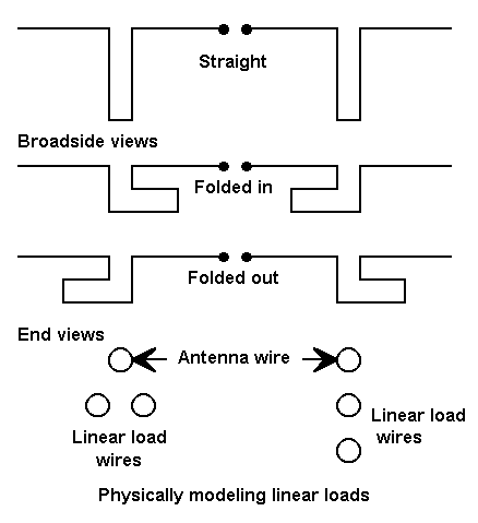
The wires follow the following table:
Wire  Conn.  End 1 (x,y,z : in)     Conn.  End 2 (x,y,z : in)

1          -101.21,  0.000,  0.000  W2E1 -54.000,  0.000,  0.000
2     W1E2 -54.000,  0.000,  0.000  W3E1 -54.000,  0.000, 76.300
3     W2E2 -54.000,  0.000, 76.300  W4E1 -50.000,  0.000, 76.300
4     W3E2 -50.000,  0.000, 76.300  W5E1 -50.000,  0.000,  0.000
5     W4E2 -50.000,  0.000,  0.000  W6E1  50.000,  0.000,  0.000
6     W5E2  50.000,  0.000,  0.000  W7E1  50.000,  0.000, 76.300
7     W6E2  50.000,  0.000, 76.300  W8E1  54.000,  0.000, 76.300
8     W7E2  54.000,  0.000, 76.300  W9E1  54.000,  0.000,  0.000
9     W8E2  54.000,  0.000,  0.000       101.210,  0.000,  0.000
The source is at the center of wire 5. Dimensions have been translated into inches for ease of seeing the modeled structure. The stubs are composed of the same #14 copper wire as the antenna element and are 4" wide by 76.3" long. The stubs are centered at the approximate points where the loads and transmissions lines had been assigned in previous models.
The model returns a gain of 1.47 dBi and a source impedance of 18.02 - j0.55 ohms. The gain figure is less than the 1.76 dBi returned by the earlier models. However, remember that the stub now accounts for wire resistance losses. In fact, if we add a resistance of 0.93 ohms to the reactive load of 870.4 ohms in previous models, we find that the R-X model returns the same gain figure of 1.47 dBi. 0.93 ohms resistance in series with a reactance of 870.4 ohms represents a Q of about 936, well higher than what we can achieve with real inductors.
The model is also instructive with respect to the length of the stub, which is considerably shorter than what a standard calculation of a shorted stub would yield. #14 wire with 4 inch spacing has an approximate Zo of 580 ohms, which would call for a length of about 130" for the stub. The actual stub is 76.3" long. However, the theoretical stub presumes equal but opposite currents in each leg. Examining the current table returned for this model will show the currents for any given position across the stub lines to be significantly different.
(Note: Modelers should be very cautious at this point with respect to the accuracy of the stub length as modeled in NEC-2 or NEC-4. Even 4" apart at 14.15 MHz, the stub wires are very close. NEC may become inaccurate with very closely spaced wires, even when the modeler has observed all cautions regarding using the same wire diameter at angular junctions and regarding the alignment of segments in the parallel wires. This same antenna was modeled in MININEC 3.13 (which has limitations of its own, but not in this area) via ELNEC, and the requisite stub lengths were 1.3 to 1.6 inches longer, depending upon the precise technique used to construct the model. Since the stub length differential approaches 2%, the variance must be considered significant.)
Stubs close to the feed point, where the current changes slowly as one moves along the antenna wire, will model physically in close accord with standard parallel transmission line calculations. However, for closest equality of current magnitude on the wires, they must be positioned symmetrically relative to the antenna wire, as shown in the lower left of the figure. If they are positioned linearly, the currents will be unequal due to the unequal distances from the main antenna element. Likewise, stubs positioned further out along the antenna wire, even if positioned symmetrically relative to the antenna wire, will show considerable differences of current on the two parallel wires. At a certain indefinite point along the wire, stubs act less like transmission line sections and more like simple wire extensions necessary to lengthen an antenna element to resonance.
The differences in currents along the two stub wires tend to be somewhat less if the stub wires are folded back or folded outward, parallel to the antenna wire and equally spaced from it. When positioned straight down, the unequal currents in the stubs yield a small vertically polarized field that in one plane is down from the main lobe by only -18 dB. It is largely the interaction of this field with the main element field that reduces the source impedance to 18 ohms from the 26 ohms found in the other models.
A physical model of the stub-loaded half-length dipole also provides an interesting lesson in operating band width. Relative to the resonant source impedance of 18 ohms, the SWR at 14.0 MHz is 2.50 and at 14.3 MHz is 2.30, well below the modeled figures for lossless transmission lines and lossless inductors. However, the physical model includes its losses, which increase the operating bandwidth.
The point of generating this sample physical model of transmission line
stubs--usually called "linear loads" among antenna designers--is to
illustrate some, but by no means all, of the differences between using
lossless and non-interacting mathematical antenna parts and physical lossy
and fully interactive antenna parts. Each provide valuable information
about anticipated antenna performance and each withholds valuable
information. Physical modeling is limited by certain program limitations
that force the modeler to depend in part on the use of mathematical
substitutes. However, only by thorough modeling in both modes can one
develop a good sense for what to expect by way of field adjustment in real
antennas.
Updated 1-3-98. © L. B. Cebik, W4RNL. Data may be used for
personal purposes, but may not be reproduced for publication in print or
any other medium without permission of the author.