
 The Monoband Log-Cell Yagi Revisited
Although the design had been known earlier, the monoband log-cell Yagi array was briefly popular in amateur literature in the late 1970s and early 1980s, largely through the work of Rhodes, K4EWG, Painter, W4BBP, and Zimmer, K4JZB.1 Versions can be found in Orr and Cowan's Beam Antenna Handbook, and in the ARRL Antenna Book. In recent times, interest in the design has renewed.
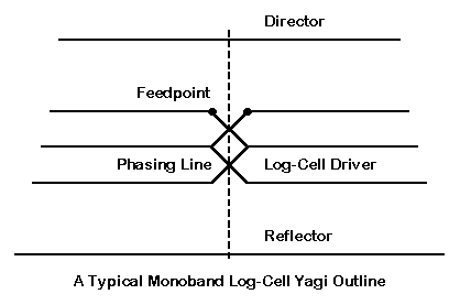
Fig. 1 shows the outline of a typical monoband log-cell Yagi. It consists of a log-cell driver consisting of 2 or more elements driven with a phasing line that reverses as it connects each element. The element set is fed at the forward-most position, much like a log-periodic dipole array (LPDA). To the driver cell are added a reflector (usually) and one or more directors.
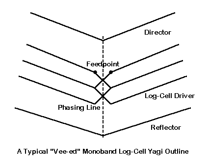
In Fig. 2, we see a common variant of the basic log-cell Yagi. In this case, favored especially by K4JZB, the elements are bent forward by about 40 degrees from linear each side of center.
Since most of the articles on the log-cell Yagi appear before the advent of computer antenna modeling via MININEC and NEC, the claims for their performance are highly optimistic. One source reports a 6 element log-cell Yagi to have a gain of 16 dB, but it conveniently gives no reference standard. Most sources report gain to be greater than for Yagis of equivalent boom length, but these reports compare the log-cell Yagi with antennas deeveloped before computerized optimization of the Yagi design became commonplace. Perhaps only Rhodes and Painter stress operating bandwidth as a major advantage of the antenna design.
With the renewed interest in the antenna, many potential users read the older claims as if they would stand up to modern scrutiny. However, to date, I have seen no re-evaluation of the log-cell Yagi design. Modern analytical tools, such as computer modeling, offer us a chance to better understand the antenna and to assess its place among monoband antennas used by amateurs.
The purpose of this series is to contribute a little toward the re-evaluation of the log-cell Yagi, using NEC-4 as a means of analyzing various aspects of the design. Throughout, I shall uses 10-meters as a focal point, since this band is the widest of the upper HF amateur bands. In this introduction, I shall look briefly at a superior log-cell Yagi design, and then look at the performance characteristics of some pure Yagi designs that we might use as standards of comparison. In this way, we can begin to see more clearly where the log-cell Yagi fits into the amateur arsenal of antennas.
In Part 2, we shall examine some basic principles behind the log cell itself, with especial attention to element phasing. One might also use LPDA principles to show how a log-cell works, but the basics of element phasing can make a number of facets of both Yagi and log-cell Yagi design somewhat clearer.
In Part 3, we shall look at several (at least 4) practical 10-meter log-cell Yagi designs. I shall claim no great originality for any of the designs, although each has required considerable effort to optimize all of the operating characteristics, including gain, front-to-back ratio, and SWR bandwidth. All of the antenna designs will feature direct 50-Ohm feedpoint impedances.
In the final section, Part 4, we shall examine the V-element question. Does bending half-wavelength elements forward contribute anything useful to the performance of the log-cell Yagi? This question, of course, will involve us in a broader question of V-ing any half-wavelength element.
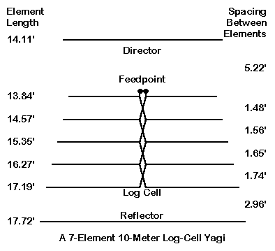
The basic dimensions of the refined model appear in Fig. 3. The material for the model is 1" diameter aluminum, although similar performance can be achieved with elements as small as 0.5" in diameter.
The log-cell is designed as a true LPDA, with elements tapering in length and spacing as one moves forward toward the feedpoint. As one might expect, the reflector is the longest element of the entire set. However, the director is longer than the forward-most element of the log cell. Directors for log-cell Yagis must be cut for the operating frequency, while the forward element of the log cell will be resonant well above the highest operating frequency. The overall length of the antenna is about 14.6' or so, which would fit the antenna easily on a 15' boom.
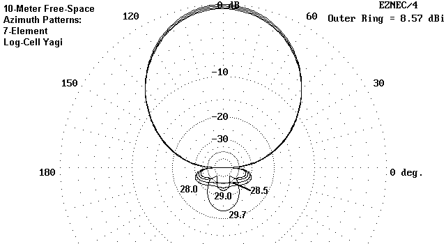
Fig. 4 provides a snapshot of antenna performance across all of 10 meters from 28.0 to 29.7 MHz. The highest free-space gain is at the upper end of the band, with the free- space gain at 28 MHz being just above 8 dBi. The first MHz of the band also shows a very high and stable front-to-back ratio of 30 dB or more, with the figure at 28.5 MHz exceeding 40 dB. The 50-Ohm SWR of this antenna remains well below 2:1 across the entire 10-meter band.
Actually building this antenna would require element length adjustment if an element diameter tapering schedule is used. However, nothing in the design would require special construction except perhaps the 100-Ohm phasing line for the log cell. We shall return to this and other practical designs later in the series. First, let's consider whether the antenna is worth building. For that evaluation, we need some standards of comparison.
Because the most common comparator for a log-cell Yagi is a pure monoband Yagi, perhaps it may be useful to examine some of the operating characteristics of several good Yagi designs. Let's begin with designs I refer to as medium-bandwidth arrays, because they hold their operating characteristics from 28 MHz up to 29 MHz--or close to it. We shall look at three designs in particular.
First is a 3-element Yagi on an 8' boom (3-8). The actual overall length of the antenna is about 7.5'. The design is adapted from one of Dean Straw's (N6BV) design in the collection of antennas accompanying the program YA.3 Table 1 provides the modeled dimensions for this and the other two antennas in the medium bandwidth group.
               Medium-Bandwidth 3- and 4-Element 10-Meter Yagi Dimensions

1.  3-Element, Short-Boom (< 8') yagi:  0.5" diameter aluminum elements
Element             Length (")          distance from reflector (")
Reflector            211.9                     ------
Driver               193.8                      36.0
Director             184.9                      90.0

2.  3-Element, Long-Boom (<12') yagi:  0.5" diameter aluminum elements
Element             Length (")          distance from reflector (")
Reflector            206.3                     ------
Driver               197.0                      62.4
Director             185.3                     134.5

3.  4-Element, 13'-Boom Yagi:  0.5" diameter aluminum elements
element             length (")          Distance from Reflector (")
reflector            207.5                     ------
driver               195.9                      35.8
director 1           194.4                      65.5
director 2           182.2                     152.2

Table 1:  Dimensions of medium-bandwidth yagis used as standards of comparison
The second design is adapted from Brian Beezley's (K6STI) design in the samples accompanying AO.4 This longer-boom design (3-12) is actually about 11.2' long and fits easily on a 12' boom. The third design (4-13), again adapted from an N6BV design, uses 4 elements in under 12.7' of length for an easy fit in a 13' boom.
For this exercise, all designs use uniform diameter elements. All are modeled on NEC-4 in free space for the purposes of direct comparison.5 The driven elements of the 3-element beams have been resonated so that SWR figures can be taken relative to the resonant impedance. Because the 4-element beam had a somewhat lower impedance, it has been equipped with a beta match, that is, a shorted transmission-line stub to effect a match compatible with 50-ê coax. The 3-element beams can be matched with a quarter-wavelength matching section, or their drivers can be shortened for use with a beta match.
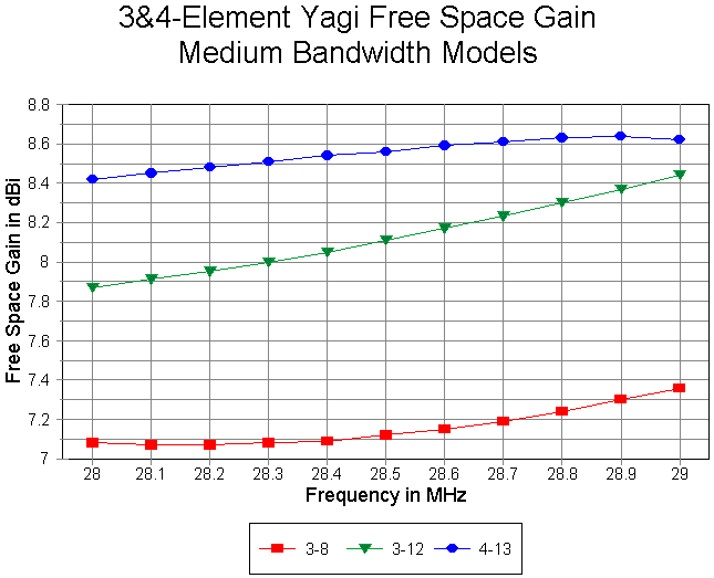
Fig. 5 provides a sweep of the free-space gain of each beam design from 28.0 to 29.0 MHz. As one might expect, the 3-element, 8' boom model shows the lowest gain--just above 7 dBI. However, the gain is fairly constant across the selected portion of the band.
The long-boom 3-element Yagi shows considerably higher gain, averaging nearly a full dB above the short-boom model. Because the boom length is close to the limit of stable operation for a considerable bandwidth, the curve shows greater changes with increasing frequency.
In contrast, the 4-element Yagi shows only slightly higher gain than the 3-element long-boom model. However, the boom length is only about a foot greater than the long-boom 3-element Yagi. What the fourth element provides is more even gain across the selected bandwidth.
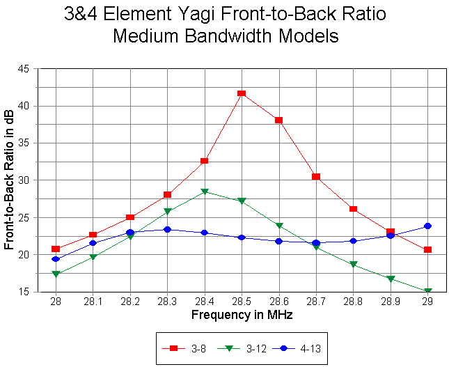
In Fig. 6, we get a picture of the 180-degree front-to-back ratio of the antennas. Interestingly, the short-boom 3-element Yagi shows the highest peak front-to-back ratio and the highest average front-to-back ratio across the band, never falling below 20 dB. Comparatively, the long-boom 3-element Yagi shows a good peak front-to-back ratio, but the value falls below 20 dB between 28.7 and 28.8 MHz. The 4-element Yagi shows a much lower value of peak front-to-back ratio, but the overall curve is smooth and falls below 20 dB only at the lower edge of the band.
From these two parameters alone, we can obtain an impression of the designs. The short-boom 3-element and the 4-element designs are conservative. However, the long-boom 3-element design is pressing the limits of what is possible for that number of elements and boom length. One might obtain even higher gain, but at the expense of an even narrower bandwidth for the operating characteristics.
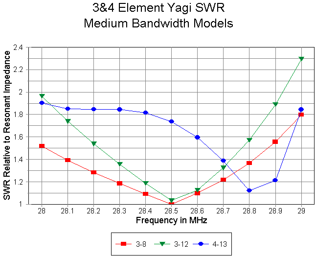
The impression is further deepened in the SWR curves in Fig. 7. The long-boom model shows under 2:1 SWR relative to the resonant impedance through 28.9 MHz. The short-boom 3-element Yagi easily achieves a 2:1 SWR bandwidth relative to the resonant impedance that is wider than the selected band portion. Despite the slight narrowing of the long-boom SWR bandwidth, the use of a beta match would likely permit a wider operating bandwidth at the 50-Ohm matched value. This is illustrated by the 4-element Yagi 50-Ohm bandwidth, which shows under 2:1 SWR across the band. The native bandwidth relative to the antenna's resonant impedance would be about 800 kHz. (However, there may be slight losses associated with operating a beta match well off its optimal values, despite the resulting good impedance match.)
These three antennas are good designs of their types, despite the limitations of each. However, they are not adequate to cover the entirety of 10-meters. For that, we must turn to wide-band designs. The dimensions of two wide-band Yagi designs appear in Table 2.
               Wide-Bandwidth 3- and 4-Element 10-Meter Yagi Dimensions

1.  3-Element, Long-Boom (<12') yagi:  1.0" diameter aluminum elements
Element             Length (")          distance from reflector (")
Reflector            214.0                     ------
Driver               195.6                      74.5
Director             176.0                     134.5

2.  4-Element, Short-Boom (8') Yagi:  0.5" diameter aluminum elements
element             length (")          Distance from Reflector (")
reflector            212.0                     ------
driver               205.0                      40.5
slaved driver        189.0                      44.0
director             181.0                      96.0

table 2:  dimensions of wide-bandwidth yagis used as standards of comparison
One design is a 3-element Yagi. This version was developed by Joe Reisert, W1JR, and is similar to a design published by Bill Orr, W6SAI, in Ham Radio many years ago.6 The boom would be 12' long to hold an antenna whose inherent length is about 11.2' or so. The other design is my own, which fits on a 8' boom and uses 4 elements. The extra element is a second driver open-sleeve coupled to the first such that the two together cover all of 10-meters.
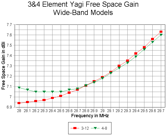
As shown in Fig. 8, the gain curves of the two antennas are very similar, with the 4-element model having a slight edge at the lower end of the band, a function of the dual driver system. It is notable that in a 3-element design, wide-banding the gain requires a boom length similar to that of the higher-gain medium-bandwidth long-boom model--about 12'.
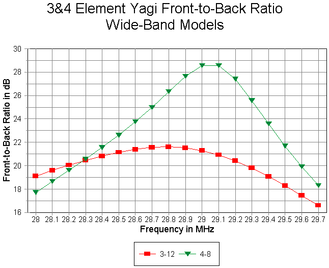
The front-to-back curves in Fig. 9 once more do not give one design a major edge over the other. The dip in value below 20 dB occurs at opposite ends of the band for the two designs--but might be made more coincident with slight redesign of element lengths and spacings. The 4-element model shows a very high front-to-back ratio peak around 29 MHz, where all 4 elements show the highest activity in terms of current magnitude.
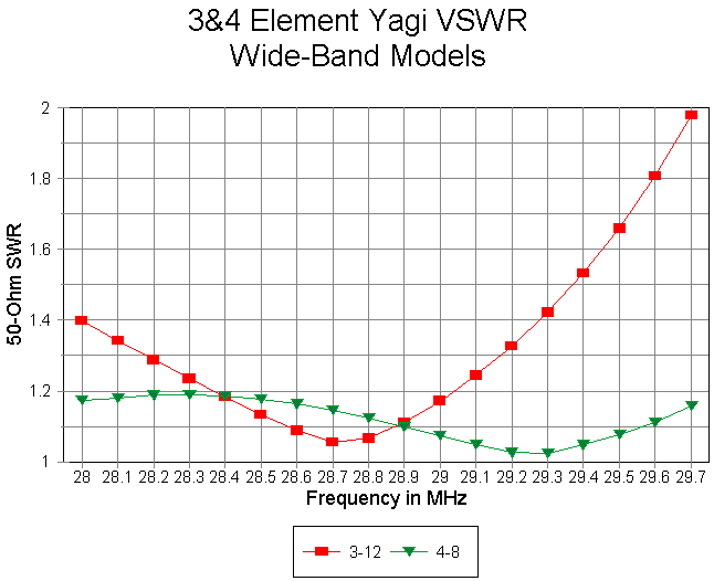
The SWR curves for both wide-band antennas in Fig. 10 are referenced to 50 Ohm without need for a matching system. The 3-element antenna easily achieves a 2:1 operating bandwidth that covers the entire band. The open-sleeve coupled drivers of the 4-element model allow superior performance in this department, with an SWR that never rises to 1.2:1 across the entire band.
In front-to-back ratio, the log-cell Yagi is superior to all of the standard designs, with better than 30 dB until well past 29 MHz and better than 22 dB across all of the band. One of the areas in which well-designed log-cell Yagis excel is in front-to-back ratio. The log-cell Yagi also has a 50-Ohm SWR well under 2:1 across the entirety of the 10-meter band, matching both wide-band Yagis in that performance category.
For a given boom length, then, a log-cell Yagi does not make its claim to fame at the end of the 20th century in the gain department. Advances in pure monoband Yagi design give the edge to the pure Yagi. What may have been true of 1980 Yagi designs is no longer true today.
However, well-designed log-cell Yagis can achieve very wide operating bandwidths, not only with respect to SWR, but as well with respect to operating characteristics. In particular, the log-cell Yagi has the potential for very smooth front-to-back ratio curves at very high levels across a band as wide as 10 meters.
There is, of course, a cost involved in achieving these goals: extra elements and their associated weight. In addition, the log cell requires careful design with considerable attention to the phasing line that interconnects the phased driven elements. To the subject of element phasing we shall turn in Part 2.
1. For information on various log-cell Yagi designs see the following items on this incomplete literature list:
P. D. Rhodes, K4EWG, and J. R. Painter, W4BBP, "The Log-Yagi Array," QST, Dec, 1976. The main elements of this article are reprinted in The ARRL Antenna Book, 18th Ed., pp. 10-25 to 10-27.
Robert F. Zimmer, K4JZB, "Development and Construction of 'V' Beam Antennas," CQ, Aug., 1983, pp. 28-32; and "Three Experimental Antennas for 15 Meters," CQ, Jan., 1983, pp. 44-45.
W. I. Orr, W6SAI, and S. D. Cowan, W2LX, Beam Antenna Handbook, pp. 251-253. John J. Meyer, N5JM, "A Simple Log-Yag Array for 50 MHz," Antenna Compendium, Vol. 1, pp 62-63.
Reference to log-cell Yagis is also made by L. A. Moxon, HF Antennas for All Locations, 2nd Ed., pp. 199-200, but the design shown is the Rhodes-Painter version in The ARRL Antenna Book.
2. James L. Lawson, W2PV, Yagi Antenna Design (ARRL, 1986).
3. YA is a Yagi Analysis program developed by Brian Beezley, K6STI, and accompanies recent editions of The ARRL Antenna Book.
4. AO is a MININEC analysis and antenna optimizer program by K6STI that is no longer available.
5. Two commercial implementations of NEC-4 are available: EZNEC Pro by Roy Lewallen, W7EL, P.O. Box 6658, Beaverton, OR 97007; and GNEC by Nittany Scientific, Airline Highway, Suite 361, Hollister, CA 95023-5621. Use of NEC-4 requires licensure from the University of California. Fortunately, most of the analysis in this series can be replicated using more easily obtained versions of NEC-2.
6. Joe, Reisert, W1JR, "Yagi/Uda Antenna Design: Part 1: A Different Approach," Communications Quarterly, Winter, 1998, pp. 49-59. Orr's version of the antenna appeared in his regular column for Ham Radio, May, 1990.
Updated 1-15-2000. © L. B. Cebik, W4RNL. A version of this item appeared
in The National Contest Journal, Jan-Feb, 2000, 19-22. Data may be used for
personal purposes, but may not be reproduced for publication in print or
any other medium without permission of the author.