
 A 10-Meter LPDA
1. Specifications: since the overall project goal was to see if 3-element short-boom Yagi performance could be extended across the entire 10-meter band with an LPDA, I set the following specifications:
These specifications are apt to the project goal, but not necessarily to some set of specific operator needs for such an antenna. The specs presume equal interest in all parts of the band, which would be a rare phenomena. For just the CW end of the 10-meter band, for example, a 2-element driver- director Yagi would come close to meeting the specifications other than frequency coverage. However, the original questions driving this design and exploration exercise are "Can it all be done, and can a monoband LPDA do it all?"
2. Candidates: Phase 1 eliminated almost all of the common types of antenna used at 10 meters, mostly for want of a wide-band enough combination of performance and SWR coverage. In the course of developing an LPDA design, some other variants were checked and abandoned. For example, the Log-Yagi combination never seemed to approach either of the final candidates in performance across the band. Note, however, that my inability to find the right combination to make the Log-Yagi do the job does not mean that it cannot do the job in principle. It only means that I did not uncover a combination of element length and spacing to make the Log-Yagi work in this context.
The final candidates are represented by models of 3-element and 4-element LPDAs. Since some slight variations of the version presented earlier have emerged since the preceding phases of work were closed (but not necessarily completed), I shall present the models as EZNEC descriptions.
a. 3-element LPDA
LPDA3          Frequency = 28-30  MHz.
Wire Loss: Aluminum -- Resistivity = 4E-08 ohm-m, Rel. Perm. = 1
              --------------- WIRES ---------------
Wire Conn.---End 1 (x,y,z : in)  Conn.---End 2 (x,y,z : in)   Dia(in) Segs
1         0.000,-106.00,  0.000         0.000,106.000,  0.000 3.75E-01  43
2        50.559,-95.300,  0.000        50.559, 95.300,  0.000 3.75E-01  41
3        95.339,-86.000,  0.000        95.339, 86.000,  0.000 3.75E-01  39
              -------------- SOURCES --------------
Source    Wire      Wire #/Pct From End 1    Ampl.(V, A)  Phase(Deg.)  Type
          Seg.     Actual      (Specified)
1          20     3 / 50.00   (  3 / 50.00)      1.000       0.000       I
No loads specified
                -------- TRANSMISSION LINES ---------
Line  Wire #/% From End 1   Wire #/% From End 1    Length     Z0   Vel Rev/
      Actual  (Specified)   Actual  (Specified)              Ohms Fact Norm
1    1/50.0  (  1/50.0)    2/50.0  (  2/50.0)  Actual dist   50.0  1.00  R
2    2/50.0  (  2/50.0)    3/50.0  (  3/50.0)  Actual dist   50.0  1.00  R
3    1/50.0  (  1/50.0)  Short ckt (Short ck)    2.200 in   450.0  1.00
4    3/50.0  (  3/50.0)  Short ckt (Short ck)    7.000 in   450.0  1.00
Ground type is Free Space
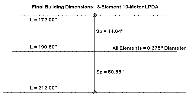
The figure summarizes the element length and spacing data from the model description. This model, now called LPDA3, is essentially the same as the modified N7CL model reviewed in Phase 4. For convenience, 2 small changes have been made, and both involve the modeling of the antenna transmission line and beta match stubs. In this model, the stubs are composed of 450- Ohm parallel line. Actually, any type of line will do. The required antenna transmission line stub reactance is 15.3 Ohms at 29 MHz, while the beta match required reactance is 48.8 Ohms at 29 MHz. Any stub arrangement providing these values of inductive reactance will work as well as any other within the limits of physical feasibility.
b. 4-element LPDA
LPDA4               Frequency = 28-30  MHz.
Wire Loss: Aluminum -- Resistivity = 4E-08 ohm-m, Rel. Perm. = 1
              --------------- WIRES ---------------
Wire Conn.---End 1 (x,y,z : in)  Conn.---End 2 (x,y,z : in)   Dia(in) Segs
1         0.000,-108.50,  0.000         0.000,108.500,  0.000 5.00E-01  43
2        35.605,-98.003,  0.000        35.605, 98.003,  0.000 5.00E-01  41
3        67.475,-87.720,  0.000        67.475, 87.720,  0.000 5.00E-01  39
4        96.000,-78.515,  0.000        96.000, 78.515,  0.000 5.00E-01  37
              -------------- SOURCES --------------
Source    Wire      Wire #/Pct From End 1    Ampl.(V, A)  Phase(Deg.)  Type
          Seg.     Actual      (Specified)
1          19     4 / 50.00   (  4 / 50.00)      1.000       0.000       I
No loads specified
                -------- TRANSMISSION LINES ---------
Line  Wire #/% From End 1   Wire #/% From End 1    Length     Z0   Vel Rev/
      Actual  (Specified)   Actual  (Specified)              Ohms Fact Norm
1    1/50.0  (  1/50.0)    2/50.0  (  2/50.0)  Actual dist   75.0  1.00  R
2    2/50.0  (  2/50.0)    3/50.0  (  3/50.0)  Actual dist   75.0  1.00  R
3    3/50.0  (  3/50.0)    4/50.0  (  4/50.0)  Actual dist   75.0  1.00  R
Ground type is Free Space
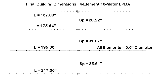
The sketch provides a summary of element length, diameter, and spacing information from the chart. With the 4-element model, elements have undergone a final tweaking, and the 0.5" model was selected as the best compromise between the higher performance offered by the same antenna with very large elements and the desire to hold weight as low as practicable.
3. The Final (?) Decision: selecting the final candidate essentially boiled down to forcing myself to adhere rigidly to my initial specifications, even if one of the candidates offered some advantages in terms of weight.
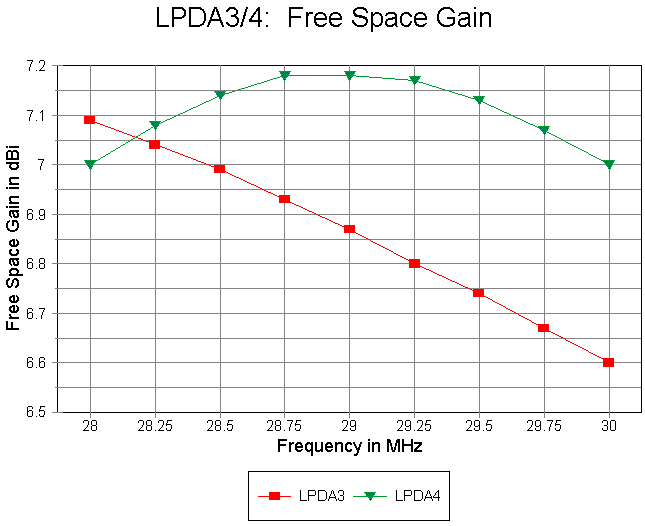
The gain curves show that only the 4-element LPDA meets the gain specification originally set. The 3-element LPDA is a fine antenna for those with more intense interests in the low end of the band and more casual interests in the upper portion. Indeed, where the 8' boom length limit is not a requirement, the N7CL model is to be recommended as providing smoother operation and somewhat more forgiving construction.
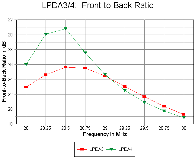
The front-to-back graph reveals the 3-element LPDA to have a smoother curve. Nevertheless, the curve for the 4-element version shows that it meets the front-to-back specification, with the ratio passing through 20 dB at almost precisely 29.7 MHz. Whether this can be preserved in a physical version of this modeled beam is another matter.


The pair of SWR curves show that both beams would meet the 50-Ohm SWR specification. However, the 4-element version has the shallower curve, which promises a bit more room for the normal prototype construction variables.
In addition to the performance specifications, one also should note the methods by which performance is obtained. The 3-element version requires carefully cut antenna transmission line and beta matching stubs (or coils). Both techniques are well-documented and implementation would be straightforward. However, they do add further variables to the design and construction mix. In contrast, the 4-element model can be fed directly (with a feedline choke) and requires no stub at the other end of the antenna transmission line. Since these items were not included in the original specifications, selection of one or the other method would be largely a matter of preference.
In the end, I have decided to pursue the 4-element monoband LPDA, because it promises, by virtue of the design model, to meet all of the original specifications.
4. Construction Planning: in the preceding phase, I looked into several options for constructing the antenna transmission line. Because it offers more flexibility in revising the prototype easily, L-stock lines seem to be the best option. This choice of basic construction methods entails a number of other considerations, ranging from weight to nuts and bolts.
a. Weight: My initial list of weight increments included the following estimates:
1. Boom: an 8' 1.25" boom of standard 0.58" wall thickness stock weighs about 0.26 pounds per foot, or about 2.1 pounds. However, the boom will require judicious reinforcement at least at the boom-to-mast point and possibly where the elements join the boom on insulated plates. Using internal 1.125" diameter stock might yield anywhere from 1 to 8 feet of additional boom weight. For initial estimates, I used 4' or 0.9 pounds, at about 0.23 pounds per foot, for an anticipated total boom weight of about 3 pounds.
2. Antenna transmission line: the L-stock eventually used might range from 0.5" per side to 1" per side. The middle size (0.75" per side) weights about 0.1 pounds per foot, for 0.8 pounds per 8' length. Since we need 2 lengths, we can add 1.6 pounds to the boom weight.
3. Boom-to-mast mounting: my initial plans are to use an unusual mounting system composed of Schedule 40 PVC pieces in order to keep the antenna transmission line well-spaced from the mast. The necessary parts weigh about 0.5 pounds
4. Elements: the 4 elements require a total of a little over 62' of 0.5" diameter aluminum tubing. At nearly 0.1 pound per foot, the elements weigh in at about 6 pounds total. However, initial construction ideas also call for element stiffening with 0.375" tubing, requiring about 16' total of the material. At about 0.05 pounds per foot, we can add 0.8 pounds, for a total element weight of 6.8 pounds. Element plates will likely weight about 4 to 6 ounces each or another 1.5 pounds, for a total of 8.3 pounds.
5. Support hardware and pieces: the antenna transmission line support pieces, coax connector, and the stainless steel hardware necessary to connect and secure the various parts of this prototype will likely add another pound to the total weight.
The total projected weight of the prototype is about 14.5 pounds. A 3- element version of the LPDA would weight about 2.1 pounds less. A production antenna might weight considerably less (perhaps 10 pounds), but the prototype has to be rugged enough to withstand the typical abuse involved in testing, rebuilding, and readjusting. I find it interesting to compare my projections with the weight of the final working unit. Experience has divided my antennas into 3 equal groups: those that weighed significantly less, those that weighed about as projected, and those that weight considerably more. Hence, I have no experiential "fudge factor" to throw into the mix.
b. The antenna transmission line: before adding any elements to the antenna, I want to experiment with various types of hardware depot L-stock, ranging from 0.5" per side to 1" per side (all .0625" thick) for the line.
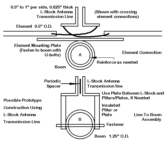
The general scheme shown in the sketch will support the lines. However, it will require revision to suit the actual line used. 0.5" L-stock will fit between the support pillars and require a cross piece. 1" stock might use screws that pass through the stock flange into a threaded tap in the pillar. The exact length of the pillars may also require some testing to see how close the lines can be to the boom before interaction is harmful.
I know of no figures or equations exactly applicable to L-stock in the proposed configuration. Hence, determining when the line has a characteristic impedance of about 75 Ohms will be experimental, although straightforward. For 80-Ohm lines of square stock, the calculated separations from facing surfaces are 0.23" for 0.5" material, 0.34" for 0.75" material, and 0.45" for 1" stock. Another 5 Ohms decrease in Zo, along with somewhat different requirements for L-stock relative to square stock, still holds the potential for a light-weight half-inch L-stock line. Whether this line, if feasible, is also convenient for element and pillar attachment, only testing will tell.
c. Insulated plates: the elements require insulated plates for isolation from the boom. For half-inch diameter elements, plates that are 2" wide by about 12" long (side-to-side relative to the boom) should suffice. 3/8" spar varnished plywood will do in a pinch, but Lexan or some other sturdy structural plastic would be better. U-bolts are the standard fasteners for plate-to-boom and plate-to-element mounting. However, for this light structure, equally light hardware is desirable.
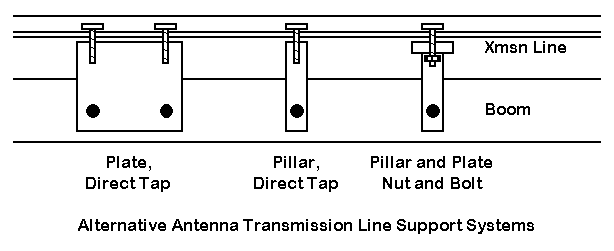
The line support pillars can be true pillars or plates through-fastened to the boom. Since their exact positions are non-critical, drilling the boom is a satisfactory option for mounting. The top assembly will be determined by transmission line construction experiments. Quarter-inch plexiglass or better will serve for the side pillars/plates and allow tapping for either direct fastening of the line stock or of a top plate to support the line.
d. Boom-to-mast mount: proper testing of a prototype suggests strongly that possibly disturbing influences on the antenna structure be minimized. A standard plate for side-mounting the boom to the mast would require spacers to keep the mast from touching or coming in very close proximity to the line. Although this close approach might not affect the line, initial testing can be done with a more isolated mounting system.
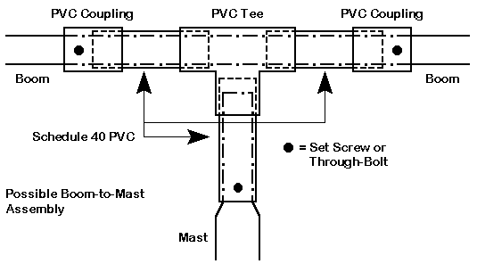
Using Schedule 40 PVC pieces cemented together, one can use the system sketch above to provide an isolated boom to mast mount. Once the center of gravity of the antenna array is determined, set screws can be replaced by bolts passing through both the PVC and the boom. (The mast will be equipped with a shorting strap to the boom to test the effects of grounding the boom or leaving it floating.) Because the 4-element version of the monoband LPDA has no center element, the system has adequate room for adjustment to the actual center of weight with all elements and lines connected.
Initially, the feedline will be taped beneath the boom. A finished version might consider running the feedline through the boom.
This is what I plan to do, even with all of the uncertainties which will take shape in the course of construction and testing. The next phase is gathering parts for the prototype--and that will take a bit of time. Then come the various stages of building, testing, and rebuilding. So there is not likely to be a Phase 6 to this report of a project in progress until Spring (I hope, Spring of 1999).
Nonetheless, the design exercise has produced a very promising antenna within the scope of the original specifications. I am assuming, based on past experience, that the 4-element monoband LPDA will work pretty much as modeled. But sometimes there are surprises--both good and bad--which is why we turn the models into physical antennas, no matter how carefully we have structured the models within the software.
Of course, while pursuing the prototype, I just may learn a little more about both the design of this antenna and other possibilities. I have already turned a number of unanticipated corners in the process of getting this far. So the phase of gathering and assembling materials will proceed without foreclosing other options.
Practical goals, like antennas for specific operational purposes, can lead
to great satisfaction when the job is accomplished. On the other hand,
sometimes it is sheer pleasure to work on a project with no other goal than
to see if it will work.
Updated 11-16-98. © L. B. Cebik, W4RNL. Data may be used for
personal purposes, but may not be reproduced for publication in print or
any other medium without permission of the author.