
 So You Want to Build Your Own LPDA
 This note starts in the middle of things. It assumes you know what a log
periodic dipole array (LPDA) is. It also assumes that you have a handbook
of some sort to provide you with background on the equations one uses to
design an LPDA--or that you have a copy of some software with which to
design LPDAs, such as LPCAD by Roger Cox, WB0DGF.
We shall use only two LPDA terms, but we shall use them continuously. So here are a couple of basic statements (spelling out the Greek letters for ease of encoding this in HTML):
1. Tau: the ratio of an element to the next longer one, and the ratio of a space between two elements and the next wider space. For standard LPDA designs, Tau is not varied, so any two or three elements can be used to find it.
2. Sigma: the initial spacing constant, equal to the distance between two elements divided by twice the length of the longer element.
Tau is sometimes thought of as the basic determiner of array gain: the higher the value of Tau, the higher the array gain. For any value of Tau applied to a given frequency range, calculations will yield a certain number of elements and their lengths. Large values of Tau (0.93-0.96) will yield large numbers of elements, while low values of Tau produce arrays with relatively fewer elements.
For a given value of Tau, Sigma determines how long the array will be. The higher the value of Sigma, the longer the array. There is an ideal value of Sigma for any value of Tau, but that value is normally 2-3 times any value hams might use, since the resulting array can easily be over 100' long at mid-HF range. So hams use lesser values to get shorter arrays.
In this exercise, I want to look at three questions:
1. How precisely does the value of Tau affect the performance of an LPDA? There are some graphic curves in the literature, but they apply to a generalized gain value calculated for an entire array. Some judicious modeling in NEC might reveal how the array performance is affected across the entire passband assigned to a design.
2. What precisely is the effect of Sigma on LPDA performance? Suppose we keep a constant value of Tau and then see--with reasonably well-constructed models--what the resulting effect will be on gain, front-to-back ratio, and feedpoint impedance as we vary Sigma. There are notices in the literature that tell us that the gain will decrease if we reduce Sigma and that we should not use values below 0.03. But hams do use values down to 0.02. How much do we lose (or gain, if we move in the other direction) for each increment of Sigma in a typical case?
3. Hams love short-boom antennas, hoping to gain the world with 1-pound antennas. What performance expectations should we have of short-boom LPDAs? How do Tau and Sigma interrelate to yield array sizes that are practical and that we can term "good performers?" Although this exercise will not an exhaustive study, it will start a process by which some combinations can be recommended as promising and others excluded as excessively deficient.
How shall I proceed? Most hams who use (or discuss) LPDAs work with designs that cover 14 to 30 MHz--or thereabouts. Because of the number of commercial and handbook designs available, working with that frequency range can be distracting. So I chose to work with the range of 7 to 15 MHz and to design independently a collection of models with which to work. In this way, I could focus on the questions of what Tau and Sigma are doing to the array and its performance without worrying about whether I was treading on the toes of another designer or a manufacturer.
Of course, one can always scale the models by a factor of two--including the element diameter--to come up with a 14-30 MHz model that does exactly the same thing in free-space modeling. My outputs for this exercise consist of profiles of performance across the 7-15 MHz range at 0.5 MHz intervals. My object is to look at overall performance. Anyone interested in the models for more serious purposes would have to examine more closely the frequency bands of interest. Nonetheless, the 7 and 7.5 MHz results will give clues to 40 meter operation, while 10 MHz is close to 30 meters. 14 and 14.5 MHz give an overview of probable 20 meter performance. But, again, a design of interest needs a frequency sweep in small intervals across each ham band.
Likewise, anyone contemplating scaling the model can get a usable impression by looking at 7 MHz for 20 meters, 9 MHz for 17, 10.5 MHz for 15, 12.5 MHz for 12, and 14-14.5 MHz for 10 meters. It pays in such cases to look at the values on either side of the target frequency to see trends that may be hopeful or worrisome.
All of the LPDAs in this initial exercise use element diameters of 1" for all elements. This value corresponds roughly to the equivalent uniform diameter that would emerge from common tapered element practice in this frequency range. Moreover, it scales to 0.5" in the next frequency range upward, which is also roughly the uniform element diameter emergent from tapered element schedules used from 20-10 meters. For consistency in this initial exercise, all LPDA designs use a 200-Ohm inter-element phasing line. An appendix to this item lists the 11 (plus one modified extra) models used in this very basic study.
I have bypassed picturing each LPDA model, since they are all alike, varying only in the number of elements and the spacing between them. Instead, prepare yourself for some colorful graphs, a few having some confusing zigzags.
A complete survey at fair increments would also develop a cross matrix of values of Sigma between 0.03 and about 0.05, the most common range for amateur LPDAs. However, in this short exercise, we can only sample a single value. So let's arbitrarily pick 0.04 as falling in the middle of the range. With these selections of values, we obtain the follow array of arrays.
Tau       No.       Array length        Scaled length       Model name
          of El.     (feet)              for 14-30
0.85       7          24.52'                 12.3'               8504
0.87       9          30.51'                 15.3'               8704
0.89      10          34.87'                 17.5'               8904
0.91      12          42.35'                 21.2'               9104
0.93      16          55.94'                 28.0'               9304
0.95      22          77.87'                 39.0'               9504
As you can see, there is a code in the model filenames, with the value of Tau appearing first, followed by the value of Sigma. This practice will be followed throughout the exercise for ease of correlating the models in the appendix to the work at hand. Because calculations must work to an integral number of elements, the taper of the elements and the precise spacing between the first two elements will vary slightly from model to model.
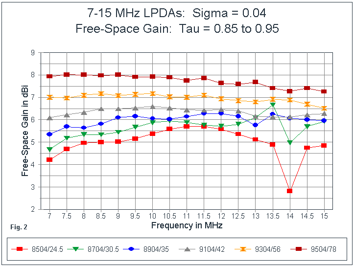
Fig. 2 shows the modeled gain values. The first thing to notice is that the higher the value of Tau, the higher the average gain of the array. However, some incremental increases appear to have greater affects on gain than others. Once Tau is greater than about 0.90, the gain difference per 0.02 change in Tau is about the same: about 0.5 dB on average. Moreover, the curves for values of Tau above 0.90 are quite well behaved.
Values of Tau below 0.90 (for a Sigma of 0.04) show two significant phenomena. First, the gain values at the lower end of the passband are more significantly lower than the peak value for the curve. Second, values at the upper end of the passband are subject to sudden erratic changes that become worse as the value of Tau decreases. We shall have further notes on both these phenomena at various places along the way in this exercise. For now, let us note that the degree of erratic change at both ends of the gain curve does correlate roughly to the number of elements in the array.
For all the curves, the gain tends to decrease toward the upper end of the passband relative to the peak value along the curve. What these 1-octave curves cannot show--in part because of the large interval between readings- -is that the gain and other properties tend to move in waves with peaks and nulls. The topmost curves for the highest values of Tau tend to indicate this wave-like movement most clearly.
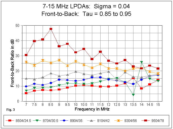
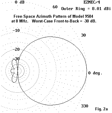
In Fig. 3, we have the 180-degree front-to-back curves for the 6 arrays. In a general way, the level of front-to-back ratio is a function of the gain at any particular place along the curves. Gain values below 5 dBi (free-space) rarely achieve a 10 dB ratio, while gain values above or close to 8 dBi are capable of front-to-back ratios of 30+ dB. In general, these high front-to-back ratios are not simply dimples in a broader front-to-rear lobe set. Rather, they represent reductions in the entire radiation pattern to the rear quadrants, as shown in Fig. 2A.
As you progress to the right in Fig. 3, you will note the same sort of erratic behavior of models with lower values of Tau. It is important to distinguish this behavior from the general trend toward reduced value in front-to-back ratios that accompanies similar gain trends for the models with the highest values of Tau. We may also note that with a Sigma of 0.04, we do not achieve a consistent front-to-back ratio in excess of 20 dB until a Tau value of .93.
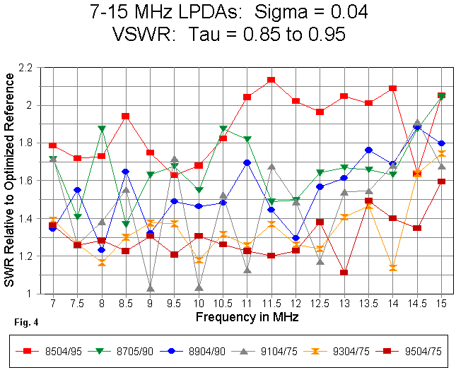
The curves for SWR in Fig. 4 form a confusing medley that requires good patience to sort. With increasing frequency, both the resistive and reactive components of the feedpoint impedance become more erratic, relative to general trends lower in the passband. Both resistance and reactance excursions show much wider limits. Hence, the selection of a reference impedance for taking the curve becomes tricky at best.
The lower values of Tau tend to show impedance excursions throughout the passband that require a higher reference impedance to derive curves in which the values surpass 2:1 at as few places as possible. In contrast, the higher values of Tau tend to yield flatter curves at the 75-Ohm reference level--again, with a 0.04 Sigma value. These curves are of greatest importance if one is interested in using the entire antenna passband. However, the SWR problem for lower values of Tau (or for shorter arrays with fewer elements) can be overcome if one is interested in only selected portions of the passband--as would be the case for purely amateur radio applications.
Before we depart these curves for a constant Sigma and variable Tau, let's look once more at the gain curves in Fig. 2. Why do the band edges tend to show lower gain values (and usually lower front-to-back ratios) than the mid-region of the passband? Part of the answer appears in Fig. 5.
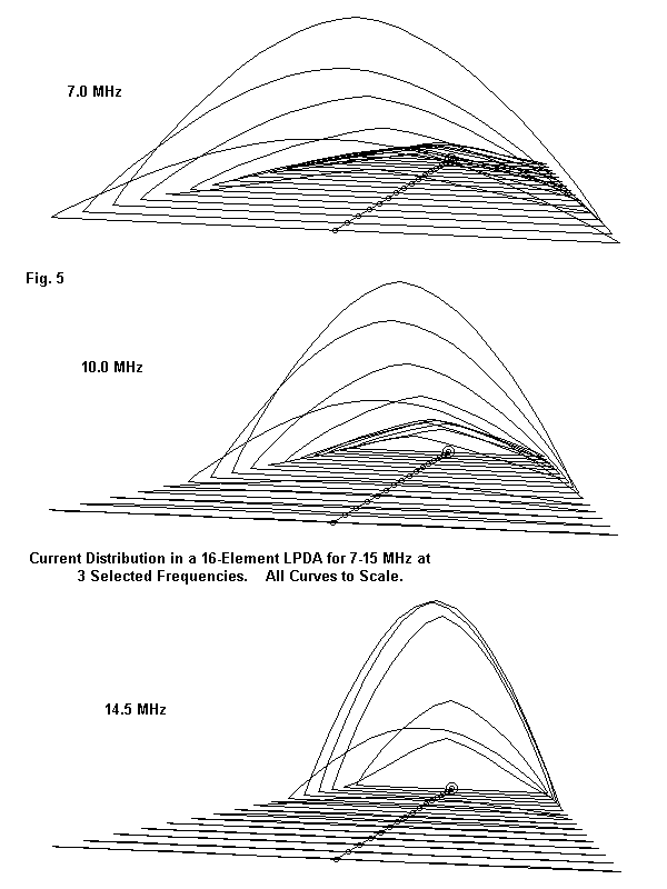
At 10 MHz for model 9304 (16 elements), there are at least 5 elements with high current levels, with several elements forward of this group having moderate current levels. Elements to the rear have lower and descending values. In essence, every element in an LPDA contributes to the pattern formation, and the number of elements with a significant current level is far higher than general LPDA gossip usually allows.
At 7 MHz, there are once more 5 elements with the highest current levels, as well as elements with some current forward of that group. However, there is no element with significant current behind the group of 5. In a large array, such as 9304, the drop of gain at the low end of the passband is small. But, in arrays with only a small number of elements, the problem of low-end gain becomes much greater. The problem of "low-end" gain would be even worse had all of the models in this exercise not been designed with a lower frequency limit of 6.8 MHz, about 3% below the operational lowest frequency. Even though standard LPDA design set the longest element at a frequency below the operationally selected low frequency, additional margins are necessary for adequate performance unless the design uses a relatively high number of elements.
At the high end of the passband, normal design procedure calculates the shortest element for a frequency 1.3 times the upper operating frequency. However, even this margin cannot fully compensate for the number of elements with moderate current levels at 10 MHz. The 15 MHz current distribution shows 6 elements with high levels, with elements to the rear having only at modest current levels. Three of the 6 high-current elements have current levels that we might associate with Yagi directors--although the function of the elements of the two antenna types differs. Missing are elements forward of the group that have moderate current levels--gradually reducing the gain at the upper frequencies of the passband.
For each of the problems we have so far noted, there are compensating techniques. However, we shall reserve mention of them for a future exercise.
To see what Sigma values might mean for performance, I chose an arbitrary value of Tau: 0.93. Actually, this value is not totally arbitrary. It is in the upper range of values. Hence, the value of Sigma is likely to have a significant effect on antenna parameters, if it has any effect at all. For the design range of 6.8 to 15 MHz, the resulting LPDAs all have 16 elements.
As noted earlier, I chose to set the lower frequency limit of the array design at 6.8 MHz rather than at the lowest operating frequency of 7.0 MHz. The result is an antenna whose performance comes nearly "up to speed" by the 7 MHz mark--unless the design has an inherently slow rise due to overall design factors.
Likewise, the antenna lengths produced by a Tau of 0.93 are not wholly outside of construction range, even in the 7-15 MHz range. Here are the array lengths for LPDA with a Tau of 0.93 and values of Sigma between 0.6 and 0.2:
Sigma          Array length (feet)      Scaled length for 14-30  Model name
0.06                83.92'                   42'                 9306
0.05                69.93'                   35'                 9305
0.04                55.94'                   28'                 9304
0.03                41.92'                   21'                 9303
0.02                27.97'                   14'                 9302
Although 84' is somewhat long for amateur construction, its scaled counterpart for 14-30 MHz is well within ham capabilities.
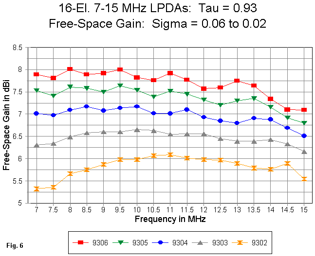
In Fig. 6, we can clearly see the "wave" motion of free-space gain values across the passband, especially for Sigma values from 0.04 upward. With a Tau as high as 0.93, the curves show much less tendency toward erratic values. Moreover, except for the lowest value of Sigma, the average gain increase for every Sigma increase of 0.01 is about 0.5 dB. The relative evenness of the gain increase with increase in the value of Sigma stands in contrast to the curve in Fig. 2. There, the gain increase itself appears to become larger as we increase Tau arithmetically. Because the curves are functions of complex geometric properties of the antenna structure-- including the individual elements lengths and spacings--a more precise quantification of the relationship would involve many other variables.
As a point of reference, model 9304 appears in the graphs for both the constant-Tau and the constant-Sigma graphs. Using this reference, we might note that the curve for model 9306 in the constant-Tau graph is roughly comparable to the curve for model 9504 in the constant-Sigma graph. The "2-point" differential in both models relative to 9304 should not go unnoticed. However, 9504 has 22 elements on a 77' boom, while 9304 has 16 elements on an 84' boom. Additional elements can go some ways toward smoothing curves and reducing the rate of higher-frequency gain decrease. Model 9505--not shown here--with a Tau of .95 and a Sigma of 0.05 shows higher gain yet than either of the two high-end models noted here.
At the other end of the scale, model 9302 is interesting, despite the fact that the Sigma value falls below recommended levels. This 14' long array shows a relatively smooth gain curve, with little sign of erratic behavior, owing to the relative high value of Tau involved. The front-to-back curve in Fig. 7 shows those values to be equally well-behaved. However, 16 elements is normally more than short-boom LPDA designers desire.
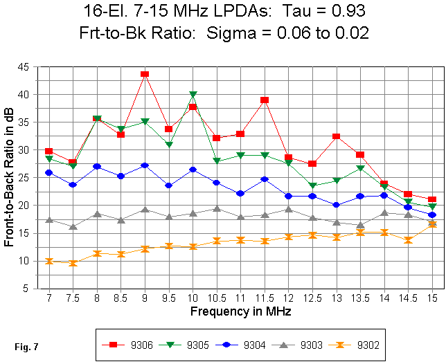
Like the gain curve, the front-to-back curve for the highest performing models in Fig. 7 shows a rapid decrease at the upper end of the passband. Arrays with a Sigma of 0.04 or higher (for a Tau of 0.93) show an average front-to-back ratio of better than 20 dB.
Interestingly, the highest performing antenna models show the most variability in front-to-back ratio. This fact stems from the shapes taken by the rearward lobes as we change frequency and other antenna characteristics. At some frequencies, the rear lobes will look like the "bowtie" of Fig. 2A. At other frequencies, the lobe will be a small "bell," which decreases the front-to-back ratio without changing the amount of energy radiated rearward. In general, one may mentally smooth all front-to-back ratio curves in excess of 30 dB without significant distortion to actual antenna performance.
Some designers believe that the second element length at the lowest operating frequency should be near resonance. This theory is incomplete, since all of the elements--place for place--in this series of models are the same length. Yet the transition from 7 to 7.5 MHz in the gain curve is upward in 4 models and downward in 2. Much more consistent is the front- to-back pattern, which shows a downward turn in all models from 7 to 7.5 MHz, with a subsequent upward turn. Only the spacing of the elements has changed in this sequence.
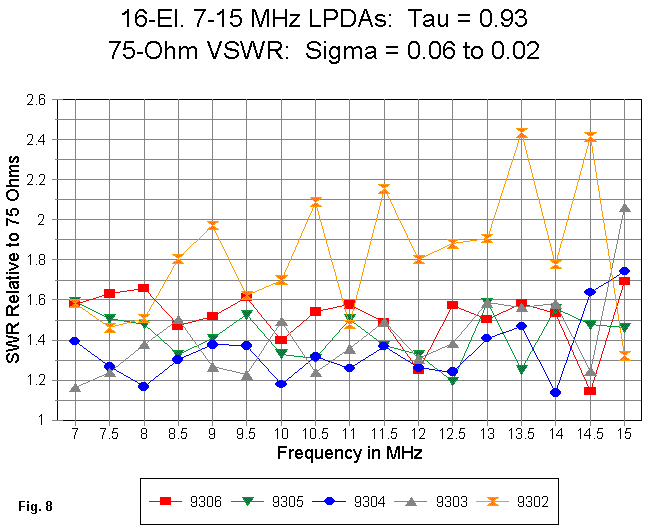
The SWR curves in Fig. 8 for the collection of LPDA designs show the usual morass of twists. All are referenced to 75 Ohms in this case for a number of reasons. Most important is the fact that as one increases the value of Sigma, using a 200-Ohm inter-element phase line, the "natural" reference impedance as we increase the value of Tau should be higher--something closer to 100 Ohms. The higher level would reduce the SWR values of these curves and better suit the arrays to the use of a wide-band 2:1 matching device for a 50-Ohm coax main feedline.
Nonetheless, all of the higher-Tau curves fall tamely within a 1.8:1 75-Ohm SWR level. Only the lower two values of Sigma result in values that exceed 2:1, and for model 9303, only at 15 MHz. In contrast is Fig. 4, the SWR curve for the constant-Sigma, variable-Tau exercise, where a number of models show values in excess of 1.8:1 when referenced to an optimized level. All of those models have Tau values of 0.91 or less, suggesting that perhaps higher Tau values tend to level SWR excursions.
Once more, model 9304, with a boom length of 56' for the 7-15 MHz range, marks a certain breaking point. LPDA arrays with Tau values of at least 0.93 AND Sigma values of at least 0.3 tend to be the most stable in almost all performance categories without any need for compensatory actions to improve the performance of the design. However, 56' (or 28' in the 20-10 meters version) is a fairly sizable array. Many hams are looking for short-booms and high performance.
Model     Length    No. of Elements     Tau       Sigma
8504      24.52'          7             0.85      0.06
9302      27.97'         16             0.93      0.02
8904      34.87'         10             0.89      0.04
8506      36.77'          7             0.89      0.06
In the graphs to follow, there is also a variant of model 8504 that we shall discuss after some more general notes on these models.
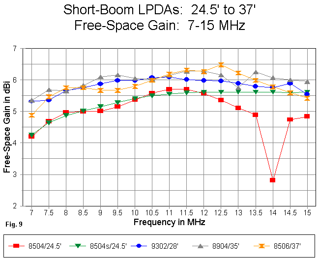
In Fig. 9 are the free-space gain curves for the models in this group. Note that they fall into two general groups. 9302, 8904, and 8506 all have very comparable gain curves, with a maximum variation of about 0.25 dB. Hence, there is little to choose among them. 9302 has the shortest boom of the lot, but also requires a higher number of elements than any other model.
The two versions of model 8504 have lesser gain, although the curves in the main are congruent with those of the higher-gain group. The precipitous drop in gain of the basic 8504 model at 14 MHz is corrected in the model called 8504s. 8504 is noteworthy for having the shortest length of all of the models.
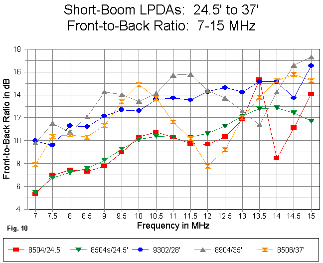
Boom length makes a difference to the front-to-back ratio as well as to gain. In Fig. 10, we can identify a 14 MHz drop in front-to-back ratio for 8504. Note, however, that the drop is preceded by an erratic rise in front-to-back ratio at 13.5 MHz. This phenomenon is not unusual: erratic performance is often forecast by an unnatural rise in performance at a slightly lower frequency.
The same generic type of forecast is offered to model 8506 by the drop in front-to-back ratio at 12 MHz, followed by a notable, but only slightly better value at 12.5 MHz. The anomaly in the performance of model 8506 is at 12.5 MHz with the sudden peak in gain--not a very large peak, but noticeable in relationship to the general trend in the curve. A similar glitch in the smooth curves occurs with model 8904 with a front-to-back warning at 13 MHz and further drop at 13.5 MHz: watch the gain curve for this model from 12.5 to 13.5 MHz.
These exceptions to smooth curves are common for short-boom LPDAs. Otherwise, the curves for front-to-back ratios again divide themselves between those for 8504 and for the longer-boom designs.
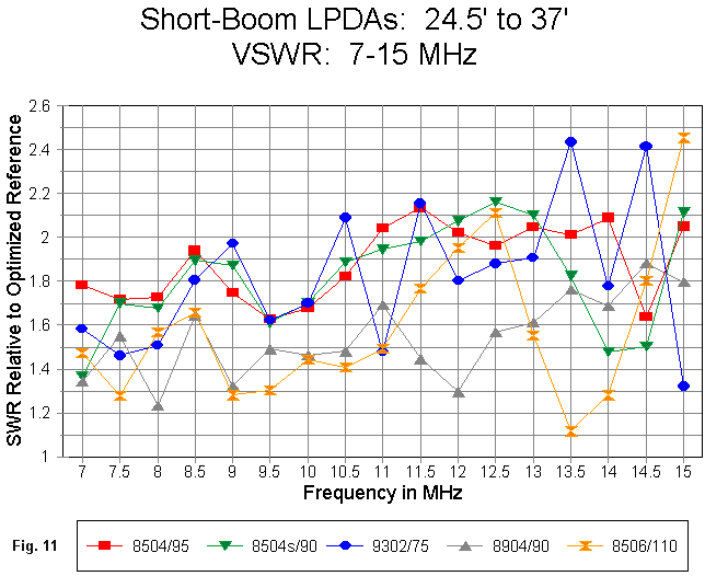
The SWR curves, set out in Fig. 11, will also show some of the same anomalies, even though they are each matched to an optimized reference impedance. With a 200-Ohm inter-element phase line, it is almost impossible to achieve a curve with values under 2:1 at the antenna feedpoint for the entirety of the passband--without using some compensatory measures or using only selected portions of the passband.
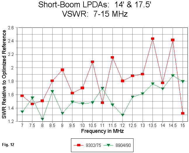
One of the models in the group is a "sleeper." That is, it has a reasonable 90-Ohm SWR curve with no value higher than 1.9. The SWR curve for model 8904 appears in Fig. 12 with the curve for 9302 as a contrast. These two antennas exhibit the best gain and front-to-back curves of the group, but 9302--with its very low value for Sigma and its 16 elements-- would still be a more difficult antenna to match to a coaxial cable. It is more likely that 8904 would work well into 50-Ohm coax with an intervening 2:1 broadband impedance matching device.
However, let's not give up on the shortest boom model, 8504, before trying to fix the anomalies in all of its curves. The critical frequency for this antenna is 14 MHz.
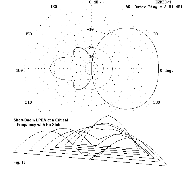
In Fig. 13, we can see the problematical azimuth pattern, as well as its source. In every other well-behaved current distribution curve, we saw only one current peak per wire, whatever the frequency within the passband and whatever the wire length. However, with 8504, the rearmost wires are operating in a true harmonic mode, with double peaks of current. These double peaks radiate both forward and rearward, widening the forward lobe and producing very significant rearward radiation. In this short-boom design with only 7 elements, the inter-element phase line is not terminated properly to prevent this mode of operation. Note also that forward-most element carries the highest current level.
The solution to the problem, known almost as long as LPDAs have been designed, is to change the termination of the rear-most element by adding a shorted stub. In model 8504s, a 36", 600-Ohm stub has been added to the rear of the model. The exact value is not critical, and further tweaking is certainly possible. The results of adding this stub are visible in all of the short-boom graphs and in Fig. 14.
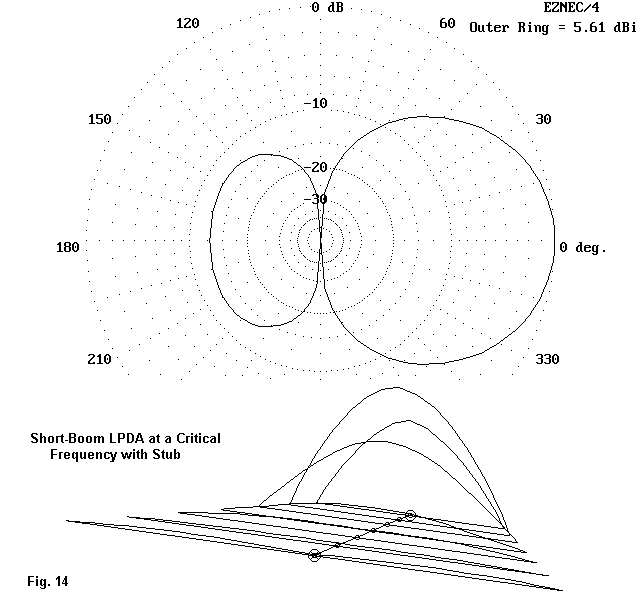
The array's gain and front-to-back ratio have been returned to normal, relative to curves for LPDAs with Tau and Sigma values in the ballpark of those for model 8504. Why this happens appears in the current distribution curve. The stub prevents the rear-most elements from operating in a harmonic mode by changing the element source impedances. In fact, the SWR for the array goes down between 13.5 and 14.5 MHz, relative to the uncorrected version. Moreover, the second most forward element now shows the highest current level, just where the peak should be for an array of this size. The array has been saved for valuable use--if operating needs call for an LPDA of this small size and for the modest gain and front-to- back characteristics it offers.
1. Changing some of the design criteria.
2. Changing the inter-element phase line impedance.
3. Varying Tau and/or Sigma along the array length.
4. Changing the element diameters.
Some of these measure are easy to implement, but others require a good bit of fundamental redesign. Since this note is already too long, we shall likely have to work up another to cover them--as soon as I finish the complete cross-matrix of models with Tau values from 0.85 to 0.95 (interval 0.02) and Sigma values from 0.02 to 0.06 (interval 0.01). Remember that we have only sampled the field, and hence, any conclusions can only be very tentative so far.
Incidentally, there is a model LPDA for the 7-15 MHz range with a gain at 7 MHz of 11.5 dBi and a gain at 14.5 of 10.3 dBi, all with a feedpoint impedance across the range that will match either 50 or 75 Ohms with smoothness and ease. Unfortunatly, the antenna's 27 elements require 434 feet.
9504.EZ EZNEC/4 ver. 2.5
6.8-15 MHz .95/.04 10-06-1999 09:10:48
Frequency = 7 MHz.
Wire Loss: Aluminum -- Resistivity = 4E-08 ohm-m, Rel. Perm. = 1
--------------- WIRES ---------------
Wire Conn. --- End 1 (x,y,z : in) Conn. --- End 2 (x,y,z : in) Dia(in) Segs
1 0.000,-442.80, 0.000 0.000,442.800, 0.000 1.00E+00 33
2 70.848,-420.66, 0.000 70.848,420.660, 0.000 1.00E+00 31
3 138.154,-399.63, 0.000 138.154,399.627, 0.000 1.00E+00 29
4 202.094,-379.65, 0.000 202.094,379.646, 0.000 1.00E+00 27
5 262.837,-360.66, 0.000 262.837,360.663, 0.000 1.00E+00 27
6 320.543,-342.63, 0.000 320.543,342.630, 0.000 1.00E+00 25
7 375.364,-325.50, 0.000 375.364,325.499, 0.000 1.00E+00 23
8 427.444,-309.22, 0.000 427.444,309.224, 0.000 1.00E+00 23
9 476.920,-293.76, 0.000 476.920,293.763, 0.000 1.00E+00 21
10 523.922,-279.07, 0.000 523.922,279.074, 0.000 1.00E+00 21
11 568.574,-265.12, 0.000 568.574,265.121, 0.000 1.00E+00 19
12 610.993,-251.86, 0.000 610.993,251.865, 0.000 1.00E+00 19
13 651.291,-239.27, 0.000 651.291,239.271, 0.000 1.00E+00 17
14 689.575,-227.31, 0.000 689.575,227.308, 0.000 1.00E+00 17
15 725.944,-215.94, 0.000 725.944,215.942, 0.000 1.00E+00 15
16 760.495,-205.15, 0.000 760.495,205.145, 0.000 1.00E+00 15
17 793.318,-194.89, 0.000 793.318,194.888, 0.000 1.00E+00 15
18 824.500,-185.14, 0.000 824.500,185.144, 0.000 1.00E+00 13
19 854.123,-175.89, 0.000 854.123,175.887, 0.000 1.00E+00 13
20 882.265,-167.09, 0.000 882.265,167.092, 0.000 1.00E+00 13
21 909.000,-158.74, 0.000 909.000,158.738, 0.000 1.00E+00 11
22 934.398,-150.80, 0.000 934.398,150.801, 0.000 1.00E+00 11
-------------- SOURCES --------------
Source Wire Wire #/Pct From End 1 Ampl.(V, A) Phase(Deg.) Type
Seg. Actual (Specified)
1 6 22 / 50.00 ( 22 / 50.00) 0.707 0.000 V
No loads specified
-------- TRANSMISSION LINES ---------
Line Wire #/% From End 1 Wire #/% From End 1 Length Z0 Vel Rev/
Actual (Specified) Actual (Specified) Ohms Fact Norm
1 1/50.0 ( 1/50.0) 2/50.0 ( 2/50.0) Actual dist 200.0 1.00 R
2 2/50.0 ( 2/50.0) 3/50.0 ( 3/50.0) Actual dist 200.0 1.00 R
3 3/50.0 ( 3/50.0) 4/50.0 ( 4/50.0) Actual dist 200.0 1.00 R
4 4/50.0 ( 4/50.0) 5/50.0 ( 5/50.0) Actual dist 200.0 1.00 R
5 5/50.0 ( 5/50.0) 6/50.0 ( 6/50.0) Actual dist 200.0 1.00 R
6 6/50.0 ( 6/50.0) 7/50.0 ( 7/50.0) Actual dist 200.0 1.00 R
7 7/50.0 ( 7/50.0) 8/50.0 ( 8/50.0) Actual dist 200.0 1.00 R
8 8/50.0 ( 8/50.0) 9/50.0 ( 9/50.0) Actual dist 200.0 1.00 R
9 9/50.0 ( 9/50.0) 10/50.0 ( 10/50.0) Actual dist 200.0 1.00 R
10 10/50.0 ( 10/50.0) 11/50.0 ( 11/50.0) Actual dist 200.0 1.00 R
11 11/50.0 ( 11/50.0) 12/50.0 ( 12/50.0) Actual dist 200.0 1.00 R
12 12/50.0 ( 12/50.0) 13/50.0 ( 13/50.0) Actual dist 200.0 1.00 R
13 13/50.0 ( 13/50.0) 14/50.0 ( 14/50.0) Actual dist 200.0 1.00 R
14 14/50.0 ( 14/50.0) 15/50.0 ( 15/50.0) Actual dist 200.0 1.00 R
15 15/50.0 ( 15/50.0) 16/50.0 ( 16/50.0) Actual dist 200.0 1.00 R
16 16/50.0 ( 16/50.0) 17/50.0 ( 17/50.0) Actual dist 200.0 1.00 R
17 17/50.0 ( 17/50.0) 18/50.0 ( 18/50.0) Actual dist 200.0 1.00 R
18 18/50.0 ( 18/50.0) 19/50.0 ( 19/50.0) Actual dist 200.0 1.00 R
19 19/50.0 ( 19/50.0) 20/50.0 ( 20/50.0) Actual dist 200.0 1.00 R
20 20/50.0 ( 20/50.0) 21/50.0 ( 21/50.0) Actual dist 200.0 1.00 R
21 21/50.0 ( 21/50.0) 22/50.0 ( 22/50.0) Actual dist 200.0 1.00 R
Ground type is Free Space
. . . . . . . . . . . . . . . . . . . . . . . . . . . . . . . . . . . . . . .
9104.EZ EZNEC/4 ver. 2.5
6.8-15 MHz .91/.04 10-06-1999 09:06:32
Frequency = 7 MHz.
Wire Loss: Aluminum -- Resistivity = 4E-08 ohm-m, Rel. Perm. = 1
--------------- WIRES ---------------
Wire Conn. --- End 1 (x,y,z : in) Conn. --- End 2 (x,y,z : in) Dia(in) Segs
1 0.000,-442.80, 0.000 0.000,442.800, 0.000 1.00E+00 31
2 70.848,-402.95, 0.000 70.848,402.948, 0.000 1.00E+00 29
3 135.320,-366.68, 0.000 135.320,366.683, 0.000 1.00E+00 25
4 193.989,-333.68, 0.000 193.989,333.681, 0.000 1.00E+00 23
5 247.378,-303.65, 0.000 247.378,303.650, 0.000 1.00E+00 21
6 295.962,-276.32, 0.000 295.962,276.321, 0.000 1.00E+00 19
7 340.173,-251.45, 0.000 340.173,251.452, 0.000 1.00E+00 17
8 380.406,-228.82, 0.000 380.406,228.822, 0.000 1.00E+00 17
9 417.017,-208.23, 0.000 417.017,208.228, 0.000 1.00E+00 15
10 450.334,-189.49, 0.000 450.334,189.487, 0.000 1.00E+00 13
11 480.652,-172.43, 0.000 480.652,172.434, 0.000 1.00E+00 13
12 508.241,-156.91, 0.000 508.241,156.915, 0.000 1.00E+00 11
-------------- SOURCES --------------
Source Wire Wire #/Pct From End 1 Ampl.(V, A) Phase(Deg.) Type
Seg. Actual (Specified)
1 6 12 / 50.00 ( 12 / 50.00) 0.707 0.000 V
No loads specified
-------- TRANSMISSION LINES ---------
Line Wire #/% From End 1 Wire #/% From End 1 Length Z0 Vel Rev/
Actual (Specified) Actual (Specified) Ohms Fact Norm
1 1/50.0 ( 1/50.0) 2/50.0 ( 2/50.0) Actual dist 200.0 1.00 R
2 2/50.0 ( 2/50.0) 3/50.0 ( 3/50.0) Actual dist 200.0 1.00 R
3 3/50.0 ( 3/50.0) 4/50.0 ( 4/50.0) Actual dist 200.0 1.00 R
4 4/50.0 ( 4/50.0) 5/50.0 ( 5/50.0) Actual dist 200.0 1.00 R
5 5/50.0 ( 5/50.0) 6/50.0 ( 6/50.0) Actual dist 200.0 1.00 R
6 6/50.0 ( 6/50.0) 7/50.0 ( 7/50.0) Actual dist 200.0 1.00 R
7 7/50.0 ( 7/50.0) 8/50.0 ( 8/50.0) Actual dist 200.0 1.00 R
8 8/50.0 ( 8/50.0) 9/50.0 ( 9/50.0) Actual dist 200.0 1.00 R
9 9/50.0 ( 9/50.0) 10/50.0 ( 10/50.0) Actual dist 200.0 1.00 R
10 10/50.0 ( 10/50.0) 11/50.0 ( 11/50.0) Actual dist 200.0 1.00 R
11 11/50.0 ( 11/50.0) 12/50.0 ( 12/50.0) Actual dist 200.0 1.00 R
Ground type is Free Space
. . . . . . . . . . . . . . . . . . . . . . . . . . . . . . . . . . . . . . .
8704.EZ EZNEC/4 ver. 2.5
6.8-15 .87/.04\ 10-06-1999 09:05:47
Frequency = 7 MHz.
Wire Loss: Aluminum -- Resistivity = 4E-08 ohm-m, Rel. Perm. = 1
--------------- WIRES ---------------
Wire Conn. --- End 1 (x,y,z : in) Conn. --- End 2 (x,y,z : in) Dia(in) Segs
1 0.000,-442.80, 0.000 0.000,442.800, 0.000 1.00E+00 33
2 70.848,-385.24, 0.000 70.848,385.236, 0.000 1.00E+00 29
3 132.486,-335.16, 0.000 132.486,335.155, 0.000 1.00E+00 25
4 186.111,-291.59, 0.000 186.111,291.585, 0.000 1.00E+00 23
5 232.764,-253.68, 0.000 232.764,253.679, 0.000 1.00E+00 19
6 273.353,-220.70, 0.000 273.353,220.701, 0.000 1.00E+00 17
7 308.665,-192.01, 0.000 308.665,192.010, 0.000 1.00E+00 15
8 339.387,-167.05, 0.000 339.387,167.048, 0.000 1.00E+00 13
9 366.114,-145.33, 0.000 366.114,145.332, 0.000 1.00E+00 11
-------------- SOURCES --------------
Source Wire Wire #/Pct From End 1 Ampl.(V, A) Phase(Deg.) Type
Seg. Actual (Specified)
1 6 9 / 50.00 ( 9 / 50.00) 0.707 0.000 V
No loads specified
-------- TRANSMISSION LINES ---------
Line Wire #/% From End 1 Wire #/% From End 1 Length Z0 Vel Rev/
Actual (Specified) Actual (Specified) Ohms Fact Norm
1 1/50.0 ( 1/50.0) 2/50.0 ( 2/50.0) Actual dist 200.0 1.00 R
2 2/50.0 ( 2/50.0) 3/50.0 ( 3/50.0) Actual dist 200.0 1.00 R
3 3/50.0 ( 3/50.0) 4/50.0 ( 4/50.0) Actual dist 200.0 1.00 R
4 4/50.0 ( 4/50.0) 5/50.0 ( 5/50.0) Actual dist 200.0 1.00 R
5 5/50.0 ( 5/50.0) 6/50.0 ( 6/50.0) Actual dist 200.0 1.00 R
6 6/50.0 ( 6/50.0) 7/50.0 ( 7/50.0) Actual dist 200.0 1.00 R
7 7/50.0 ( 7/50.0) 8/50.0 ( 8/50.0) Actual dist 200.0 1.00 R
8 8/50.0 ( 8/50.0) 9/50.0 ( 9/50.0) Actual dist 200.0 1.00 R
Ground type is Free Space
. . . . . . . . . . . . . . . . . . . . . . . . . . . . . . . . . . . . . . .
9306.EZ EZNEC/4 ver. 2.5
6.8-15 MHz 16 el .93/.06 10-05-1999 11:28:11
Frequency = 7 MHz.
Wire Loss: Aluminum -- Resistivity = 4E-08 ohm-m, Rel. Perm. = 1
--------------- WIRES ---------------
Wire Conn. --- End 1 (x,y,z : in) Conn. --- End 2 (x,y,z : in) Dia(in) Segs
1 0.000,-442.80, 0.000 0.000,442.800, 0.000 1.00E+00 27
2 106.272,-411.80, 0.000 106.272,411.804, 0.000 1.00E+00 27
3 205.105,-382.98, 0.000 205.105,382.978, 0.000 1.00E+00 25
4 297.020,-356.17, 0.000 297.020,356.169, 0.000 1.00E+00 23
5 382.500,-331.24, 0.000 382.500,331.237, 0.000 1.00E+00 21
6 461.997,-308.05, 0.000 461.997,308.051, 0.000 1.00E+00 21
7 535.929,-286.49, 0.000 535.929,286.487, 0.000 1.00E+00 19
8 604.686,-266.43, 0.000 604.686,266.433, 0.000 1.00E+00 19
9 668.630,-247.78, 0.000 668.630,247.783, 0.000 1.00E+00 17
10 728.098,-230.44, 0.000 728.098,230.438, 0.000 1.00E+00 15
11 783.403,-214.31, 0.000 783.403,214.307, 0.000 1.00E+00 15
12 834.837,-199.31, 0.000 834.837,199.306, 0.000 1.00E+00 15
13 882.670,-185.35, 0.000 882.670,185.354, 0.000 1.00E+00 13
14 927.156,-172.38, 0.000 927.156,172.380, 0.000 1.00E+00 13
15 968.527,-160.31, 0.000 968.527,160.313, 0.000 1.00E+00 11
16 1007.00,-149.09, 0.000 1007.00,149.091, 0.000 1.00E+00 11
-------------- SOURCES --------------
Source Wire Wire #/Pct From End 1 Ampl.(V, A) Phase(Deg.) Type
Seg. Actual (Specified)
1 6 16 / 50.00 ( 16 / 50.00) 0.707 0.000 V
No loads specified
-------- TRANSMISSION LINES ---------
Line Wire #/% From End 1 Wire #/% From End 1 Length Z0 Vel Rev/
Actual (Specified) Actual (Specified) Ohms Fact Norm
1 1/50.0 ( 1/50.0) 2/50.0 ( 2/50.0) Actual dist 200.0 1.00 R
2 2/50.0 ( 2/50.0) 3/50.0 ( 3/50.0) Actual dist 200.0 1.00 R
3 3/50.0 ( 3/50.0) 4/50.0 ( 4/50.0) Actual dist 200.0 1.00 R
4 4/50.0 ( 4/50.0) 5/50.0 ( 5/50.0) Actual dist 200.0 1.00 R
5 5/50.0 ( 5/50.0) 6/50.0 ( 6/50.0) Actual dist 200.0 1.00 R
6 6/50.0 ( 6/50.0) 7/50.0 ( 7/50.0) Actual dist 200.0 1.00 R
7 7/50.0 ( 7/50.0) 8/50.0 ( 8/50.0) Actual dist 200.0 1.00 R
8 8/50.0 ( 8/50.0) 9/50.0 ( 9/50.0) Actual dist 200.0 1.00 R
9 9/50.0 ( 9/50.0) 10/50.0 ( 10/50.0) Actual dist 200.0 1.00 R
10 10/50.0 ( 10/50.0) 11/50.0 ( 11/50.0) Actual dist 200.0 1.00 R
11 11/50.0 ( 11/50.0) 12/50.0 ( 12/50.0) Actual dist 200.0 1.00 R
12 12/50.0 ( 12/50.0) 13/50.0 ( 13/50.0) Actual dist 200.0 1.00 R
13 13/50.0 ( 13/50.0) 14/50.0 ( 14/50.0) Actual dist 200.0 1.00 R
14 14/50.0 ( 14/50.0) 15/50.0 ( 15/50.0) Actual dist 200.0 1.00 R
15 15/50.0 ( 15/50.0) 16/50.0 ( 16/50.0) Actual dist 200.0 1.00 R
Ground type is Free Space
. . . . . . . . . . . . . . . . . . . . . . . . . . . . . . . . . . . . . . .
9305.EZ EZNEC/4 ver. 2.5
6.8-15 MHz 16 el .93/.05 10-05-1999 11:27:38
Frequency = 7 MHz.
Wire Loss: Aluminum -- Resistivity = 4E-08 ohm-m, Rel. Perm. = 1
--------------- WIRES ---------------
Wire Conn. --- End 1 (x,y,z : in) Conn. --- End 2 (x,y,z : in) Dia(in) Segs
1 0.000,-442.80, 0.000 0.000,442.800, 0.000 1.00E+00 27
2 88.560,-411.80, 0.000 88.560,411.804, 0.000 1.00E+00 27
3 170.921,-382.98, 0.000 170.921,382.978, 0.000 1.00E+00 25
4 247.516,-356.17, 0.000 247.516,356.169, 0.000 1.00E+00 23
5 318.750,-331.24, 0.000 318.750,331.237, 0.000 1.00E+00 21
6 384.998,-308.05, 0.000 384.998,308.051, 0.000 1.00E+00 21
7 446.608,-286.49, 0.000 446.608,286.487, 0.000 1.00E+00 19
8 503.905,-266.43, 0.000 503.905,266.433, 0.000 1.00E+00 19
9 557.192,-247.78, 0.000 557.192,247.783, 0.000 1.00E+00 17
10 606.748,-230.44, 0.000 606.748,230.438, 0.000 1.00E+00 15
11 652.836,-214.31, 0.000 652.836,214.307, 0.000 1.00E+00 15
12 695.698,-199.31, 0.000 695.698,199.306, 0.000 1.00E+00 15
13 735.559,-185.35, 0.000 735.559,185.354, 0.000 1.00E+00 13
14 772.630,-172.38, 0.000 772.630,172.380, 0.000 1.00E+00 13
15 807.106,-160.31, 0.000 807.106,160.313, 0.000 1.00E+00 11
16 839.168,-149.09, 0.000 839.168,149.091, 0.000 1.00E+00 11
-------------- SOURCES --------------
Source Wire Wire #/Pct From End 1 Ampl.(V, A) Phase(Deg.) Type
Seg. Actual (Specified)
1 6 16 / 50.00 ( 16 / 50.00) 0.707 0.000 V
No loads specified
-------- TRANSMISSION LINES ---------
Line Wire #/% From End 1 Wire #/% From End 1 Length Z0 Vel Rev/
Actual (Specified) Actual (Specified) Ohms Fact Norm
1 1/50.0 ( 1/50.0) 2/50.0 ( 2/50.0) Actual dist 200.0 1.00 R
2 2/50.0 ( 2/50.0) 3/50.0 ( 3/50.0) Actual dist 200.0 1.00 R
3 3/50.0 ( 3/50.0) 4/50.0 ( 4/50.0) Actual dist 200.0 1.00 R
4 4/50.0 ( 4/50.0) 5/50.0 ( 5/50.0) Actual dist 200.0 1.00 R
5 5/50.0 ( 5/50.0) 6/50.0 ( 6/50.0) Actual dist 200.0 1.00 R
6 6/50.0 ( 6/50.0) 7/50.0 ( 7/50.0) Actual dist 200.0 1.00 R
7 7/50.0 ( 7/50.0) 8/50.0 ( 8/50.0) Actual dist 200.0 1.00 R
8 8/50.0 ( 8/50.0) 9/50.0 ( 9/50.0) Actual dist 200.0 1.00 R
9 9/50.0 ( 9/50.0) 10/50.0 ( 10/50.0) Actual dist 200.0 1.00 R
10 10/50.0 ( 10/50.0) 11/50.0 ( 11/50.0) Actual dist 200.0 1.00 R
11 11/50.0 ( 11/50.0) 12/50.0 ( 12/50.0) Actual dist 200.0 1.00 R
12 12/50.0 ( 12/50.0) 13/50.0 ( 13/50.0) Actual dist 200.0 1.00 R
13 13/50.0 ( 13/50.0) 14/50.0 ( 14/50.0) Actual dist 200.0 1.00 R
14 14/50.0 ( 14/50.0) 15/50.0 ( 15/50.0) Actual dist 200.0 1.00 R
15 15/50.0 ( 15/50.0) 16/50.0 ( 16/50.0) Actual dist 200.0 1.00 R
Ground type is Free Space
. . . . . . . . . . . . . . . . . . . . . . . . . . . . . . . . . . . . . . .
9304.EZ EZNEC/4 ver. 2.5
.93/.04 6.88-15 MHz 10-05-1999 11:27:02
Frequency = 7 MHz.
Wire Loss: Aluminum -- Resistivity = 4E-08 ohm-m, Rel. Perm. = 1
--------------- WIRES ---------------
Wire Conn. --- End 1 (x,y,z : in) Conn. --- End 2 (x,y,z : in) Dia(in) Segs
1 0.000,-442.80, 0.000 0.000,442.800, 0.000 1.00E+00 27
2 70.848,-411.80, 0.000 70.848,411.804, 0.000 1.00E+00 27
3 136.737,-382.98, 0.000 136.737,382.978, 0.000 1.00E+00 25
4 198.013,-356.17, 0.000 198.013,356.169, 0.000 1.00E+00 23
5 255.000,-331.24, 0.000 255.000,331.237, 0.000 1.00E+00 21
6 307.998,-308.05, 0.000 307.998,308.051, 0.000 1.00E+00 21
7 357.286,-286.49, 0.000 357.286,286.487, 0.000 1.00E+00 19
8 403.124,-266.43, 0.000 403.124,266.433, 0.000 1.00E+00 19
9 445.754,-247.78, 0.000 445.754,247.783, 0.000 1.00E+00 17
10 485.399,-230.44, 0.000 485.399,230.438, 0.000 1.00E+00 15
11 522.269,-214.31, 0.000 522.269,214.307, 0.000 1.00E+00 15
12 556.558,-199.31, 0.000 556.558,199.306, 0.000 1.00E+00 15
13 588.447,-185.35, 0.000 588.447,185.354, 0.000 1.00E+00 13
14 618.104,-172.38, 0.000 618.104,172.380, 0.000 1.00E+00 13
15 645.684,-160.31, 0.000 645.684,160.313, 0.000 1.00E+00 11
16 671.334,-149.09, 0.000 671.334,149.091, 0.000 1.00E+00 11
-------------- SOURCES --------------
Source Wire Wire #/Pct From End 1 Ampl.(V, A) Phase(Deg.) Type
Seg. Actual (Specified)
1 6 16 / 50.00 ( 16 / 50.00) 0.707 0.000 V
No loads specified
-------- TRANSMISSION LINES ---------
Line Wire #/% From End 1 Wire #/% From End 1 Length Z0 Vel Rev/
Actual (Specified) Actual (Specified) Ohms Fact Norm
1 1/50.0 ( 1/50.0) 2/50.0 ( 2/50.0) Actual dist 200.0 1.00 R
2 2/50.0 ( 2/50.0) 3/50.0 ( 3/50.0) Actual dist 200.0 1.00 R
3 3/50.0 ( 3/50.0) 4/50.0 ( 4/50.0) Actual dist 200.0 1.00 R
4 4/50.0 ( 4/50.0) 5/50.0 ( 5/50.0) Actual dist 200.0 1.00 R
5 5/50.0 ( 5/50.0) 6/50.0 ( 6/50.0) Actual dist 200.0 1.00 R
6 6/50.0 ( 6/50.0) 7/50.0 ( 7/50.0) Actual dist 200.0 1.00 R
7 7/50.0 ( 7/50.0) 8/50.0 ( 8/50.0) Actual dist 200.0 1.00 R
8 8/50.0 ( 8/50.0) 9/50.0 ( 9/50.0) Actual dist 200.0 1.00 R
9 9/50.0 ( 9/50.0) 10/50.0 ( 10/50.0) Actual dist 200.0 1.00 R
10 10/50.0 ( 10/50.0) 11/50.0 ( 11/50.0) Actual dist 200.0 1.00 R
11 11/50.0 ( 11/50.0) 12/50.0 ( 12/50.0) Actual dist 200.0 1.00 R
12 12/50.0 ( 12/50.0) 13/50.0 ( 13/50.0) Actual dist 200.0 1.00 R
13 13/50.0 ( 13/50.0) 14/50.0 ( 14/50.0) Actual dist 200.0 1.00 R
14 14/50.0 ( 14/50.0) 15/50.0 ( 15/50.0) Actual dist 200.0 1.00 R
15 15/50.0 ( 15/50.0) 16/50.0 ( 16/50.0) Actual dist 200.0 1.00 R
Ground type is Free Space
. . . . . . . . . . . . . . . . . . . . . . . . . . . . . . . . . . . . . . .
9303.EZ EZNEC/4 ver. 2.5
.98/.03 6.8-15 MHz 10-05-1999 11:26:29
Frequency = 7 MHz.
Wire Loss: Aluminum -- Resistivity = 4E-08 ohm-m, Rel. Perm. = 1
--------------- WIRES ---------------
Wire Conn. --- End 1 (x,y,z : in) Conn. --- End 2 (x,y,z : in) Dia(in) Segs
1 0.000,-442.80, 0.000 0.000,442.800, 0.000 1.00E+00 27
2 53.136,-411.80, 0.000 53.136,411.804, 0.000 1.00E+00 27
3 102.552,-382.98, 0.000 102.552,382.978, 0.000 1.00E+00 25
4 148.510,-356.17, 0.000 148.510,356.169, 0.000 1.00E+00 23
5 191.250,-331.24, 0.000 191.250,331.237, 0.000 1.00E+00 21
6 230.999,-308.05, 0.000 230.999,308.051, 0.000 1.00E+00 21
7 267.965,-286.49, 0.000 267.965,286.487, 0.000 1.00E+00 19
8 302.343,-266.43, 0.000 302.343,266.433, 0.000 1.00E+00 19
9 334.315,-247.78, 0.000 334.315,247.783, 0.000 1.00E+00 17
10 364.049,-230.44, 0.000 364.049,230.438, 0.000 1.00E+00 15
11 391.702,-214.31, 0.000 391.702,214.307, 0.000 1.00E+00 15
12 417.418,-199.31, 0.000 417.418,199.306, 0.000 1.00E+00 15
13 441.335,-185.35, 0.000 441.335,185.354, 0.000 1.00E+00 13
14 463.578,-172.38, 0.000 463.578,172.380, 0.000 1.00E+00 13
15 484.263,-160.31, 0.000 484.263,160.313, 0.000 1.00E+00 11
16 503.501,-149.09, 0.000 503.501,149.091, 0.000 1.00E+00 11
-------------- SOURCES --------------
Source Wire Wire #/Pct From End 1 Ampl.(V, A) Phase(Deg.) Type
Seg. Actual (Specified)
1 6 16 / 50.00 ( 16 / 50.00) 0.707 0.000 V
No loads specified
-------- TRANSMISSION LINES ---------
Line Wire #/% From End 1 Wire #/% From End 1 Length Z0 Vel Rev/
Actual (Specified) Actual (Specified) Ohms Fact Norm
1 1/50.0 ( 1/50.0) 2/50.0 ( 2/50.0) Actual dist 200.0 1.00 R
2 2/50.0 ( 2/50.0) 3/50.0 ( 3/50.0) Actual dist 200.0 1.00 R
3 3/50.0 ( 3/50.0) 4/50.0 ( 4/50.0) Actual dist 200.0 1.00 R
4 4/50.0 ( 4/50.0) 5/50.0 ( 5/50.0) Actual dist 200.0 1.00 R
5 5/50.0 ( 5/50.0) 6/50.0 ( 6/50.0) Actual dist 200.0 1.00 R
6 6/50.0 ( 6/50.0) 7/50.0 ( 7/50.0) Actual dist 200.0 1.00 R
7 7/50.0 ( 7/50.0) 8/50.0 ( 8/50.0) Actual dist 200.0 1.00 R
8 8/50.0 ( 8/50.0) 9/50.0 ( 9/50.0) Actual dist 200.0 1.00 R
9 9/50.0 ( 9/50.0) 10/50.0 ( 10/50.0) Actual dist 200.0 1.00 R
10 10/50.0 ( 10/50.0) 11/50.0 ( 11/50.0) Actual dist 200.0 1.00 R
11 11/50.0 ( 11/50.0) 12/50.0 ( 12/50.0) Actual dist 200.0 1.00 R
12 12/50.0 ( 12/50.0) 13/50.0 ( 13/50.0) Actual dist 200.0 1.00 R
13 13/50.0 ( 13/50.0) 14/50.0 ( 14/50.0) Actual dist 200.0 1.00 R
14 14/50.0 ( 14/50.0) 15/50.0 ( 15/50.0) Actual dist 200.0 1.00 R
15 15/50.0 ( 15/50.0) 16/50.0 ( 16/50.0) Actual dist 200.0 1.00 R
Ground type is Free Space
. . . . . . . . . . . . . . . . . . . . . . . . . . . . . . . . . . . . . . .
9302.EZ EZNEC/4 ver. 2.5
.93/.02 6.88-15 MHz 10-05-1999 11:24:47
Frequency = 7 MHz.
Wire Loss: Aluminum -- Resistivity = 4E-08 ohm-m, Rel. Perm. = 1
--------------- WIRES ---------------
Wire Conn. --- End 1 (x,y,z : in) Conn. --- End 2 (x,y,z : in) Dia(in) Segs
1 0.000,-442.80, 0.000 0.000,442.800, 0.000 1.00E+00 27
2 35.424,-411.80, 0.000 35.424,411.804, 0.000 1.00E+00 27
3 68.369,-382.98, 0.000 68.369,382.978, 0.000 1.00E+00 25
4 99.007,-356.17, 0.000 99.007,356.169, 0.000 1.00E+00 23
5 127.500,-331.24, 0.000 127.500,331.237, 0.000 1.00E+00 21
6 153.999,-308.05, 0.000 153.999,308.051, 0.000 1.00E+00 21
7 178.643,-286.49, 0.000 178.643,286.487, 0.000 1.00E+00 19
8 201.562,-266.43, 0.000 201.562,266.433, 0.000 1.00E+00 19
9 222.877,-247.78, 0.000 222.877,247.783, 0.000 1.00E+00 17
10 242.700,-230.44, 0.000 242.700,230.438, 0.000 1.00E+00 15
11 261.135,-214.31, 0.000 261.135,214.307, 0.000 1.00E+00 15
12 278.279,-199.31, 0.000 278.279,199.306, 0.000 1.00E+00 15
13 294.224,-185.35, 0.000 294.224,185.354, 0.000 1.00E+00 13
14 309.052,-172.38, 0.000 309.052,172.380, 0.000 1.00E+00 13
15 322.842,-160.31, 0.000 322.842,160.313, 0.000 1.00E+00 11
16 335.668,-149.09, 0.000 335.668,149.091, 0.000 1.00E+00 11
-------------- SOURCES --------------
Source Wire Wire #/Pct From End 1 Ampl.(V, A) Phase(Deg.) Type
Seg. Actual (Specified)
1 6 16 / 50.00 ( 16 / 50.00) 0.707 0.000 V
No loads specified
-------- TRANSMISSION LINES ---------
Line Wire #/% From End 1 Wire #/% From End 1 Length Z0 Vel Rev/
Actual (Specified) Actual (Specified) Ohms Fact Norm
1 1/50.0 ( 1/50.0) 2/50.0 ( 2/50.0) Actual dist 200.0 1.00 R
2 2/50.0 ( 2/50.0) 3/50.0 ( 3/50.0) Actual dist 200.0 1.00 R
3 3/50.0 ( 3/50.0) 4/50.0 ( 4/50.0) Actual dist 200.0 1.00 R
4 4/50.0 ( 4/50.0) 5/50.0 ( 5/50.0) Actual dist 200.0 1.00 R
5 5/50.0 ( 5/50.0) 6/50.0 ( 6/50.0) Actual dist 200.0 1.00 R
6 6/50.0 ( 6/50.0) 7/50.0 ( 7/50.0) Actual dist 200.0 1.00 R
7 7/50.0 ( 7/50.0) 8/50.0 ( 8/50.0) Actual dist 200.0 1.00 R
8 8/50.0 ( 8/50.0) 9/50.0 ( 9/50.0) Actual dist 200.0 1.00 R
9 9/50.0 ( 9/50.0) 10/50.0 ( 10/50.0) Actual dist 200.0 1.00 R
10 10/50.0 ( 10/50.0) 11/50.0 ( 11/50.0) Actual dist 200.0 1.00 R
11 11/50.0 ( 11/50.0) 12/50.0 ( 12/50.0) Actual dist 200.0 1.00 R
12 12/50.0 ( 12/50.0) 13/50.0 ( 13/50.0) Actual dist 200.0 1.00 R
13 13/50.0 ( 13/50.0) 14/50.0 ( 14/50.0) Actual dist 200.0 1.00 R
14 14/50.0 ( 14/50.0) 15/50.0 ( 15/50.0) Actual dist 200.0 1.00 R
15 15/50.0 ( 15/50.0) 16/50.0 ( 16/50.0) Actual dist 200.0 1.00 R
Ground type is Free Space
. . . . . . . . . . . . . . . . . . . . . . . . . . . . . . . . . . . . . . .
8506.EZ EZNEC/4 ver. 2.5
6.8-15 MHz .85/.06 10-05-1999 11:26:03
Frequency = 7 MHz.
Wire Loss: Aluminum -- Resistivity = 4E-08 ohm-m, Rel. Perm. = 1
--------------- WIRES ---------------
Wire Conn. --- End 1 (x,y,z : in) Conn. --- End 2 (x,y,z : in) Dia(in) Segs
1 0.000,-442.80, 0.000 0.000,442.800, 0.000 1.00E+00 29
2 106.272,-376.38, 0.000 106.272,376.380, 0.000 1.00E+00 25
3 196.603,-319.92, 0.000 196.603,319.923, 0.000 1.00E+00 21
4 273.385,-271.93, 0.000 273.385,271.935, 0.000 1.00E+00 17
5 338.649,-231.14, 0.000 338.649,231.144, 0.000 1.00E+00 15
6 394.124,-196.47, 0.000 394.124,196.473, 0.000 1.00E+00 13
7 441.277,-167.00, 0.000 441.277,167.002, 0.000 1.00E+00 11
-------------- SOURCES --------------
Source Wire Wire #/Pct From End 1 Ampl.(V, A) Phase(Deg.) Type
Seg. Actual (Specified)
1 6 7 / 50.00 ( 7 / 50.00) 0.707 0.000 V
No loads specified
-------- TRANSMISSION LINES ---------
Line Wire #/% From End 1 Wire #/% From End 1 Length Z0 Vel Rev/
Actual (Specified) Actual (Specified) Ohms Fact Norm
1 1/50.0 ( 1/50.0) 2/50.0 ( 2/50.0) Actual dist 200.0 1.00 R
2 2/50.0 ( 2/50.0) 3/50.0 ( 3/50.0) Actual dist 200.0 1.00 R
3 3/50.0 ( 3/50.0) 4/50.0 ( 4/50.0) Actual dist 200.0 1.00 R
4 4/50.0 ( 4/50.0) 5/50.0 ( 5/50.0) Actual dist 200.0 1.00 R
5 5/50.0 ( 5/50.0) 6/50.0 ( 6/50.0) Actual dist 200.0 1.00 R
6 6/50.0 ( 6/50.0) 7/50.0 ( 7/50.0) Actual dist 200.0 1.00 R
Ground type is Free Space
. . . . . . . . . . . . . . . . . . . . . . . . . . . . . . . . . . . . . . .
8904.EZ EZNEC/4 ver. 2.5
6.8-15 MHz .89/.04 10-05-1999 11:25:12
Frequency = 7 MHz.
Wire Loss: Aluminum -- Resistivity = 4E-08 ohm-m, Rel. Perm. = 1
--------------- WIRES ---------------
Wire Conn. --- End 1 (x,y,z : in) Conn. --- End 2 (x,y,z : in) Dia(in) Segs
1 0.000,-442.80, 0.000 0.000,442.800, 0.000 1.00E+00 31
2 70.848,-394.09, 0.000 70.848,394.092, 0.000 1.00E+00 27
3 133.903,-350.74, 0.000 133.903,350.742, 0.000 1.00E+00 25
4 190.021,-312.16, 0.000 190.021,312.160, 0.000 1.00E+00 23
5 239.967,-277.82, 0.000 239.967,277.823, 0.000 1.00E+00 19
6 284.419,-247.26, 0.000 284.419,247.262, 0.000 1.00E+00 17
7 323.981,-220.06, 0.000 323.981,220.063, 0.000 1.00E+00 15
8 359.191,-195.86, 0.000 359.191,195.856, 0.000 1.00E+00 13
9 390.528,-174.31, 0.000 390.528,174.312, 0.000 1.00E+00 13
10 418.418,-155.14, 0.000 418.418,155.138, 0.000 1.00E+00 11
-------------- SOURCES --------------
Source Wire Wire #/Pct From End 1 Ampl.(V, A) Phase(Deg.) Type
Seg. Actual (Specified)
1 6 10 / 50.00 ( 10 / 50.00) 0.707 0.000 V
No loads specified
-------- TRANSMISSION LINES ---------
Line Wire #/% From End 1 Wire #/% From End 1 Length Z0 Vel Rev/
Actual (Specified) Actual (Specified) Ohms Fact Norm
1 1/50.0 ( 1/50.0) 2/50.0 ( 2/50.0) Actual dist 200.0 1.00 R
2 2/50.0 ( 2/50.0) 3/50.0 ( 3/50.0) Actual dist 200.0 1.00 R
3 3/50.0 ( 3/50.0) 4/50.0 ( 4/50.0) Actual dist 200.0 1.00 R
4 4/50.0 ( 4/50.0) 5/50.0 ( 5/50.0) Actual dist 200.0 1.00 R
5 5/50.0 ( 5/50.0) 6/50.0 ( 6/50.0) Actual dist 200.0 1.00 R
6 6/50.0 ( 6/50.0) 7/50.0 ( 7/50.0) Actual dist 200.0 1.00 R
7 7/50.0 ( 7/50.0) 8/50.0 ( 8/50.0) Actual dist 200.0 1.00 R
8 8/50.0 ( 8/50.0) 9/50.0 ( 9/50.0) Actual dist 200.0 1.00 R
9 9/50.0 ( 9/50.0) 10/50.0 ( 10/50.0) Actual dist 200.0 1.00 R
Ground type is Free Space
. . . . . . . . . . . . . . . . . . . . . . . . . . . . . . . . . . . . . . .
8504S (Stub) EZNEC/4 ver. 2.5
6.8-15 .85/.04 10-05-1999 11:23:35
Frequency = 7 MHz.
Wire Loss: Aluminum -- Resistivity = 4E-08 ohm-m, Rel. Perm. = 1
--------------- WIRES ---------------
Wire Conn. --- End 1 (x,y,z : in) Conn. --- End 2 (x,y,z : in) Dia(in) Segs
1 0.000,-442.80, 0.000 0.000,442.800, 0.000 1.00E+00 29
2 70.848,-376.38, 0.000 70.848,376.380, 0.000 1.00E+00 25
3 131.069,-319.92, 0.000 131.069,319.923, 0.000 1.00E+00 21
4 182.257,-271.93, 0.000 182.257,271.935, 0.000 1.00E+00 17
5 225.766,-231.14, 0.000 225.766,231.144, 0.000 1.00E+00 15
6 262.749,-196.47, 0.000 262.749,196.473, 0.000 1.00E+00 13
7 294.185,-167.00, 0.000 294.185,167.002, 0.000 1.00E+00 11
-------------- SOURCES --------------
Source Wire Wire #/Pct From End 1 Ampl.(V, A) Phase(Deg.) Type
Seg. Actual (Specified)
1 6 7 / 50.00 ( 7 / 50.00) 0.707 0.000 V
No loads specified
-------- TRANSMISSION LINES ---------
Line Wire #/% From End 1 Wire #/% From End 1 Length Z0 Vel Rev/
Actual (Specified) Actual (Specified) Ohms Fact Norm
1 1/50.0 ( 1/50.0) 2/50.0 ( 2/50.0) Actual dist 200.0 1.00 R
2 2/50.0 ( 2/50.0) 3/50.0 ( 3/50.0) Actual dist 200.0 1.00 R
3 3/50.0 ( 3/50.0) 4/50.0 ( 4/50.0) Actual dist 200.0 1.00 R
4 4/50.0 ( 4/50.0) 5/50.0 ( 5/50.0) Actual dist 200.0 1.00 R
5 5/50.0 ( 5/50.0) 6/50.0 ( 6/50.0) Actual dist 200.0 1.00 R
6 6/50.0 ( 6/50.0) 7/50.0 ( 7/50.0) Actual dist 200.0 1.00 R
7 1/50.0 ( 1/50.0) Short ckt (Short ck) 36.000 in 600.0 1.00
Ground type is Free Space
. . . . . . . . . . . . . . . . . . . . . . . . . . . . . . . . . . . . . . .
8504 (No Stub) EZNEC/4 ver. 2.5
6.8-15 .85/.04 10-05-1999 11:22:21
Frequency = 7 MHz.
Wire Loss: Aluminum -- Resistivity = 4E-08 ohm-m, Rel. Perm. = 1
--------------- WIRES ---------------
Wire Conn. --- End 1 (x,y,z : in) Conn. --- End 2 (x,y,z : in) Dia(in) Segs
1 0.000,-442.80, 0.000 0.000,442.800, 0.000 1.00E+00 29
2 70.848,-376.38, 0.000 70.848,376.380, 0.000 1.00E+00 25
3 131.069,-319.92, 0.000 131.069,319.923, 0.000 1.00E+00 21
4 182.257,-271.93, 0.000 182.257,271.935, 0.000 1.00E+00 17
5 225.766,-231.14, 0.000 225.766,231.144, 0.000 1.00E+00 15
6 262.749,-196.47, 0.000 262.749,196.473, 0.000 1.00E+00 13
7 294.185,-167.00, 0.000 294.185,167.002, 0.000 1.00E+00 11
-------------- SOURCES --------------
Source Wire Wire #/Pct From End 1 Ampl.(V, A) Phase(Deg.) Type
Seg. Actual (Specified)
1 6 7 / 50.00 ( 7 / 50.00) 0.707 0.000 V
No loads specified
-------- TRANSMISSION LINES ---------
Line Wire #/% From End 1 Wire #/% From End 1 Length Z0 Vel Rev/
Actual (Specified) Actual (Specified) Ohms Fact Norm
1 1/50.0 ( 1/50.0) 2/50.0 ( 2/50.0) Actual dist 200.0 1.00 R
2 2/50.0 ( 2/50.0) 3/50.0 ( 3/50.0) Actual dist 200.0 1.00 R
3 3/50.0 ( 3/50.0) 4/50.0 ( 4/50.0) Actual dist 200.0 1.00 R
4 4/50.0 ( 4/50.0) 5/50.0 ( 5/50.0) Actual dist 200.0 1.00 R
5 5/50.0 ( 5/50.0) 6/50.0 ( 6/50.0) Actual dist 200.0 1.00 R
6 6/50.0 ( 6/50.0) 7/50.0 ( 7/50.0) Actual dist 200.0 1.00 R
Ground type is Free Space
. . . . . . . . . . . . . . . . . . . . . . . . . . . . . . . . . . . . . . .
Updated 10-07-99. © L. B. Cebik, W4RNL. Data may be used for
personal purposes, but may not be reproduced for publication in print or
any other medium without permission of the author.