

I have had a number of inquiries into multi-banding the Moxon rectangle. The compact antenna seems to beg for nesting. However, to the present time, I have had no success in developing a workable model of the antenna for any HF band combination in the nested configuration.
In Moxon's book, HF Antennas for All Locations, G6XN notes a detuning system that he uses with his wire version. However, the wire spacing required by the system makes for a bad model. Consequently, I cannot say whether or not the system would work with aluminum rectangles, each of which has been optimized for its band.
One solution is to create a "Christmas Tree" of rectangles, each well spaced from the one below it. Such systems have been used with ZL-Specials and HB9CVs, both of which are phased arrays. 10-12 feet of spacing should provide ample separation. The system would require separate feedlines, with switching done either at the mast or on the ground.
Most inquiries have indicated a preference for a single array boom on which to mount all elements. Within this constraint, a solution of sorts may be possible--in fact, two solutions. Let's examine them one at a time.
To see how well this would work, I modeled 10-meter and 15-meter rectangles in a back-to-back configuration, drawing the two reflectors as close together as possible without severely damaging the overall pattern. A practical limit of about 2' of separation emerged for the 10-15 combination. Fig. 1 shows the general outlines of the array.
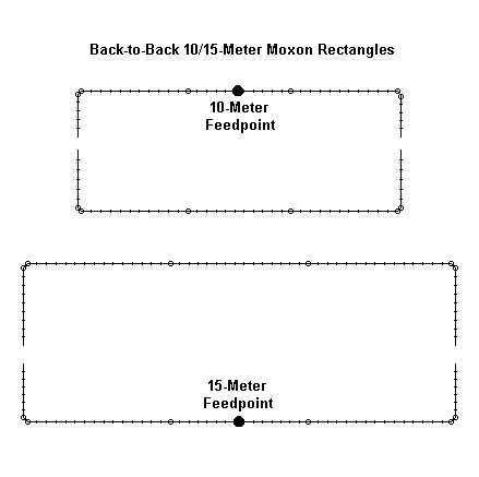
The overall boom length is about 12.7' with a little extra needed for element-to-boom mounting. The following table shows the values used in constructing the model:
10-15-meter Moxons back-to-back             Frequency = 21.225  MHz.

Wire Loss: Aluminum -- Resistivity = 4E-08 ohm-m, Rel. Perm. = 1

              --------------- WIRES ---------------
Wire Conn.--- End 1 (x,y,z : ft)  Conn.--- End 2 (x,y,z : ft)  Dia(in) Segs
1         -8.417, -4.930,  0.000  W2E1  -8.417, -7.007,  0.000 1.01E+00   7
2   W1E2  -8.417, -7.007,  0.000  W3E1  -8.249, -7.175,  0.000 1.17E+00   1
3   W2E2  -8.249, -7.175,  0.000  W4E1  -2.685, -7.175,  0.000 1.01E+00  15
4   W3E2  -2.685, -7.175,  0.000  W5E1   2.685, -7.175,  0.000 1.17E+00  15
5   W4E2   2.685, -7.175,  0.000  W6E1   8.249, -7.175,  0.000 1.01E+00  15
6   W5E2   8.249, -7.175,  0.000  W7E1   8.417, -7.007,  0.000 1.17E+00   1
7   W6E2   8.417, -7.007,  0.000         8.417, -4.920,  0.000 1.01E+00   7
8         -8.417, -4.222,  0.000  W9E1  -8.417, -1.168,  0.000 1.01E+00   9
9   W8E2  -8.417, -1.168,  0.000 W10E1  -8.249, -1.000,  0.000 1.17E+00   1
10  W9E2  -8.249, -1.000,  0.000 W11E1  -2.685, -1.000,  0.000 1.01E+00  15
11 W10E2  -2.685, -1.000,  0.000 W12E1   2.685, -1.000,  0.000 1.17E+00  15
12 W11E2   2.685, -1.000,  0.000 W13E1   8.249, -1.000,  0.000 1.01E+00  15
13 W12E2   8.249, -1.000,  0.000 W14E1   8.417, -1.168,  0.000 1.17E+00   1
14 W13E2   8.417, -1.168,  0.000         8.417, -4.222,  0.000 1.01E+00   9
15        -6.270,  3.920,  0.000 W16E1  -6.270,  5.575,  0.000 7.50E-01   5
16 W15E2  -6.270,  5.575,  0.000 W17E1  -6.145,  5.700,  0.000 8.75E-01   1
17 W16E2  -6.145,  5.700,  0.000 W18E1  -2.000,  5.700,  0.000 7.50E-01  11
18 W17E2  -2.000,  5.700,  0.000 W19E1   2.000,  5.700,  0.000 8.75E-01  11
19 W18E2   2.000,  5.700,  0.000 W20E1   6.145,  5.700,  0.000 7.50E-01  11
20 W19E2   6.145,  5.700,  0.000 W21E1   6.270,  5.475,  0.000 8.75E-01   1
21 W20E2   6.270,  5.475,  0.000         6.270,  3.920,  0.000 7.50E-01   5
22        -6.270,  3.400,  0.000 W23E1  -6.270,  1.125,  0.000 7.50E-01   6
23 W22E2  -6.270,  1.125,  0.000 W24E1  -6.145,  1.000,  0.000 8.75E-01   1
24 W23E2  -6.145,  1.000,  0.000 W25E1  -2.000,  1.000,  0.000 7.50E-01  11
25 W24E2  -2.000,  1.000,  0.000 W26E1   2.000,  1.000,  0.000 8.75E-01  11
26 W25E2   2.000,  1.000,  0.000 W27E1   6.145,  1.000,  0.000 7.50E-01  11
27 W26E2   6.145,  1.000,  0.000 W28E1   6.270,  1.125,  0.000 8.75E-01   1
28 W27E2   6.270,  1.125,  0.000         6.270,  3.400,  0.000 7.50E-01   6

              -------------- SOURCES --------------
Source    Wire      Wire #/Pct From End 1    Ampl.(V, A)  Phase(Deg.)  Type
          Seg.     Actual      (Specified)

1 (15 M)    8     4 / 50.00   (  4 / 50.00)      1.000       0.000       I
or
1 (10 M)    6    18 / 50.00   ( 18 / 50.00)      1.000       0.000       I

Ground type is Free Space
One slight peculiarity of this model is that the corners use a sloping wire to simulate tubing bends. However, in actual construction practice, this nicety of modeling has proven unnecessary: results with or without the corner sloping wire are well within the normal home shop construction variables.

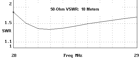
Performance on each band is quite normal. Fig. 2 shows the 50-Ohm VSWR curve for 15 meters, while Fig. 3 shows the 10-meter 50-Ohm VSWR curve. The slightly higher values of SWR across the band on 10 meters suggest that the 15-meter rectangle influences the 10-meter rectangle more than the other way around. As with monoband Moxon rectangles, forward gain varies from about 6.2 dBi at the low end of the band to about 5.7 dBi at the upper end in free space models. Relative to other 2-element designs, the front-to-back ratio is superior across the band.
I have received a number of notes wondering if parasitic elements might be added to a 20-meter Moxon to produce a triband beam. The addition of a 10- meter director and a 15-meter reflector yields some forward gain, but the feedpoint impedance makes large excursions, forbidding the use of coax.
These initial steps into developing a tri-band antenna around a 20-meter Moxon tend to stop short of something truly satisfactory. What is required for easy use is a system that permits a 50-Ohm feed for each band. The result will be more elements, but not a major increase in the footprint over and above the initial addition of a reflector and director.
To develop a beam of this order, one might well adapt some of the principles underlying the Force 12 C3. This popular antenna uses a 2-element 20 meter driver-reflector Yagi at its core. It also places a 15-meter driver-reflector combination behind the 20-meter driver. The two drivers are close enough to permit open-sleeve coupling. Ahead of the 20-meter driver are 3 10-meter elements--a driver (also open-sleeve coupled to the 20-meter driver) and two directors. The furthest director provides the essential pattern shaping function, while the closely-spaced first director functions much like the added director on the NW3Z/WA3FET OWA designs: it helps form a wider band feedpoint impedance than a single director could provide. Performance remains essentially the same as a 2-element driver-director Yagi, but over a larger portion of the band.
It is possible to replace the 20-meter elements with a Moxon rectangle and obtain tri-band performance on a 16' boom. Fig. 4 shows the general outline.
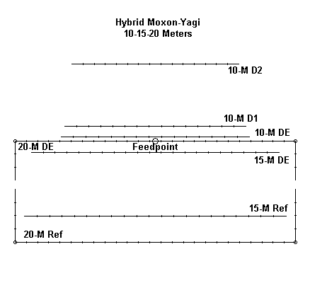
The following table presents some element data used in the models testing this idea. The elements are of uniform diameter for each band. Consequently, adjustments would be required for any element diameter tapering schedule used in an actual antenna. Likewise, none of the dimensions should be taken to be those of an actual C3.
Hybrid Moxon-Yagi                                 Frequency = 29  MHz.

Wire Loss: Aluminum -- Resistivity = 4E-08 ohm-m, Rel. Perm. = 1

              --------------- WIRES ---------------
Wire Conn.--- End 1 (x,y,z : in)  Conn.--- End 2 (x,y,z : in)  Dia(in) Segs

1        -138.50, 11.750,  0.000       138.500, 11.750,  0.000 7.50E-01  21
2        -132.00, 96.750,  0.000       132.000, 96.750,  0.000 7.50E-01  21
3        -101.00,112.250,  0.000       101.000,112.250,  0.000 5.00E-01  15
4        -97.000,124.250,  0.000        97.000,124.250,  0.000 5.00E-01  15
5        -89.000,190.250,  0.000        89.000,190.250,  0.000 5.00E-01  15
6        -150.00, 66.000,  0.000  W7E1 -150.00,108.000,  0.000 1.00E+00   3
7   W6E2 -150.00,108.000,  0.000  W8E1 150.000,108.000,  0.000 1.00E+00  25
8   W7E2 150.000,108.000,  0.000       150.000, 66.000,  0.000 1.00E+00   3
9        -150.00, 56.400,  0.000 W10E1 -150.00,  0.000,  0.000 1.00E+00   4
10  W9E2 -150.00,  0.000,  0.000 W11E1 150.000,  0.000,  0.000 1.00E+00  25
11 W10E2 150.000,  0.000,  0.000       150.000, 56.400,  0.000 1.00E+00   4

              -------------- SOURCES --------------
Source    Wire      Wire #/Pct From End 1    Ampl.(V, A)  Phase(Deg.)  Type
          Seg.     Actual      (Specified)

1          13     7 / 50.00   (  7 / 50.00)      1.000       0.000       I

Ground type is Free Space
For this exercise, the 20-meter elements were set at 1" diameter, the 15- meter elements at 0.75" diameter, and the 10-meter elements at 0.5" diameter. Since the design uses open-sleeve coupling, a single feedpoint suffices for all bands.
Here is a band-by-band run-down of potential performance. These figures are generated on MININEC (AO 6.5), since the close spacing of the drivers produces excess gain estimates in NEC-2. The error is an especially large overestimation of gain on 10 meters. Hence, MININEC is the core of choice for this exercise.
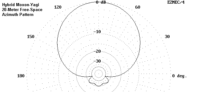
20 Meters: On 20 meters, the Moxon rectangle performs normally, with a typical Moxon pattern, as shown in the free-space azimuth pattern in Fig. 5.
The following table summarizes the performance across the band.
Freq.     F-S Gain        F-B           Feed Z         50-Ohm
MHz       dBi             dB            R+/-jX         VSWR
14.0      6.46            15.6          38-15          1.55
14.175    6.09            32.4          55- 6          1.15
14.35     5.72            21.0          69- 1          1.38
Fig. 6 demonstrates the anticipated SWR curve on 20 meters.

Relative to a Yagi driver-reflector combination, the Moxon shows a gain decrease of about 0.25 dB, but an increase in front-to-back ratio that exceeds 10 dB on average.
15 Meters: On 15, the pattern is that of a 2-element driver-reflector, as illustrated in the free-space azimuth pattern in Fig. 7.
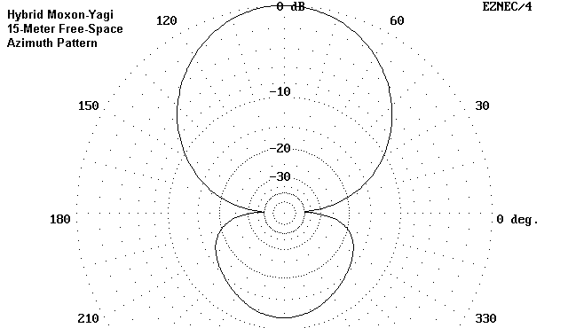
The modeled free space performance figures across 15 meters are these:
Freq.     F-S Gain        F-B           Feed Z         50-Ohm
MHz       dBi             dB            R+/-jX         VSWR
21.0      6.63           10.8           61-40          2.01
21.225    6.21           11.6           50+ 6          1.13
21.35     5.99           11.2           44+29          1.87
21.45     5.82           10.7           40+47          2.82
Note that the effective 2:1 SWR bandwidth is about 350 kHz or just a little bit more on 15 meters. One consequence of a simple open-sleeve coupling feed system is a more rapid rise in reactance as one moves away from resonance. At the upper end of the band, the reactance controls the SWR figure. One may, of course, reset the driver length to favor the upper end of the band. In addition, a broader operating bandwidth may exist at the ground end of a standard 50-Ohm coaxial cable--the exact width depending upon the line's length and losses.
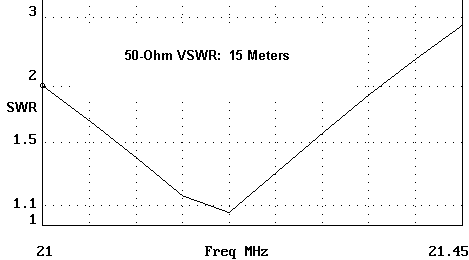
Fig. 8 shows in graphic form the SWR curve on 15 meters, as modeled in free space.
10-Meters: Fig. 9 shows a free-space azimuth pattern for the hybrid antenna at 28.5 MHz. Again, it is a typical 2-element Yagi pattern, with a slightly better front-to-back ratio due to the use of directors.
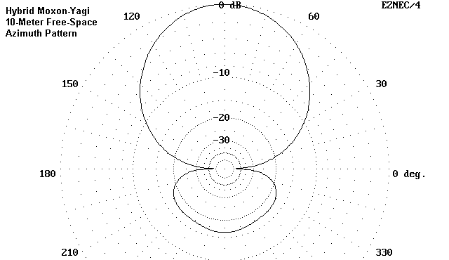
In tabular form, here are the AO predictions of performance, as referenced to free space.
Freq.     F-S Gain        F-B           Feed Z         50-Ohm
MHz       dBi             dB            R+/-jX         VSWR
28.0      6.31           15.0           57-37          2.00
28.5      6.59           16.4           46- 0          1.08
28.9      6.89           17.4           36+26          1.98
29.0      6.98           17.5           33+32          2.42
The gain and front-to-back ratio are typical for a 2-element driver- director design with one exception. The standard driver-director design has a narrow operating bandwidth for both the performance and the impedance characteristics. Something as narrow as 100 to 150 kHz is not unusual. The first director that is close to the driver provides the builder with the ability to tailor characteristics in a couple of ways. First, it forces the second director to a considerable distance from the driver so that characteristics change more slowly across the band. Second, it allows the builder to achieve a stable feedpoint impedance over much of the band--in this case, about 900 kHz between 2:1 SWR points, as illustrated in Fig. 10.
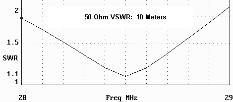
Undoubtedly, one can improve on this hybrid design. Indeed, the requirement for adjusting element lengths and spacings to account for element diameter taper schedules would enforce an exploration of possible improvements. As with all models of open-sleeve coupling, considerable adjustment may be needed in the slaved drivers to achieve the correct impedance and bandwidth. Moreover, although home construction of single antennas for personal use requires no special attention to any legalities, any other use of the non-Moxon-rectangle techniques noted in the design should involve consultation with Force 12 to ensure compliance with any proprietary or patent rights held by that company.
In both cases, the antennas use no loading devices, but instead employ full size elements. Any compacting of the overall size relative an antenna with only linear elements is a function of geometry. If I discover additional multi-banding techniques, I shall certainly add them to this note.
Updated 8-12-99. © L. B. Cebik, W4RNL. Data may be used for personal purposes, but may not be reproduced for publication in print or any other medium without permission of the author.