

The Moxon rectangle is a 2-element parasitical beam or unidirectional antenna about 70% the length of a full size 2-element Yagi of standard driver-reflector design. The rectangle, however, far exceeds other 2-element beams in front-to-back ratio, while almost equalling them in gain. This combination of properties is prized by those who adhere to the "good ears" theory of hamming.
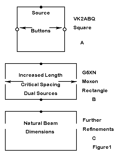
Les Moxon, G6XN, whose book HF Antennas for All Locations is now in its second edition, made two very significant discoveries about the Caton squares. First, a rectangular shape would improve gain. Second, the spacing between the ends of the wires is critical to proper antenna operation, and that spacing had to be greater than that provided by even the largest coat button. These significant improvements are noted in part B of Figure 1.
G6XN used a rectangle composed of two equal lengths of wire. However, he tuned each wire remotely from the shack, thus giving himself a fixed position reversible beam. He also developed a detuning addition to the elements to allow him to nest several bands' worth of rectangles.
My own work, aided considerably by the emergence of modeling software, has been devoted to refining and understanding the characteristics of the Moxon rectangle. To those ends, I developed the antenna as a uni-directional beam, allowing the elements to have their own native dimensions instead of electrically tuning them. This tack, shown in part C of Figure 1, led in turn to an understanding of why the antenna does what it does so well.
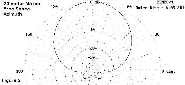
Figure 2 shows the free space azimuth pattern of a 20-meter all aluminum Moxon rectangle that we shall describe later on. At its design frequency, the antenna provides a forward lobe with a beamwidth so wide that it is nearly cardioidal. The forward gain is down from a full size 2-element Yagi only by about 0.2 dB. At the same time, the rear lobe is minuscule (compared to a front-to-back ratio of about 10- 12 dB as typical of a full size 2-element Yagi). The Moxon achieves this pattern without the use of a phasing line.
The combination of parasitical coupling from the parallel portions of the elements and the end coupling of the wires produces a current magnitude and phasing on the reflector element that is superior to that of many phased arrays in terms of effecting a rear null. Even the best ZL Specials and HB9CVs also leave quartering rear lobes that are often down by well under 20 dB. The Moxon's geometry, which includes the side wires or tails, tends to suppress those rear lobes, resulting in a very quiet rear quadrant.
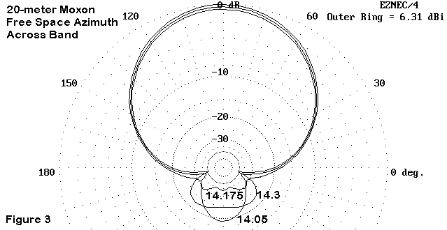
Although the most suppressed rearward pattern is frequency specific, the Moxon pattern holds up quite well across a ham band. Figure 3 shows the combined patterns for 14.05, 14.175, and 14.3 MHz for the example at hand. The gain changes by about 0.6 dB across the band, while the front-to-back ratio is still around 20 dB near the band edges.

Not only does the pattern hold up well, so too does the feedpoint impedance. The 20-meter model at hand was designed for a 50-Ohm feed-- which is a natural for the rectangle--and Figure 4 shows the 50-Ohm SWR curve across 20 meters. Coax feed--with a choke, of course--is the order of the day.
For tubing models, the Moxon corners can be a challenge. You can bend corner section of the next size larger or smaller tubing than the 1" size used in the 20-meter model. Or, you can try various fittings designed for other purposes, such as electrical conduit corners and the like.
The one critical factor is keeping the element ends in a fixed position relative to each other. I tend to use light-weight CPVC sections inserted into each aluminum tubing end, with sheet metal screws as simple position holders.
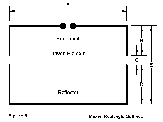
Figure 5 shows the operative dimensional parts of any Moxon rectangle. For the aluminum 20-meter Moxon, the length (A) is 25' and the overall width (E) is 9'. This yields a beam not much different than the size of a 2-element 15 meter antenna, but resonant on 20 meters.
The driver tail (B) is 3.5' long, while the reflector tail (D) is 4.7' long. The spacing between tail ends (C) is 0.8'. If you use tapered diameter elements or change the element diameters altogether, you should refigure the antenna with one of the antenna modeling programs.
For an interesting case study on the construction of a 20-meter Moxon rectangle, see "The Moxon Rectangle," by Morrison Hoyle, VK3BCY, in Radio and Communications (Australia), July, 1999, pp. 52-53.
Although I have published some numbers for wire Moxons before, here is a list of dimensions, using Figure 5 as a guide.
                  Table 1.  Moxon Dimensions for 40 - 10 Meters

Band     Design                      Dimension  (feet)
       Frequency (MHz)   A              B         C         D        E

10      28.50          12.44          1.94      0.41      2.41     4.76

12      24.94          14.22          2.22      0.46      2.76     5.44

15      21.20          16.72          2.63      0.52      3.25     6.40

17      18.12          19.56          3.10      0.59      3.80     7.49

20      14.17          25.00          4.00      0.72      4.85     9.57

30      10.12          35.00          5.60      1.00      6.80    13.40

40       7.15          49.56          8.01      1.33      9.63    18.97

Note:  all wire models composed of #14 copper wire.
All of the antennas exhibit feedpoint impedances between about 56 and 58 ohms at the design frequencies, a close match to the standard amateur 50-ohm coaxial cable. Free space gain and front-to-back ratio are consistent for all the models, averaging 5.8 dBi and greater than 32 dB in free space, respectively.
For a reversible direction wire Moxon rectangle with a stub-tuned reflector, see "Two-Element 40-Meter Switched Beam," by Carroll Allen, AA2NN, in The ARRL Antenna Compendium, Volume 6, pp. 23-25. The same volume also contains an expended treatment of the all-aluminum 10-meter Moxon that appears elsewhere in these pages.
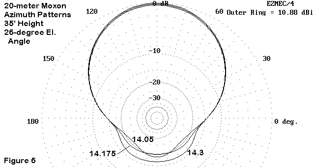
The pattern group at 35' up (1/2 wl) in Figure 6 shows that the antenna maintains quite usable forward gain and front-to-back ratio, although the rear patterns do not quite match the free space nulls.
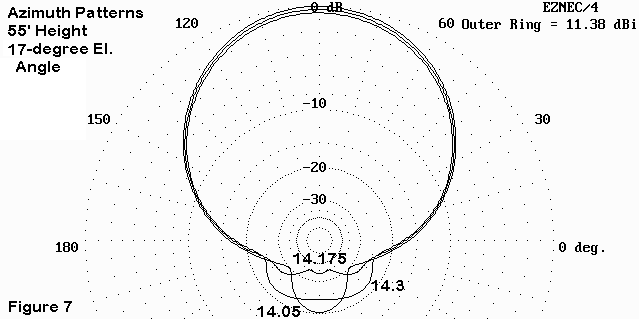
At 55' up (about 3/4 wl on 20 meters), Figure 7 shows that the rear lobes are almost non-existent at center band--and very good at the band edges.
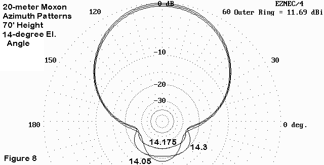
At 70' up (1 wl), the antenna shows a still different rear aspect, as revealed in Figure 8. At all three heights, the SWR curve does not depart significantly from the free space curve shown in Figure 4.
Tuning up a Moxon rectangle--or adjusting the dimensions for other materials--is straightforward. The length (A) tends to control the overall impedance. However, adjusting the driver tail (B) has the most immediate affect on feedpoint reactance. Adjusting the reflector tail (D) affects most the resistance at the feedpoint. The spacing (C) has the greatest affect upon the place of the deepest null within the ham band of choice. These guides assume that the antenna has been initially adjusted within some sort of ballpark specification set.
The wire dimensions use slightly longer tails and slightly closer spacing between tail ends than the tubing models to achieve roughly the same results and feedpoint impedances. Tubing models tend to show slightly (operationally insignificantly) higher gains (about 0.15 dB), as well as shallower SWR curves. However, a wire model for 20 meters would easily cover the band.
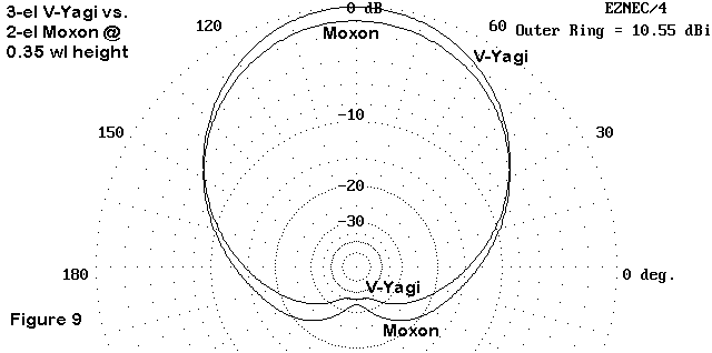
The principle also has application to 3-element design. The optimized 40-meter "V-Yagi, " (superficially resembling an older G4ZU design) by Nathan Miller, NW3Z, and Jim Breakall, WA3FET, in QST for May, 1998, has an azimuth pattern quite similar to those shown for the Moxon rectangle, but with the higher gain associated with three elements. See Figure 9. The wire director and reflector angle back toward the driven element, effecting some degree of end coupling while retaining parasitic characteristics.
Whether you call the antenna a VK2ABQ square, a Moxon rectangle or something else, the design is well worth considering if you want a compact beam about 0.35 wl long by 0.13 wl wide with a direct coax match. For those who desire more QRM rejection than raw gain, the design has much to offer.
For further reading, see the following:
"Modeling and Understanding Small Beams: Part 2: VK2ABQ Squares and Moxon Rectangles," Communications Quarterly (Spring, 1995), 55-70
"Moxon Rectangles for 40-10 Meters," QRPp (December, 1995), 25-27
Updated 12-18-99. © L. B. Cebik, W4RNL. A version of this item first appeared in AntenneX, Oct., 1998. Data may be used for personal purposes, but may not be reproduced for publication in print or any other medium without permission of the author.