

The growing interest in the Moxon Rectangle as a wire beam for 40-meter use has prompted me to collect some of my casual notes on the subject and place them here. The aim is to provide a few extra ideas for those wishing to experiment with the antenna.
We can divide the notes into two parts. The first will look at some alternative "wires" that we might use to build the 40-meter Moxon rectangle. WE shall discover that the choice of materials has some consequences worth noting.
The second part will discuss the potential of the Moxon Rectangle as a bi- directional wire beam, using a simple "switching" mechanism.

For convenience, I shall refer to dimension A as the "side-to-side length" and to dimension E as the "front-to-back width."
In another note in this series, I provided dimensions for a 40-meter Moxon Rectangle made from #14 wire and design to provide a reasonable match to 50-Ohm coaxial cable. That design was centered on the band center (in the U.S.) of 7.15 MHz. One consequence was that the design did not provide a 2:1 VSWR curve that covered the entire band.
By lowering the center frequency just a little, the VSWR objective can be attained without undue loss of operating properties at the upper end of the US 40-meter band.
#14      Design                      Dimension  (feet)
Cu     Frequency (MHz)   A              B         C         D        E

40       7.08          50.05          8.09      1.34      9.73    19.16
This revision was part of a larger group of models, the differences of which are summarized in Fig. 2.

I also experimented with a model of the antenna made from 2" diameter aluminum, again striving for a 50-Ohm feedpoint impedance with under 2:1 VSWR across the band. The resulting dimensions are as follows:
2.0"     Design                      Dimension  (feet)
Al     Frequency (MHz)   A              B         C         D        E

40       7.10          49.91          6.99      1.60      9.38    17.97
Note the shortening of dimension A, with the increase in element diameter. However, the major changes occur in dimensions B and C. The tail length of the driver is nearly 1' shorter than for the #14 version, and the required spacing for the element ends (dimension C) is about 2" greater. Remember that the most critical building dimension for the Moxon rectangle is the spacing of the element tails, so the 2-inch change may be more important than the larger tail length change. In all modes of construction, strive to make sure the element end spacing remains constant as the antenna moves in the wind.
The aluminum Moxon rectangle was a thought experiment, although a similar antenna, composed of a wire and tubing combination, is made commercially. A more practical version of the antenna might consist of simulated large diameter wire. The simulation consisted--for my modeling experiment--of two #14 wires spaced 3" (0.25') apart--a reasonable set-up for shop-made parallel transmission line and hence a possibility for the antenna structure. The wires come together at their ends. for the reflector, that means junctions at the element ends only. For the driver, junctions occur at the element ends and at the feedpoint. The dimensions that modeled within our design goals are these:
2x#14    Design                      Dimension  (feet)
Cu     Frequency (MHz)   A              B         C         D        E

40       7.10          49.59          6.28      2.26      9.68    18.22
Because two parallel wires do not act in exactly the same way as a single fat wire, changes occurred in all dimensions. With respect to the front- to-back width, the driver tails grew shorter and the spacing larger. However, the reflector tails also grew, relative to the aluminum model.
Now for some interesting results, which I have graphed from frequency sweeps of the three antennas across the US 40-meter band. The figures are for free space, but the Moxon rectangle translates these very reliably into performance at any chosen height above the ground. See some of the other notes in this collection for changes of pattern that occur as we move from free space to realistic antenna placement heights.
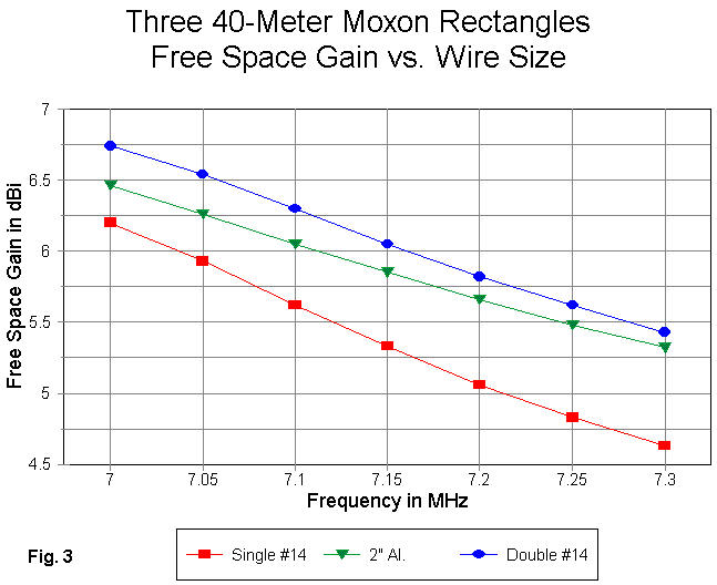
Fig. 3 provides comparative gain curves for the three versions of the antenna. Note that the single #14 wire version has the steepest curve. The 2" aluminum model has the shallowest curve, even shallower than the higher gain double #14 version. This further shows that while a double wire is a useful simulation of a single fat wire, it is not an exact replacement.
The gain progression from the single #14 wire to the 3"-spaced pair is clear. Whether the gain increase is worth the added complexity or weight of construction is a builder option.
More significant are some interesting facts about the rectangle. Although the geometry is not closed, the Moxon shares a property in common with the single quad loop (and beams composed of multiple quad loops). Wire versions are relatively inefficient. Almost any antenna design has a minimum diameter (and consequential surface area) for the efficiency to approach or surpass 99%. #14 wire is too small to achieve this figure in the Moxon rectangle, since the single wire model reports a 95.3% efficiency. The 2" elements of the aluminum are more efficient, despite the increased resistivity of aluminum compared to copper. The NEC report was 99.7% efficiency. Part of the improved gain of the aluminum model undoubtedly comes from the improved efficiency.
Part--but not all. Remember that the design goal was to retain something close to a 50-Ohm feedpoint impedance. The dimensions changed in every respect, and those changes also play a role in spacing the parallel portions of the elements and in spacing the element ends to yield better gain. The evidence for this comes from the reported figures for the double-wire #14 version of the antenna: the gain is systematically higher, but the efficiency is only 96.8%, well under that of the aluminum beam and not much higher than that of the single-wire #14 model.
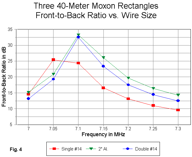
The 180-degree front-to-back curves in Fig. 4 show a tight coincidence between the two "fat-wire" version of the antenna. The single-wire #14 version also has a peak front-to-back value that comes close to those of the other two models. However, it occurs at about 7.07 MHz. If we arbitrarily place a point at that frequency in the neighborhood of 32 dB, we would immediately see that the "thin-wire" version of the antenna has a much steeper curve than the other two models.
In this case, effective wire thickness has a direct bearing on the broadness of the front-to-back characteristic of the rectangle. The double wire does not quite match the values across that band that are achieved by the aluminum model, but the differences are relatively insignificant. Compared to either "fat-wire" model, the single-wire #14 version is extremely thin--and that takes it toll on the front-to-back ratio-- especially at the upper end of the band. For those with narrower 40-meter windows, the difference might not make any difference at all.
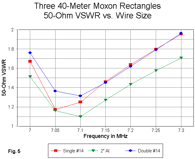
The VSWR curves in Fig. 5 show that any of the antennas would provide a 2:1 operating bandwidth that covers the entire band. Since the single wire center design frequency is below 7.1 MHz, its lowest SWR value does not show. The double-wire version of the antenna was optimized only to the point of providing a 50-Ohm SWR under 2:1 at the band edges. Further tweaking would drop its curve lower, but at no essential gain in any other operating parameter.
Greater dimensional changes are likely to occur as a result of adopting one of the recommendations often made for double-wire or cage construction. To keep the current the same in each wire at any length along the antenna, some builder use periodic shorting wires across the two wires. The effects on the dimensions of this practice have not yet been modeled.
An additional builder option may also occasion a change in the listed dimensions, especially in the spacing of the element ends. The model developed for this exercise used "blunt" ends, that is, wires brought to parallel points with a shorting wire across them. If the builder brings the element tails to a point, the coupling between the driver and reflector element ends will be reduced, very likely requiring that the space between ends be closed somewhat.
Whatever, the variables, these three versions of the 40-meter Moxon rectangle provide some insight into the operation of the antenna. They also offer some challenges to the builder in getting the most out of the array.
In other notes on lower HF wire beams, I introduced two designs by AA2NN-- one for a bi-directional Yagi, the other for a bi-directional Moxon. These notes deserve some repetition and embellishment here, since fixed wire beams often earn their space by working in two directions.
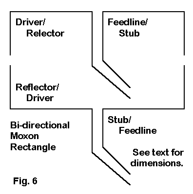
Fig. 6 notes the basic features of a bi-directional Moxon. Each element is cut as a driver and hence are identical. The feedline chosen as the driver line acts as simply another section of the main feedline. The feedline section selected as the reflector line is a stub that electrically loads the element to proper reflector length. Like all of the rectangles in this note, the design frequency was low in the band to provide operating coverage over the full 300 kHz spread. The dimensions of the design considered here are as follows:
#14      Design                      Dimension  (feet)
Cu     Frequency (MHz)   A              B         C         D        E

40       7.08          50.05          8.09      1.34      8.09    17.52
If you compare the design to the single-wire #14 copper rectangle, you will see that the driver has not changed, but the reflector has been shrunk to match the driver. The spacing between element remains as before.
The result is a design centered on the CW end of 40 meters. The AA2NN design uses different dimensions to center the design in the U.S. phone portion of the band. Interestingly, despite seemingly significant differences in the dimensions, the required stub lengths to load the reflector are within 1 degree of each other.
The inductive loading reactance required to restore the array to peak performance at the design frequency is about 73 Ohms (subject to variations according to the circumstances of installation). An equivalent shorted stub of 50 Ohm coax is 55.6 degrees long--or 21.45' if the velocity factor (VF) were 1.00. (Simply multiply this length times the velocity factor of your own coax to get the final length.) If a much longer line is needed to reach a ground-mounted central remote switch, you can add 180 degrees (1/2 wl) to this figure. If an intermediate length is required, you can use an open-ended stub that is 145.6 degrees long--or 56.18 feet at a VF of 1.00. Techniques for calculating the length of stub lines from the required reactance appear in most antenna manuals.
Expect losses from the stubs. The longer the stub the higher the loss. For most parasitic arrays, reflector stub losses result in slightly reduced gain, but may actually increase the front-to-back figures relative to modeled ideals. The switch or relay converting the stub from and to part of the transmission line system should be DPDT. In stub use, the center conductor and the braid of the stub should be independent of the center conductor and braid of the main feedline, whether used in a shorted or open configuration.
Let's compare the performance of the bi-directional #14 copper Moxon with the one-way counterpart.
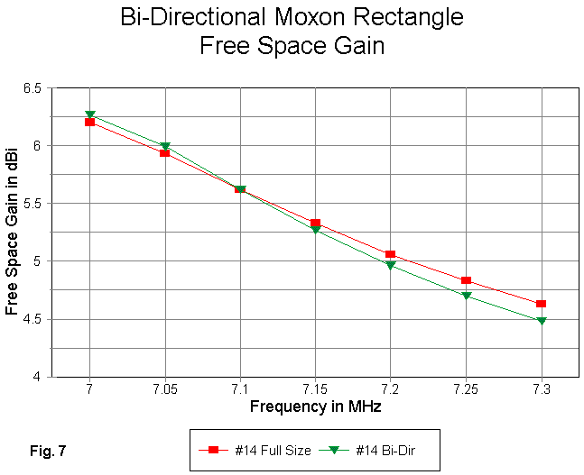
In Fig. 7, we can see that the gain curve of the bi-directional model is slightly steeper than the curve of the one-way model. Loading the reflector yields slightly different relative current magnitudes and phases on the elements at all but one frequency. However, the differential is not operationally significant.
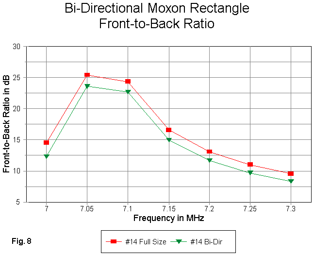
In Fig. 8, we can see the effects of using a loaded reflector. The front- to-back curves of the two antennas are almost perfectly parallel. However, the bi-directional model shows a lower front-to-back ratio, partly due to the closer spacing of the horizontal wires that results from loading and element that is only as long as the normal driven element. To this front-to-back figure, one must add the effects of stub losses, which are not accounted for in the model. The operational difference from the model will be insignificant compared to differences created by the circumstances of installation.
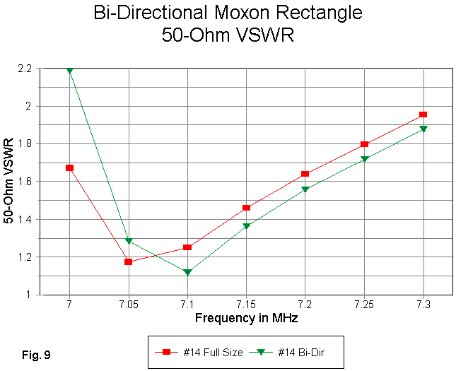
Fig. 9 shows comparative 50-Ohm VSWR curves. With a bit of further dimensional juggling, the curve for the bi-directional model can be brought within 2:1 values for both band edges. However, the curve given is sufficient to note that the bi-directional model displays somewhat sharper tuning than the one-way version. With a load in the reflector element, the reactance tends to increase more rapidly across the band.
Nonetheless, the bi-directional Moxon rectangle can be designed to provide full band coverage of 40 meters--or to be focused in one favorite segment of the band. There is no significant performance degradation except for a little of the front-to-back ratio. I have not carried out any bi- directional modeling exercises using the double-wire model, but it should perform within similar limits relative to its one-way version.
As a monoband array, the Moxon rectangle remains one of the most flexible compact wire beams around. I hope these notes encourage further experimentation with the design. Many untouched possibilities remain to be discovered.
Updated 5-4-99. © L. B. Cebik, W4RNL. Data may be used for personal purposes, but may not be reproduced for publication in print or any other medium without permission of the author.