MODELING AND UNDERSTANDING SMALL BEAMS
PART 4: LINEAR-LOADED YAGIS
The most common reason for designing and building a small, 2-element beam or array is the size. Whether for home or portable field use, small antennas have a niche in the ham world.
There is a second, often overlooked reason for building antennas with reduced dimensions relative to a standard 2-element Yagi: increased front-to-back ratio. Standard, closed spaced (approximately 1/8) Yagis are not capable of large front-to-back ratios because the parasitic reflector will not be positioned or sized to have the correct current level and phase angle for maximum rejection off the rear. Most notably, the Moxon rectangle achieves close to optimal reflector conditions. Its altered geometry attains a very high front-to-back ratio for a 2-element array. The cost is about a half dB of forward gain.
A second strategy that will also improve the front-to-back ratio is to shorten the Yagi elements while maintaining the close spacing. With center- or linear-loading of both the driven element and the reflector of a 2-element Yagi with about 1/8 spacing, the front-to-back ratio increases from about 12 dB to about 18 dB, a full S-unit of improvement. Models of the beam show that the current amplitude and phase more closely approach values necessary for a complete rearward null than those for a full size 2-element Yagi. As with the Moxon rectangle, the short beam's forward gain drops about a half dB in the process. Additionally, the bandwidth of the beam decreases.
The result of modeling and testing these ideas was a 2-element 10-meter Yagi with 12' elements, which is a 25% savings in size, turning radius, and weight. In addition, the antenna uses 6' lengths of hardware store aluminum tubing for the elements, making parts acquisition easier. (Note, however, that the aluminum tubing usually available at hardware centers does not have the strength and durability of tubing used by commercial antenna manufacturers. This factor has little affect on small, weight-balanced 2-element beams for 10 meters, but may be very significant in tapered-element 20-meter models.1)
The principle of center loading is very old and well-understood. A coil at the center of a shortened inductor compensates for the capacitive reactance that results from shortening the element from its naturally resonant length (approximately 1/2), thus restoring resonance. A parasitic element, such as a reflector may be similarly shortened and use an inductor to compensate for the resultant capacitive reactance until its relationship to the driven element is as optimal as possible. Center-loaded dipoles and Yagis have appeared in numerous antenna books over the decades.
The performance of a center-load dipole or Yagi depends largely upon the Q of the inductor. A shortened antenna, solely by virtue of its shortening, will show a reduction in gain relative to an unshortened antenna used as the reference. We might let a center-loaded dipole or Yagi use theoretic inductors with infinite Q (that is, with no resistance) to form a base line for comparisons. Then, by selectively establishing values of Q for the inductors and modeling the result (via a program such as MININEC), some rough comparisons become possible.
                        A Comparison of Gain and Other Properties of Center-Loaded
                                    and Linear-Loaded Dipoles and Yagis

1/2 wl Dipole: 12' 0.75" diameter aluminum

Type           QLoad           Gain             Impedance
                                dBi              R±jX
C-L             Inf.            1.93            28 + 0.4
C-L              50             1.24            33 + 0.5
C-L             100             1.57            31 + 0.5
C-L             200             1.75            30 + 0.5
C-L             300             1.81            29 + 0.5
L-L             ---             1.82            29 + 0.3

2-Element Yagi:  DE = 11.6' 0.75" diameter aluminum; RE = 12' 0.75" diameter aluminum

Type           QLoad           Gain             Front-to-Back                   Impedance
                                dBi              Ratio dB                         R±jX
C-L             Inf.            6.20             20.0                           17 - 0.7
C-L              50             4.21             13.2                           22 - 3.9
C-L             100             5.14             15.8                           19 - 2.4
C-L             200             5.65             17.6                           18 - 1.6
C-L             300             5.83             18.3                           18 - 1.3
L-L             ---             5.82             18.4                           17 - 2.8
C-L            DE=200           5.02             13.2                           19 - 3.9
               RE= 50
C-L            DE= 50           4.84             17.6                           22 - 1.6
               RE=200

Notes:  C-L = center-loaded; L-L = linear-loaded.  All values taken from models in free space and
include materials losses (aluminum).  As an indicator of loading coil losses, QLoad=XL/RL.  XL for
DE=250 Ohms; for RE=257 Ohms.  Antennas L-L are linear-load with a 4' loading element of #12 wire in a
vertical plane, with the upper wire 1.2" below the main element and the lower wire 1.2" below the upper
wire.

Table 1.  A comparison of gain and other properties of center-load and liner-loaded dipoles and Yagis.
Table 1 summarizes two such exercises, one for 12' aluminum dipoles at 28.5 MHz, the other for a 2-element Yagi of similar element length at the same frequency. The table shows Qs of 300, 200, 100, and 50 as typically realizable values, although sustaining an inductor at a Q of 200 or more in outdoor conditions is unlikely. A Q of 100 is more likely. Note the decrease in performance with the decrease in Q for both the dipole and the Yagi.

A linear load is simply a folded continuation of the main element, usually (but not necessarily) of a lighter (hence, thinner) material, as shown in the dipole sketch in Fig. 1. Linear loading can be introduced anywhere along an antenna element, including current and voltage maxima points, but we shall restrict our focus here to current nodes, that is, to the center point of 1/2 elements. Although there are numerous reports of empirically generated antennas using linear loading, little has been quantified in amateur literature.2 As a start toward this goal one may juxtapose linear-loaded dipoles and Yagis with their center-loaded counterparts. For comparison with the center-load models of both dipoles and Yagis in Table 1, I added a linear-load model with #12 wire extending 2' either side of the element center in a vertical plane below the main element. The upper wire is 1.2" below the main element, and the lower wire is 1.2" below the upper wire.
A model of the linear-loading element is only approximately comparable to the model of the center-loaded element because of differences in modeling conventions. A loading inductor (or capacitor) is treated in both NEC and MININEC as a nonradiating item inserted into the structure. By contrast, the linear-loading structure is part of the overall radiating structure of the antenna. Moreover, since most versions of MININEC permit but one material, the models are all-aluminum, even though in practice the linear-load element will usually be copper. Nevertheless, figures for the linear-loaded model given in Table 1 are roughly comparable with the center-loaded results and indicative of relative performance. In both cases, the material losses of the main aluminum element are included in the model.
Whether a dipole or a Yagi, the gain of linear-loaded elements tends to surpass that of the corresponding center-loaded elements by a significant amount. So, too, does the front-to-back ratio of the Yagi model. If we assume that a Q of 100 is a reasonable and sustainable figure for a center-loading inductor, then linear loading becomes a very attractive alternative in shortened horizontal antennas. It generally requires a center-loading coil Q of 300 or better to reach the performance of a linear-loaded Yagi.
The last two entries under the Yagis in Table 1 are included to demonstrate the effects of losses should only one of the Yagi's two elements exhibit more than design losses, perhaps due to weathering. Reduction of reflector Q results in a lower front-to-back ratio and a higher reactive component to the feedpoint impedance. In contrast, reduction of the driven element Q results in a lower antenna gain and a higher resistive component of the antenna feedpoint impedance. Understanding these differences can be an aid to trouble shooting antenna problems.
The resemblance of a centered linear-loading element to a transmission line is no accident. In fact, each half of the linear-loading element can be viewed as a shorted, inductive transmission line stub, and this view provides a basis for approximate calculations of the element length. Each half of the element represent a reactance, and the two halves are in series.
The designer can derive the required total reactance of a shortened dipole by simply using MININEC or NEC to model the short element at the desired frequency. Alternatively, one can measure the feedpoint impedance of an actual main element without loading. The capacitive reactance at the feedpoint requires exact compensation by an equal inductive reactance provided by either a center loading coil or, as here, a shorted length of transmission line.
Materials for a linear-loading element are a matter of designer preference within the limits of good structure. Given the selection of wire, rod, or tubing for the linear load, the process of calculating the linear load begins by determining the characteristic impedance, Zo, of the proposed load line, using the standard approximation,

where S is the spacing between the wire centers and d is the wire diameter, both in the same units.3
From the value of Zo and the desired reactance, determine the line length in electrical degrees, LE, from the equation,

where XL is the total desired reactance. The doubling of Zo in the denominator provides for the length of each half of the linear loading element. Converting the length into feet requires the design frequency, FR, the assumption of a velocity factor of 1, and the equation

Remember to double the length for the full element.
The utility of this calculation procedure is limited. There are two generally popular geometries for constructing linear-loaded center elements. Fig. 2 compares the "end-on" appearance of vertical-plane geometry with triangular geometry. Because the load lines of the triangular arrangement are usually equi-spaced from the main element, the transmission-line calculation produces useable results as a first approximation for building. However, the vertical-plane geometry places one "side" of the transmission line closer to the main element, thus disrupting the presumed equal currents and voltages essential to the calculation's accuracy.
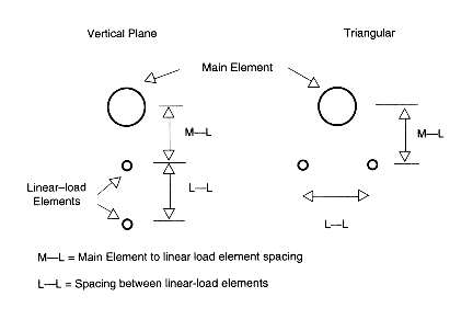
Calculations of triangular linear load elements correspond in the main with models of fully structured antennas within about 2 to 3 percent. Because of limitations in modeling linear-loaded antenna structures, the calculations are as good as the model as a guide to building.4 However, transmission-line calculations vary from modeling results for vertical-plane antennas by 15 to 30 percent, depending upon the particular line size and spacing. The calculations tend to call for radically shorter linear load elements than actually needed. To get a handle on vertical-plane linear loading arrangements requires a different technique.
A standard Yagi element or a dipole antenna shows a set of currents that decrease continuously but not linearly from the feedpoint, since the elements are roughly resonant. An element with a linear-loading element has an overall wire length (counting both the element tube and the load wire) that is longer than a half wavelength. Hence, the current rises as one moves away from the feedpoint, reaching a secondary maximum over halfway out the loading element and reaching a primary maximum on the way back in toward the junction with the tube. The inequality of currents in the outgoing and incoming wires of a vertical-plane linear-loading element verifies that the loading element is not acting as a pure transmission-line element. The current along the element does not rise much and the tube-to-load element junction shows over 99% of the current. Essentially, the radiation produced by the currents in the loading element cancel, leaving the tube element radiation to dominate the far field pattern. Cancellation is not perfect, thus leaving a high current level over a greater length of the antenna element than with lower-Q center loading schemes.
Correlating models of linear-loaded dipoles with center-loaded counterparts permits a rudimentary calibration of linear-loaded dipole of both vertical-plane and triangular geometries. Free space models of fixed-length main elements with variable linear loads were checked for resonant frequency as indicated by a near-zero reactance. Then, using the same frequency, an equivalently long dipole of the same material was center loaded to resonance by the same test. The requisite reactance became the center-load lossless-inductor reactance for the linear load. Flipping between copper and aluminum elements (both tubing and linear-load wire) produced no change in the resonant point. As noted above, the modeling process is subject to certain limitations of both MININEC and NEC.
             Sample table of linear-loaded dipoles listing gain, feedpoint impedance, resonant
                      frequency, equivalent center-load reactance, and approximate Q

                               Antenna element = 12' 0.75" diameter aluminum
       Linear load = #12 wires spaced 2" (0.167') from antenna element; 2" (0.167') from each other
                             Antenna-to-linear load geometry:  vertical plane

Linear load    Gain            Z (R±jX)       Resonant        Equivalent            Approximate
length - ft     dBi             Ohms          Frequency      Center-load             equivalent
                                                 MHz          Reactance                  Q
                                                                 Ohms

0 (self-        2.13       72.2 + 0.01         38.94           -----                  -----
resonance)
1               2.01       49.4 + 0.00         35.04            85.4                   225
2               1.94       37.4 - 0.02         31.84           157.7                   303
3               1.85       29.6 - 0.00         29.34           217.4                   294
4               1.78       24.4 - 0.01         27.12           273.9                   326
5               1.69       20.7 - 0.00         25.20           327.2                   327
6               1.60       18.0 - 0.02         23.58           375.8                   334

Notes:
1.  Antennas were considered resonant if the remnant reactance was less than 0.05 Ohm.  Figures are
rounded from 3- and 4-place decimal results.
2.  Equivalent Q is determined by finding a value of resistance for the center load inductance at the
given reactance that produces an antenna gain equal to that of the corresponding linear-loaded model.
Q results are subject to variables of the modeling process and are likely no more reliable than 10 to
15 percent.

Table 2.  Sample table of linear-loaded dipoles listing gain, feedpoint impedance, resonant
        frequency, equivalent center-load reactance, and approximate Q.
Table 2 provides a sample of the data developed for just one linear-load configuration: a vertical-plane arrangement with a #12 wire spaced about 2" from the main element and 2" apart for a 12' element. The table clearly shows the decrease of gain as the linear element is lengthened, along with the increase in equivalent reactance and the decrease in resonant frequency. Since the goal was to develop dimension figures adequate to the start of home construction, resonance was defined as a remnant feedpoint reactance of less than 0.05.
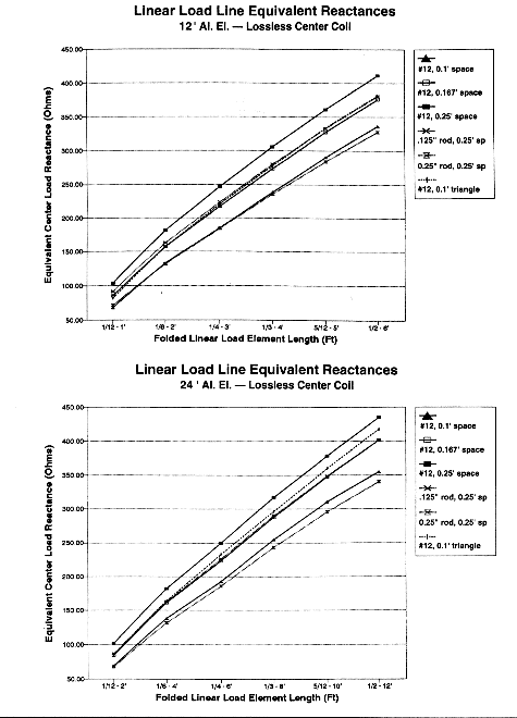
Fig. 3a and 3b show the results of six dual runs on linear elements (1/2 dipoles) of different lengths, materials, and spacing. Each type of element shows a reasonably linear increase in equivalent reactance with increases in length. (Note that the element length is for the folded element; the actual wire length is twice that amount plus connecting leads.) Extrapolation to intermediate lengths and similar but deviant linear-load configurations is possible for other required values of reactance.
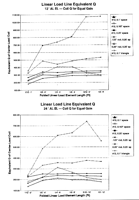
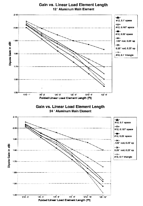
Although the equivalent reactance was derived using zero-loss center-loading inductors, an indication of equivalent Q was derived by adding resistance to the inductor until the antenna gain was the same as the linear-loaded model. Table 3 provides the data on equivalent Q-ranges for the linear-load geometries shown in the graphs in Fig. 4a and 4b, with specific data on gain and Q for one typical linear section length. Fig. 5a and 5b provide gain profiles for 6 variations each using 12' and 24' 0.75" diameter aluminum main elements.
                    A comparison of linear-loaded dipoles listing geometry, materials,
               Q range (for all load lengths), and gain and Q (with a 4' or 8' load length)

Antenna        Geometry &              Range of Q               Gain with               Q with
   #            Materials             (1-6' length)          4' linear section      4' linear section

                      Antenna element = 12' 0.75" diameter aluminum; load length = 4'

   1           VP, 0.25" rod            1075-355                  1.90                   812
               sp: 0.25'/0.25'
   2           VP, 0.125" rod            532-328                  1.82                   487
               sp: 0.25'/0.25'
   3           VP, #12 wire              355-267                  1.74                   343
               sp: 0.25'/0.25'
   4           VP, #12 wire              334-224                  1.78                   326
               sp: 0.167'/0.167'
   5           VP, #12 wire              293-183                  1.82                   293
               sp: 0.1'/0.1'
   6           Tri, #12 wire             411-233                  1.80                   411
               sp: 0.1'/0.1'

Antenna        Geometry &              Range of Q               Gain with               Q with
   #            Materials             (1-12' length)         8' linear section      8' linear section

                      Antenna element = 24' 0.75" diameter aluminum; load length = 8'

   1           VP, 0.25" rod             739-600                  1.91                   632
               sp: 0.25'/0.25'
   2           VP, 0.125" rod            375-229                  1.81                   352
               sp: 0.25'/0.25'
   3           VP, #12 wire              256-225                  1.72                   256
               sp: 0.25'/0.25'
   4           VP, #12 wire              238-168                  1.75                   232
               sp: 0.167'/0.167'
   5           VP, #12 wire              213-138                  1.77                   196
               sp: 0.1'/0.1'
   6           Tri, #12 wire             313-185                  1.76                   266
               sp: 0.1'/0.1'

Note:  VP = linear load elements in vertical plane with antenna element; Tri = linear elements in triangular
        configuration with antenna element.

Table 3.  A comparison of linear-loaded dipoles listing geometry, materials, Q range (for all load lengths), and
        gain and Q (with a 4' or 8' load length).
Triangular geometry loads do not fully overlap their vertical-plane counterparts. As shown in Fig. 3a and 3b, the close-spaced triangular arrangement of #12 wire turns out to parallel closely the reactance progression of vertically planed #12 wire spaced more widely (0.167' vs. 0.1') or 1/8" rod spaced at 0.125'. However, the equivalent Q of the triangular configuration shows a clear peak at midlength load element sizes, as shown in Fig. 4a and 4b. In common with the vertical plane #12 linear-load configuration, the #12 triangular configuration shows a more rapid fall-off in gain after the 4' point with 12' main elements and after the 6' point with 24' main elements. See Fig. 5a and 5b. The rapid reduction in gain for close-spaced #12 linear-load elements suggests that the break points on the graph represent the limit of their effective use compared to other configurations.
Besides the linear relationship between element length and equivalent center-loaded lossless-inductor reactance, certain other trends in Fig. 3, 4, and 5 are noteworthy:
1. Spacing: For a given geometry, load-length, and wire size, antenna element gain decreases and Q increases as spacing increases.
2. Wire size: For a given geometry, load-length, and spacing, antenna element gain and Q increase as the wire size increases.
3. Geometry: For a given load-length, spacing, and wire size, a triangular geometry yields a higher Q than the vertical-plane geometry, but provides less antenna element gain.
4. Diameter: As main element and linear section wire diameters decrease relative to a wavelength at the signal frequency, reactance increases slowly and Q decreases.
5. Long linear elements: As the ratio of linear-load length to main element length exceeds 5:12, both the equivalent center-load reactance and Q tend to depart from a relatively linear curve. Note that, although the Q curves for 0.125" and 0.25" diameter linear-load elements seem to depart radically from the #12 vertical-plane models, a closer examination of the curves show that they are topographically similar, with a fairly complex magnitude adjustment factor.
6. Short linear elements: As the ratio of linear-load length to main element length falls below 1:6, both the equivalent center-load reactance and Q tend to depart from a linear curve, with the Q falling off rapidly.
7. Recommended linear element lengths: Between ratios of 1:6 and 5:12 of the linear-load element to the main element, equivalent reactance and Q curves are nearly linear, as is the rate of decrease in antenna element gain with increased linear-load length. As noted, close-spaced #12 linear-load elements depart from this near-linearity of gain and Q beyond certain "break" points, which limit their applicability.
One further trend also deserves notice: the longer the loading element (or the higher the reactance of any center-loading means), the lower the resistive feedpoint impedance. Linear-loading elements in the vicinity of one-third the total length of the main element show a resistive component between 20 and 30 , depending upon design. A direct match to 50- coaxial cable is accordingly not feasible, although simple beta, gamma, balun, and transformer matching systems are available. For anyone concerned about the small mismatch that exists between a full size dipole (72 nominal) and 50- coax, a short linear load of 1/12 the main element length is a solution. The result is, in almost any construction mode, a feedpoint impedance within ±5 of the coaxial cable's Zo. Of course, the main element will have to be shortened from full size, but the decreased size produces negligible gain loss (less than 0.1 dB).
For shortened Yagi designs or portable field dipoles, a close-spaced linear element approximately 1/3rd the length of the main element represents a good compromise among a number of factors to consider when designing a shortened antenna. It maintains element gain at a high level, while effecting a significant shortening of the overall element length. Specific design objectives, of course, may require a departure from these very general recommendations.
The linear-loading section curves developed for 12' and 24' main elements can be used directly for 10- and 20-meter beams by extrapolation. Extrapolations for other bands will be less precise, but sufficient for reasonable construction estimates. A recommended alternative is to create a set of curves for the specific materials to be used in a given project. With almost any antenna modeling program, the task is an evening's work. In the end, no matter how extensive the modeling, home construction techniques will rarely be exact enough with respect to replicating the modeled spacing among the parts of a linear-loaded element to permit building without adjustment. However, the tables and graphs do provide some initial quantitative guidance. For those who prefer to use the transmission-line stub calculations as a foundation for building, Table 4 provides a set of generalized deviance factors for correcting the calculations to correspond with each of the types of linear loads described here. The averaged factor holds for linear-load lengths between about 15 and 40 percent of the main element length. The progressions of correction factors may also serve as a guide to builders using load dimensions outside the range of those analyzed here.
                        Correction Factors for Using Transmission Line Calculations
                       With Some Lengths of Vertical-Plane Linear-Loading Elements.

12' Aluminum Main Element Models

        Linear-Load Characteristics:                   Multiply Transmission-Line
Diameter       Spacing from    Spacing Between         Calculations by This Value
               Main Element     L-L Elements           to Agree with Modeling Results

#12 (.0808")    0.1' (1.2")     0.1' (1.2")                  1.30
#12             0.167' (2")     0.167' (2")                  1.23
#12             0.25'  (3")     0.25'  (3")                  1.15
0.125           0.25'           0.25'                        1.18
0.25            0.25'           0.25'                        1.24
#12             0.1'            0.1' (triangular)            1.05

24' Aluminum Main Element Models

        Linear-Load Characteristics:                   Multiply Transmission-Line
Diameter       Spacing from    Spacing Between         Calculations by This Value
               Main Element     L-L Elements           to Agree with Modeling Results

#12 (.0808")    0.1' (1.2")     0.1' (1.2")                  1.27
#12             0.167' (2")     0.167' (2")                  1.23
#12             0.25'  (3")     0.25'  (3")                  1.18
0.125           0.25'           0.25'                        1.21
0.25            0.25'           0.25'                        1.27
#12             0.1'            0.1' (triangular)            1.03

Note:  Because MININEC models return slightly long dimensions, coreection factors may be reduced by up to 3%.

Table 4.  Correction factors for using transmission line calculations with some lengths of vertical-plane linear-
        loading elements.
The technique of using center-load reactance as a substitute for a linear-loaded element for dipole modeling carries over into the design of 2-element Yagis. Choosing a set of main element lengths, center-loading them for the desired antenna performance (within the limits imposed by shortening the elements), and replacing the center loads with their equivalent linear-loading elements can produce buildable models. Since changing the magnitude of a center-load inductive reactance is far quicker in all antenna modeling programs than changing the complex dimensions of a linear loading element, the design process is significantly shortened.
As a design example, let us select 12' main elements of 3/4" diameter aluminum as the main elements for a 2-element shortened Yagi for a center frequency of 28.5 MHz. A little element juggling, along with the addition of center loads for the elements of about 250 each produced a reasonable design with the following properties: Driven element: 11.6'; reflector: 12.16'; spacing: 4.25'. The extension of the reflector did not violate my intention to use 6' lengths of hardware store aluminum tubing, since construction would place the two lengths about 2" (0.167') apart. The anticipated gain of the array (using a Q of 300 for both loading coils) was 5.8 dBi, with a front-to-back ratio of about 18 dB. The feedpoint impedance of the center-loaded beam calculated by the modeling program was about 17.
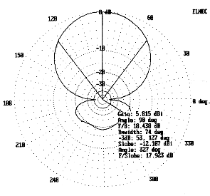
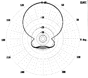
The chart for 12' aluminum elements shows a linear-loading element of #12 wire, spaced 0.1' (about 1.2") and 4' long corresponds closely to the 250- center-loading inductors. Substituting the required linear sections into the model yielded a 2-element beam with the same gain, front-to-back ratio, and feedpoint impedance as the center loaded model. Fig. 6 shows the free space azimuth pattern of the beam design. Since modeling an antenna with linear-loading sections requires extensive and careful element segment tapering techniques with MININEC programs, the resultant antenna description is quite large. Those with slower computers or restricted RAM may wish to skip this step and go directly from the graphs to the shop. However, it pays to check an extrapolated design to ensure against errors.
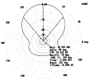
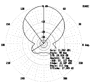
A 2-element beam, like every other array, will tend to vary in gain and front-to-back ratio at heights above real ground below about 2. As a check on the design, patterns were run at the angle of maximum radiation for heights of 20' and 35', with the results shown in Fig. 7 and Fig. 8. However, as usable as these performance expectations are, this step did not end the design process.
Because one of the main uses for shortened antennas is for portable field operations, I anticipated building the linear-loaded Yagi so as to make it transportable. Under these conditions, it is possible to add to the reflector a tuning capacitor remotely placed some multiple of a half-wavelength from the antenna and connected by a suitable length of parallel feeder (450-, in this case). This required lengthening the linear element of the reflector purposely to make it inductive. Lengthening the linear section of the reflector to 5' (2.5' either side of center) permitted the use of loading capacitance between about 50 and 95 pF to retune the reflector back to maximum front-to-back ratio.
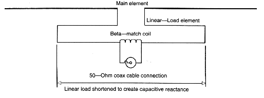
A second design modification was required by the use of a beta-match to convert the 17- feedpoint impedance to the 50- coax value. Shortening the driven element linear section to 3.7' (1.85' either side of center) yielded the requisite 23 ohms of capacitive reactance in the driven element to go with the 32.7- inductive reactance across the feedpoint terminals (0.18 µH or about 4 turns of #12 copper wire, 1/2" in diameter and 1/2" long at 8 turns per inch).5 Fig. 9 shows the general scheme of the beta match applied to the linear-loaded antenna.
These modifications for portable use actually improve one aspect of the antenna's performance: the SWR bandwidth. Fig. 10 is a graph of the SWR bandwidth of several antennas, all of which use the same main element dimensions: center-loaded Yagis with Qs of 300 and 100, the unmodified linear-loaded antenna, and the modified version for portable use. That the linear-loaded antenna is equivalent to a center-loaded beam with a Q well over 300 is obvious from the steepness of the SWR curve below the design frequency. The curve for the remotely tuned portable version shows a greater symmetry, with about 700 kHz of usable (<2:1) SWR bandwidth at optimum front-to-back ratio.
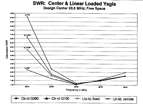
Actually, the antenna will tune within a 2:1 SWR across the entire first MHz of 10 meters. However, the front-to-back ratio will degrade at the band edges. Fig. 11 is a composite pattern of a fixed-reflector model between 28 and 29 MHz. Fig. 12 shows the composite free space azimuth pattern of the remotely tuned version over the same spectrum. The minor retuning required for bringing the SWR into the 2:1 range at the band edges does not reduce the front-to-back ratio very much.
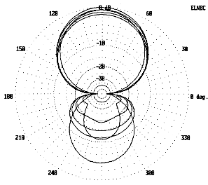
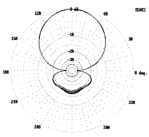
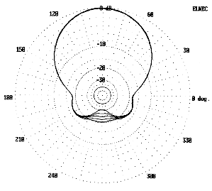
Tuning the reflector actually improves the front-to-back ratio over real ground relative to a fixed-reflector free-space-derived model. Fig. 13 and 14 show composite patterns for the first MHz of 10 for 20' and 35' elevations respectively, with the reflector in each case tuned for maximum front-to-back ratio. These patterns and numbers, of course, are anticipations bred from models. The final question is whether they can be realized.
Building a linear-loaded beam for portable field use (10-meter hilltopping) is not difficult, because the elements are light. The basic dimensions are these: Driven element: 11.6'; reflector: 12.16'; spacing: 4.25'. Four 6' lengths of 0.75" diameter tubing from the local hardware outlet provided the main elements. With a 2" center spacing, the reflector lengths are correct as purchased, but the driven elements were cut to 5'8" each.
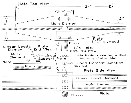
The element-to-boom plates are 1/2" plywood, about 6" to 7" wide and 2' long. As shown in Fig. 15, excess wood was removed from the corners for minimum weight. Each plate was coated with car-repair epoxy for fiberglass patching. This material is more weather-resistant than any other I have found. #10 stainless steel nuts, bolts, and lock washers fasten the element to the plate. (Small U-bolts are recommended for larger antennas.) Since the boom is a 5' section of 1 1/4" nominal diameter Schedule 40 PVC, 1 1/2" U-bolts make the plate-to-boom connection.
The plate-to-boom U-bolts also hold another fixture: the center supports for the linear-loading wire. The test antenna uses #12 solid copper wire linear sections in two pairs: two 2'6" sections for the reflector and two 1'5" sections for the driven element. Each section attaches to a thick plastic plate angled from the outer U-bolt inward, as shown in Fig. 15. A heavy plastic freezer box a little over 4" square and 1" high provided two plates that had the correct angle to place the linear-load wires directly under the main element when mounted to the outer U-bolts. The composition of the plastic ensures good weathering characteristics, and no RF problems have surfaced.
Wires a little over twice each section length were straightened and then bent over a piece of 1 1/4" mast to establish the spacing. Before mounting, I slipped mid-length and end supports over each wire loop. I cut eight 4" by 4" squares from the corners of a squared-off half-gallon plastic jug. On each side of each corner I used a hole-saw to cut 3/4" circles for the main elements and then drilled 1/8" holes for the linear-load wires. Squeezing the corners allows the wire and the main element to pass through each pair of holes. Releasing the corners places the assembly under tension, which keeps the main element and the linear-loading wires aligned. Local storm winds have not moved this assembly, but something stronger is recommended for larger or more permanently mounted antennas.
Solder rings on the ends of the linear-load wires attach the section to bolts (#10 stainless steel) on the center plastic plate. Short #12 wires, also with solder rings provide a junction between the wire assembly and the main aluminum element. Before attaching solder rings to wires, I usually let solder flow all over the ring, since many types will rust in the weather.
The driven element linear section terminates its lower center in a coaxial chassis connector mounted on the plastic plate with the threads facing the mast. A ferrite bead or shield 1:1 balun taped to the boom allows the coax to be run inside or outside the mast, in my case, sections of TV mast. The beta match coil mounts across the plate-to-linear-wire bolts with solder rings. The reflector section center terminates in two pin jacks. For initial testing, a capacitor with mating pins connects at the element. For field use, a half-wavelength of 450 parallel feeder terminated at one end with pins and at the other with pin jacks places the capacitor within easy reach for remote adjustment with 20' of mast. A series of plastic spray can tops, each punched with 4 holes for cable ties that clamp the mast and the feeder, space the feeder from the mast.
For testing, solder rings can be omitted from the linear section wires until the correct length is determined. Clamping the wires under washers at the plate will suffice for initial tests. The object is to obtain the lowest possible SWR at the center design frequency by first tuning the reflector capacitor for a minimum reading and then spreading or compressing the beta match turns for a final null. Adjust the length of the wire section to bring the null frequency to the design center. If initial test are close, then minor adjustments can be made by squeezing or spreading the linear wire sections (using the bottom wire only): squeezing lowers reactance and raises the frequency, while spreading increases reactance and lowers the frequency. If significant wire deforming is required, adjust the length instead.
Off center frequency, do not adjust the reflector capacitor for absolutely the lowest SWR. Instead, find the lowest SWR point and then slight off-tune the capacitor (within a 2:1 SWR ratio) in the direction of the setting for the antenna's design center frequency. That will establish a point closer to maximum front-to-back ratio in the absence of a reference signal. Refer to the SWR bandwidth graph for guidance.
The test antenna built to the specifications provided by the graphs and models performed to expectations. As indicated, the linear-loading element on the driven element was somewhat long, partly because the models yield slightly long dimensions and partly because the spacing used was slightly wider than the model for horizontal plane #12 wire elements at 0.1' spacing. Removing 3' of load wire on each side of center brought the antenna to resonance. The reflector element was also somewhat long, requiring a less capacitance than specified. At the design center frequency of 28.5 MHz, 27 pF brought the antenna to maximum front-to-back ratio. Matching required only a small adjustment of the beta-match coil, a matter of squeezing the turns slightly.
With a fixed reflector loading capacitor, the 2:1 SWR bandwidth of the antenna was slightly over 300 kHz, confirming its high Q. A variable capacitor in the reflector increased the bandwidth to nearly 1 MHz, with over 750 kHz of that bandwidth at maximum front-to-back ratio. Performance tests at a 20' height with local line-of-sight signals confirmed about 3 S-units of front-to-back ratio, although these rough tests cannot be equated with the elevated patterns shown in various figures. Nonetheless, they strongly suggest that the antenna performs close to its modeled specifications.
The 2-element linear-loaded Yagi has proven to be a most satisfactory field antenna. Although the linear load assembly on the elements requires some care, once assembled, it is almost as carefree as a full size 2-element Yagi. The added front-to-back ratio shows up in practice, while the half-dB reduction in gain does not. In a fixed-tuned model, the chief drawback is the narrower usable bandwidth: that configuration is most useful where the operator tends to use a small portion of the band. The field version with a tunable reflector overcomes this limitation in large measure, making this antenna a good competitor with a full-size 2-element Yagi.
In addition to yielding a buildable antenna, the modeling that has gone into the development of the linear-loaded Yagi demonstrates something else. Antenna modeling programs are not restricted to providing pattern-pictures of existing antennas. With proper care, they can be used to generate a considerable body of adjunct data of use to antennas builders. The calibration of linear-loading elements is but one example of techniques that can expand the utility of such programs. The more we can interconnect the direct data produced by such programs with other collections of data that are important to antenna design, the better we can understand the antennas we use. Whether this result or the development of linear-loaded Yagis is the more important result of the investigation is a question for fireside, coffee-cup debate on cold evenings when the bands are closed.
1 For more expert information on the construction of full size Yagis, see Leeson, Physical Design of Yagi Antennas (Newington: ARRL, 1992).
2 For example, see pages 6-7 and 6-8 of either the 16th or 17th Edition of the ARRL Antenna Book. See also pp. 11-22 and 11-23 of the 16th Edition for W0YNF's linear-loaded 14-MHz driven-element-director Yagi, which uses triangular geometry. A linear-loaded 40-meter dipole also appears in Orr and Cowan, Beam Antenna Handbook (Radio Publications, 1990), pp. 58-59. It uses vertical-plane geometry.
3 For somewhat greater accuracy, especially with large wires and close spacing, substitute for the given equation, the following:

4 Both MININEC 3.13 and NEC 2 are subject to systematic errors when combining elements of differential radii in complex geometries. The models used in this study are fully-tapered MININEC models. By extensive comparisons with various modeling techniques, including the use of single-wire-size substitutes for various parameters, the utility and general validity of the MININEC models was established. However, the linear-loads called for by those models may be up to 2 to 4 percent long, which closes the apparent gap between transmission-line calculations and the models. Nevertheless, extensive modeling, including modeling the antennas listed in note 2 above, establishes that triangular and vertical-plane geometries are not interchangeable without lengthening the linear-load element. Elements modeled in free space on W0YNF's dimensions and triangular geometry show a feedpoint reactance at 14.2 MHz of less than -10 , although a similar close-space vertical geometry model with the same dimensions show nearly -60 reactance (indicating a need to be longer to achieve resonance). Similarly, the vertical-plane geometry of the Orr dipole for 40 meters required a #12 wire linear load almost 8 feet longer than a #12 wire triangular linear load to achieve resonance with a 44.2-foot 1-inch diameter aluminum main element. The calculated triangular linear load modeled within 3- reactance of resonance.
5 A beta match is a form of L-section match in which the series capacitor is created by shortening the antenna element. A shunt coil completes the section that matches an antenna impedance of less than 50 to the higher impedance of the coaxial cable. Formulas for L-sections appear in almost any handbook. Designing an antenna for resonance on a modeling program and then shortening the driven element by an amount that yields the required value of capacitive reactance provides guidance for building the driven element, usually within limits that permit final adjustment by spreading or compressing turns in the shunt coil. A "hairpin" section of shorted transmission line can also make up the shunt inductor, usually with smaller losses, although the coil's lower Q permits a wider bandwidth. See the ARRL Antenna Book, 16th or 17th Edition, pp. 26-21 to 26-23, for further details, and be sure to read Thomas Cefalo, Jr., WA1SPI, "The Hairpin Match: A Review," Communications Quarterly (Summer, 1994), 49-54, and Gooch, Gardiner, and Roberts, "The Hairpin Match," QST (April, 1962), 11-14, 146, 156.
After developing the data and model antenna for linear loading, I ran across an article on a 10-meter 2-element Yagi that used 8' elements on a 4' boom with center-loading and a beta hairpin match.1 That led me to wonder how short we might make a Yagi, given that shortening elements permits an increase in front-to-back ratio at the expense of some gain. The results are interesting and worth passing on.
Modeled Performance of Shortened 10-Meter Dipoles


Antenna		Load		Feed				Gain in dBi

Length (ft)	 XL		Z		------------------------ Q= -----------------
		(Ohms)	  	(Ohms)		---	500	400	300	200	100

16.54
(full size)	  0		70.9		2.12

14'		131		43.0		2.02	1.98	1.97	1.96	1.94	1.83

12'		247		28.4		1.93	1.86	1.84	1.81	1.75	1.57

10'		366		18.1		1.87	1.70	1.66	1.59	1.46	1.07

8'		510		10.7		1.83	1.43	1.34	1.19	0.90	0.14

6'		697		 5.7		1.79	0.83	0.62	0.29	-0.29	-1.70

Table 1.  A comparison of the modeled performance characteristics of shortened center-loaded dipoles on 10-meters.
Beginning with center-loaded dipole performance, I modeled 0.75" aluminum elements ranging from full size (16.54') down to the point where gain in dBi fell below zero (6'). Table 1 summarizes the data, while Fig. 1 displays it in graphical form. The dipoles were initially modeled using infinite Q (0.0 Ohms resistance) and then rechecked at Qs of 500 down to 100. The infinite-Q reading provides a measure of the natural drop in basic gain as the antenna element becomes shorter. The finite Qs provide a measure of the losses incurred by center-loading the element to resonance with an inductor (or even a linear-loading element). Note the shape of the curve as the Q decreases linearly.
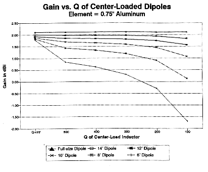
Although conventional, registering comparisons in terms of one gain figure as a percentage of another may not be greatly informative in making comparisons. Negative gains relative to an isotropic source are possible and do represent radiation by the antenna. The real question is whether the gain of any configuration is adequate to the job to which the antenna is assigned or whether something better may be available. The graph may give a better sense of the manner in which an antenna with decreasing length and centerload-Q may likely disappoint the builder if a full-size dipole is the standard of comparison.
Applying the dipole data selectively to full-size and shortened center-loaded 2-element Yagis produced the data in Table 2. The full-size Yagi used the 4' boom specified for the 8' model and is only a slight variation on the standard used throughout these tests. Models with 8' elements and with 12' elements were run at Qs from infinity to 100 to gauge the performance possibilities of half- and three-quarter-size antennas. With both shortened antennas, the front-to-back ratio is superior to a full-size 2-element Yagi at a cost in gain and SWR bandwidth. However, the 12' model shows a decrease in front-to-back ratio as the Q decreases, while the 8' model increases the front-to-back ratio with Q decreases down to 200.
Modeled Performance of Shortened 2-Element Yagis

Antenna				Gain		Front-to-Back		Feedpoint
  and				(dBi)		 Ratio (dB)		Impedance
 Load Q									  (Ohms)

Full-size Yagi1			6.63		 11.27			29.9

12' Elements
 ---				6.24		 21.22			16.7
 500				6.01		 19.98			17.2
 400				5.95		 19.70			17.3
 300				5.86		 19.25			17.6
 200				5.68		 18.43			18.0
 100				5.17		 16.38			19.3

8' Elements
 ---				5.76		 13.69			11.0
 500				4.88		 16.93			12.1
 400				4.68		 17.92			12.4
 300				4.36		 19.80			12.8
 200				3.78		 24.96			13.7
 100				2.34		 21.83			16.2

Note 1:  All antennas modeled with 0.75" aluminum elements and a 4' boom.  Full size antenna:
DE = 16.08'; Refl = 17.49'.  All driven elements resonated, although in practice, the matching
system may require a different length or load.

Table 2.  A comparison of modeled performance characteristics of center-loaded shortened 2-element Yagis.
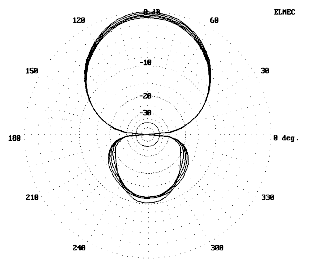
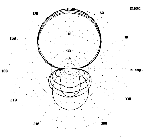
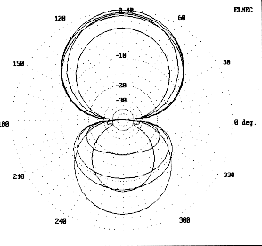
Fig. 2, 3, and 4 provide frequency-swept azimuth patterns in free space for the full-size, the 12' and the 8' models respectively. The full-size model, as expected, shows a consistent rear pattern throughout the 28 to 29 MHz range. In contrast, the rear pattern of the 12' model shows the narrow bandwidth of the maximum front-to-back ratio point, with usable front-to-rear ratios from 28.25 to 29 MHz, as compared to the full-size model. The rear pattern of the 8' model deteriorates much more quickly as the frequency departs from the 28.5 MHz design center. At 28.0 MHz, the antenna is essentially a lossy dipole.
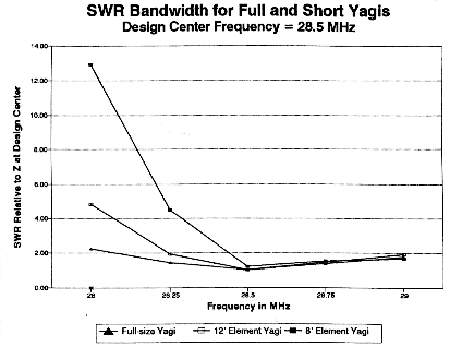
That the patterns of the shortened Yagis degrade more quickly below design center is also reflected in the SWR bandwidth curves shown in Fig. 5. Even the full size Yagi shows a steeper SWR curve below design center than above. The 12' model is well off match at 28 MHz, while the 8' model reaches a similar departure from match only 250 kHz below design center. The curves suggest that the antennas are best designed for a lower center-frequency, since the SWR increases slowly above that frequency. However sound that conclusion may be with respect to the full-size Yagi, it tells only part of the story with respect to the shortened models: one must also account for the degrading front-to-back ratio as the frequency departs upward from center.
Do the numbers condemn the shortest model? Not necessarily. Whether a particular antenna is right to build depends upon a collection of factors that perhaps only the user can balance. A full-size 2-element Yagi exhibits good gain within its class, about 2 S-units of front-to-back ratio, and a broad bandwidth, all at the expense of a larger physical structure. The 12' model shows a decreased bandwidth with respect to front-to-back ratio and SWR, but it maintains reasonably good gain and up to 3 S-units of front-to-back ratio with a size only three-fourths that of the full-size Yagi. The 8' model holds the appeal of a truly portable Yagi with some gain and 3 S-units of front-to-back ratio at its design center frequency. However, its gain is significantly reduced and its bandwidth is quite narrow. Moreover, with a feedpoint resistance in the neighborhood of 12 Ohms, the ratio of loss resistance to radiation resistance is much increased. Nevertheless, a small antenna with some gain over a dipole and a good front-to-back ratio over a narrow bandwidth can have many uses.
Both shortened antennas were modeled for patterns and SWR bandwidth curves at a centerload Q of 300, that obtainable on the 12' model with a linear-loading element. It is dubious whether such a Q could be sustained for either the 12' or the 8' model with inductive loading. Connection losses, weathering losses, and other factors are likely to reduce the Q of even the most elegant loading coil assemblies to levels below 100 unless the antenna is often cleaned or is operated within a protected environment. Unfortunately, as Table 2's data would suggest, these further reductions in gain might make the antenna less attractive as it weathers. However, for portable use--where assembly and disassembly provide reminders to clean all connections--the antenna may have its niche in the array of antennas in amateur use.
Like almost every other final evaluation question we have encountered, the inquiry, "How short can we go?" has no single reply. User needs, competing designs, parts availability, and building skills all contribute to the final answer for each ham.
1. Glenn Blackwell, K4HJJ, "A Half-size Two Element Beam with a Full Size Punch," 10-10 International News, 33 (Spring, 1995), 6.