 Three Forward-Stagger 5-Band Yagis from ON4ANT
Here is the brief account Johan shared about how he came to these designs:
"Having a 15 meter boom with a 4" diameter available made me think about the possibility of putting some elements to arrive at a beam that covered the 5 highest HF bands, 10 to 20 meters. The design goal was to achieve a gain for each band comparable to the gain of a 3-element monoband Yagi.
"As I started, I took several designs for monoband beams for 10, 15, and 20 meters and placed them on the boom. Then I added WARC band monobanders, and the result was very productive.
"The average gain for 3-element monobanders was 7.0 to 7.3 dBi (free space gain). After placing everything on the boom, the gain increased to over 8 dBi, an average increase of 1 dB per band. The designs looked to perform more like 4-element monobanders on all bands.
"The designs consist of 3 elements on 20, 3 elements on 17, 2 elements on 15, 2 elements on 12, and 4 elements on 10 meters. The result is an average gain of over 8.0 dBi free space, with excellent front-to-back ratio and good operating bandwidth for 14.0-14.28, 21.0-21.35, 28.0-28.6, and full WARC band coverage."

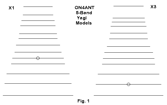
Figure 1 shows the outlines for the two designs. The first is focused on band coverage, while the second focuses on peak gain. At the end of this note are the modeling descriptions of the antennas, given both as AO models and as EZNEC model descriptions. The results of Johan's work have been cross checked on NEC-4, and, as one might expect for these untapered initial designs, the results are in close agreement.
Here are tables of performance figures from NEC-4 for each model, taking the band edges and the band center as markers. For the non-WARC bands, the limits are wider than John set as design goals, but the designs hold up well on almost all bands to the very limits of the wider bands.
14-28 X1

Frequency      Gain dBi       F-B dB         Z (R+/-jX)
14.0           8.07           28.38          32.7 - j 2.5
14.175         8.16           30.48          28.9 + j 5.4
  AO           (8.14)         (29.27)        (29.2 + j 5.1)
14.35          8.30           24.17          22.8 + j16.1

18.068         8.08           21.70          19.8 + j 3.5
18.118         8.09           22.08          21.1 + j 5.7
  AO           (8.11)         (23.75)        (23.7 - j 0.5)
18.168         8.11           22.52          22.8 + j 8.2

21.0           8.22           22.04          20.0 - j 0.8
21.225         8.29           21.78          32.0 + j 7.9
  AO           (8.21)         (20.96)        (34.8 + j 5.7)
21.45          8.39           21.60          34.5 + j16.2

24.89          8.59           25.08          12.9 + j 6.8
24.94          8.62           24.50          13.2 + j 8.7
  AO           (8.64)         (25.82)        (10.8 + j 4.0)
24.99          8.65           23.96          13.4 + j10.6

28.0           7.90           34.52          22.3 + j 0.6
28.5           8.15           24.59          23.0 + j16.2
  AO           (8.22)         (22.56)        (26.9 + j13.8)
29.0           8.42           19.98          23.4 + j33.2
Reference AO values for center band are included to show the agreement. Only the lowest end of 10 meters shows a gain lower than 8.0 dBi, and only the upper end of 10 meters shows a 180-degree front-to-back ratio under 20 dB (just barely). The lower source impedance of the 12-meter run is inevitable, given the nearness in length of the 10- and 12-meter elements, making almost all of the 10-meter elements added directors that increase 12-meter gain. On 10, the 12-meter elements function as added reflectors and have little influence on the 10-meter performance.
14-28 X3

Frequency      Gain dBi       F-B dB         Z (R+/-jX)
14.0           8.11           24.43          31.4 - j 5.3
14.175         8.18           23.45          31.5 + j 2.8
14.35          8.30           22.09          29.1 + j11.6

18.068         8.16           22.21          24.6 - j 1.3
18.118         8.18           22.80          25.3 - j 0.7
18.168         8.20           23.55          25.7 + j 0.1

21.0           8.39           19.78          26.2 - j 4.4
21.225         8.50           19.41          27.9 + j 5.2
21.45          8.61           19.10          29.5 + j14.8

24.89          8.65           25.90          13.2 + j 2.5
24.94          8.67           25.16          13.2 + j 4.3
24.99          8.70           24.50          13.1 + j 6.2

28.0           8.42           23.08          31.1 - j 1.0
28.5           8.57           21.57          20.0 + j 2.3
29.0           7.90           26.62           3.9 + j25.9
The X3 design achieves some added low band-end gain on some of the bands, especially 15-10 meters. However, there is some small sacrifice of front-to-back ratio on 15 and a narrower operating bandwidth on 10 meters. For some operating situations, these gain and sacrifices may be in order; for other operating situations, the broader X1 design may be favored.

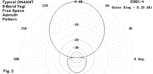
Figure 2 shows a typical pattern, with its very small rearward "ball" of gain. This pattern holds for almost all bands on both designs and is more typical of 4-element designs than of 3-element Yagis. Those who wish to model either or both of these antennas will benefit from examining the current tables to discover which elements are active to a significant degree as each band is fed.
The designs call for separate feeds, with the feed elements indicated in the AO models. All dimensions are in meters. US readers who model the antenna in EZNEC can convert the dimensions to feet or inches within the program. Incidentally, the 15-meter boom translates to about 49.2' long. The boom is similar to the boom length of a long 20-meter monobander, whose free space gain would be about 10.0 to 10.2 dBi for a well-designed 5-element version. See the note on the comparative performance of six 5/6-element 20 meter monobanders in another note in this series for further details. However, in the same space, Johan has packed 5 bands of 3+ element performance.
These designs are worth study and further experimentation.
====================================================================
AO model

14-28X1.ANT

114-18-21-24-28 yagi
;Over real ground
Free space
;14.150 MHz
;18.118 MHz
;21.200 MHz
;24.940 MHz
;28.300 MHz
14.175 MHz
13 wires, meters
r = 5.45       ;reflector20
s = 5.2             ;driver20
t = 4.9             ;dir 20
a = 4.15       ;reflector 17 + director2 20
b = 4.02       ;driver 17
d = 3.8             ;dir 17 + refl 15
e = 3.395      ;driver 15
f = 3.02       ;dir 15 + refl 12
g = 2.91       ;driver 12
h = 2.78       ;dir 12 + refl 12
i = 2.55       ;driver 10
j = 2.355      ;dir1 10
k = 2.265      ;dir2 10
;
pr = 0              ;refl 20
ps = 2              ;driver 20
pt = 3.6       ;dir 20
pa = 5.25      ;refl 17 -dir 20
pb = 6.2       ;driver 17
pd = 7.2       ;dir 17 - refl 15
pe = 8.4       ;driver 15
pf = 9.5       ;dir 15 - refl 12
pg = 10.3      ;driver 12
ph = 11.6      ;dir 12 - refl 10
pi = 12.45          ;driver 10
pj = 13.4      ;dir 10
pk = 15             ;dir2 10
dia = .02      ;tubing diameter --> must be tapered
shift z 24
;
1     pr -r 0    pr r 0   dia   ;14 refl
1     ps -s 0    ps s 0   dia   ;14 driven
1     pt -t 0    pt t 0   dia   ;14 dir1
1     pa -a 0    pa a 0   dia   ;18 refl - 14 dir2
1     pb -b 0    pb b 0   dia   ;18 driven
1     pd -d 0    pd d 0   dia   ;18 dir2 - 21 refl
1     pe -e 0    pe e 0   dia   ;21 driven
1     pf -f 0    pf f 0   dia   ;21 dir1 - 24 refl
1     pg -g 0    pg g 0   dia   ;24 driven
1     ph -h 0    ph h 0   dia   ;24 dir1 - 28 refl
1     pi -i 0    pi i 0   dia   ;28 driven
1     pj -j 0    pj j 0   dia   ;28 dir1
1     pk -k 0    pk k 0   dia   ;28 dir2
1 source
Wire 2, center    ; driver 20
;Wire 5, center    ; driver 18
;Wire 7, center    ; driver 15
;Wire 9, center    ; driver 12
;Wire 11, center    ; driver 10

========================================================
EZNEC model description

                      EZNEC/4  ver. 2.5

ON4ANT 5-b Yagi:  14-28xl                    08-28-1998     20:11:19


Frequency = 14.175  MHz.

Wire Loss: Aluminum -- Resistivity = 4E-08 ohm-m, Rel. Perm. = 1


              --------------- WIRES ---------------

Wire Conn. --- End 1 (x,y,z : m )  Conn. --- End 2 (x,y,z : m )   Dia(mm) Segs

1           -5.450,  0.000,  0.000         5.450,  0.000,  0.000 2.00E+01 37
2           -5.200,  2.000,  0.000         5.200,  2.000,  0.000 2.00E+01 35
3           -4.900,  3.600,  0.000         4.900,  3.600,  0.000 2.00E+01 34
4           -4.150,  5.250,  0.000         4.150,  5.250,  0.000 2.00E+01 28
5           -4.000,  6.200,  0.000         4.000,  6.200,  0.000 2.00E+01 27
6           -3.640,  7.200,  0.000         3.640,  7.200,  0.000 2.00E+01 25
7           -3.395,  8.400,  0.000         3.395,  8.400,  0.000 2.00E+01 23
8           -3.020,  9.500,  0.000         3.020,  9.500,  0.000 2.00E+01 21
9           -2.910, 10.300,  0.000         2.910, 10.300,  0.000 2.00E+01 21
10          -2.720, 11.600,  0.000         2.720, 11.600,  0.000 2.00E+01 19
11          -2.560, 12.450,  0.000         2.560, 12.450,  0.000 2.00E+01 19
12          -2.355, 13.400,  0.000         2.355, 13.400,  0.000 2.00E+01 17
13          -2.265, 14.800,  0.000         2.265, 14.800,  0.000 2.00E+01 16

              -------------- SOURCES --------------

Source    Wire      Wire #/Pct From End 1    Ampl.(V, A)  Phase(Deg.)  Type
          Seg.     Actual      (Specified)

1          18     2 / 50.00   (  2 / 50.00)      1.000       0.000       V

No loads specified

No transmission lines specified

Ground type is Free Space

========================================================
AO Model

14-28X3.ANT

14-18-21-24-28 yagi
;Over real ground
Free space
;14.150 MHz
;18.118 MHz
;21.200 MHz
;24.940 MHz
28.300 MHz
13 wires, meters
;r = 5.450          ;reflector20
;s = 5.152          ;driver20
;t = 4.892          ;dir 20
;a = 4.148               ;reflector 17 + director2 20
;b = 4.021          ;driver 17
;d = 3.802          ;dir 17 + refl 15
e = 3.375      ;driver 15
f = 3.019      ;dir 15 + refl 12
g = 2.905      ;driver 12
h = 2.781      ;dir 12 + refl 10
i = 2.6        ;driver 10
j = 2.498      ;dir1 10
k = 2.35       ;dir2 10
;
;pr = 0             ;refl 20
ps = 1.874          ;driver 20
pt = 3.6       ;dir 20
pa = 5.25      ;refl 17 -dir 20
pb = 6.194          ;driver 17
pd = 7.2       ;dir 17 - refl 15
pe = 8.21      ;driver 15
pf = 9.5       ;dir 15 - refl 12
pg = 10.487         ;driver 12
ph = 11.6      ;dir 12 - refl 10
pi = 12.34          ;driver 10
pj = 13.02          ;dir 10
pk = 15        ;dir2 10
dia = .02      ;tubing diameter --> must be tapered
;
1     0 -5.450 0     0  5.450 0   dia   ;14 refl
1     ps -5.142 0    ps 5.142 0   dia   ;14 driven
1     pt -4.820 0    pt 4.820 0   dia   ;14 dir1
1     pa -4.148 0    pa 4.148 0   dia   ;18 refl - 14 dir2
1     pb -4.021 0    pb 4.021 0   dia   ;18 driven
1     pd -3.802 0    pd 3.802 0   dia   ;18 dir2 - 21 refl
1     pe -e 0    pe e 0   dia   ;21 driven
1     pf -f 0    pf f 0   dia   ;21 dir1 - 24 refl
1     pg -g 0    pg g 0   dia   ;24 driven
1     ph -h 0    ph h 0   dia   ;24 dir1 - 28 refl
1     pi -i 0    pi i 0   dia   ;28 driven
1     pj -j 0    pj j 0   dia   ;28 dir1
1     pk -k 0    pk k 0   dia   ;28 dir2
1 source
;Wire 2, center    ; driver 20
;Wire 5, center    ; driver 18
;Wire 7, center    ; driver 15
;Wire 9, center    ; driver 12
Wire 11, center    ; driver 10

=====================================================================
                      EZNEC/4  ver. 2.5

ON4ANT 5-b Yagi:  14-28x3                    08-28-1998     20:11:52


Frequency = 14.175  MHz.

Wire Loss: Aluminum -- Resistivity = 4E-08 ohm-m, Rel. Perm. = 1


              --------------- WIRES ---------------

Wire Conn. --- End 1 (x,y,z : m )  Conn. --- End 2 (x,y,z : m )   Dia(mm) Segs

1           -5.450,  0.000,  0.000         5.450,  0.000,  0.000 2.00E+01 37
2           -5.142,  1.874,  0.000         5.142,  1.874,  0.000 2.00E+01 35
3           -4.820,  3.600,  0.000         4.820,  3.600,  0.000 2.00E+01 34
4           -4.148,  5.250,  0.000         4.148,  5.250,  0.000 2.00E+01 28
5           -4.021,  6.194,  0.000         4.021,  6.194,  0.000 2.00E+01 27
6           -3.802,  7.200,  0.000         3.802,  7.200,  0.000 2.00E+01 25
7           -3.375,  8.210,  0.000         3.375,  8.210,  0.000 2.00E+01 23
8           -3.019,  9.500,  0.000         3.019,  9.500,  0.000 2.00E+01 21
9           -2.905, 10.487,  0.000         2.905, 10.487,  0.000 2.00E+01 21
10          -2.781, 11.600,  0.000         2.781, 11.600,  0.000 2.00E+01 19
11          -2.600, 12.340,  0.000         2.600, 12.340,  0.000 2.00E+01 19
12          -2.498, 13.020,  0.000         2.498, 13.020,  0.000 2.00E+01 17
13          -2.350, 15.000,  0.000         2.350, 15.000,  0.000 2.00E+01 16

              -------------- SOURCES --------------

Source    Wire      Wire #/Pct From End 1    Ampl.(V, A)  Phase(Deg.)  Type
          Seg.     Actual      (Specified)

1          18     2 / 50.00   (  2 / 50.00)      1.000       0.000       V

No loads specified

No transmission lines specified

Ground type is Free Space
The following table gives the NEC-4 readouts of potential performance for the design frequency in each band, with data in () for the band edges. The numbers confirm the modeling results Johan derived from AO.
Freq.     Gain      F-B       Feed Impedance
MHz       dBi       dB        R +/- jX Ohms
20
(14.0     8.16      30.80     32.4 - j 2.4)
14.15     8.26      30.20     28.7 + j 5.7
(14.35    8.40      23.03     22.8 + j16.4)
17
18.118    8.26      21.29     30.5 + j 6.9
15
(21.0     8.70      23.13     29.5 + j 2.5)
21.2      8.79      23.33     32.4 + j10.5
(21.45    8.92      23.45     35.4 + j20.1)
12
24.89     9.57      36.73     24.4 + j 9.3
10
(27.6     9.58      21.86     20.4 - j17.1)
(28.0     9.79      26.48     22.0 - j 7.1)
28.35     9.88      38.14     23.3 + j 3.2
(28.8     9.50      31.15     24.8 + j 1.0)
(28.9     9.29      31.34     15.8 + j 1.1)
(29.0     8.90      31.07      7.8 + j 7.4)
Band edge data for 10 meters includes extra checks, which show that the operating cut-off is about 28.85 MHz, although some "surplus" performance and matchable feedpoint impedance exist below the lower end of 10-meters.
The AO and EZNEC descriptions are appended for those wishing to model this extraordinary design. The two models correspond wire for wire, so that the driven element locations for each band listed in the AO model also apply to the EZNEC model.
==================================================
AO Model
14->28 yagi
;gain & F/B is 8.2/30 8.2/21 8.7/23 9.4/31 9.85/27
Free space
14.150 MHz
;18.118 MHz
;21.200 MHz
;24.940 MHz
;28.350 MHz
14 wires, meters
r = 5.45  ;refl  20
s = 5.2  ;driver20
t = 4.9  ;dir   20
a = 4.15          ;refl  17
b = 4   ;driver17
d = 3.64  ;refl  15
e = 3.4  ;driver15
f = 3.02  ;refl  12
g = 2.9  ;driver12
h = 2.68  ;refl  10
i = 2.55  ;driver10
j = 2.47  ;dir1  10
k = 2.44  ;dir2  10
l = 2.31  ;dir3  10
;
pr = 0            ;refl  20
ps = 2            ;driver20
pt = 3.6         ;dir   20
pa = 5.25      ;refl  17 - dir 20
pb = 6.4        ;driver17
pd = 7.2        ;dir   17 - refl 15
pe = 8.4        ;driver15
pf = 9.5         ;dir   15 - refl 12
pg = 10.8      ;driver12
ph = 12         ;dir   12 - refl 10
pi = 12.914   ;driver10
pj = 13.829   ;dir   10
pk = 15.556  ;dir2  10
pl = 17.944    ;dir3  10
dia = .02
1     pr -r  0     pr  r  0   dia   ;14 refl
1     ps -s 0     ps  s  0   dia   ;14 driven
1     pt -t  0     pt   t  0   dia   ;14 dir
1     pa -a 0     pa  a 0   dia   ;18 refl
1     pb -b 0    pb  b 0   dia   ;18 driven
1     pd -d 0    pd d  0   dia   ;18 dir2 - 21 refl
1     pe -e 0     pe e  0   dia   ;21 driven
1     pf  -f  0     pf  f  0   dia   ;21 dir1 - 24 refl
1     pg -g 0     pg g  0   dia   ;24 driven
1     ph -h 0     ph h  0   dia   ;24 dir1 - 28 refl
1     pi -i   0     pi  i   0   dia   ;28 driven
1     pj -j   0    pj  j   0   dia   ;28 dir
1     pk -k 0    pk k  0   dia   ;28 dir 2
1     pl  -l  0    pl   l   0   dia   ;28 dir 3
1 source
Wire 2, center     ; driver 20
;Wire 5, center    ; driver 17
;Wire 7, center    ; driver 15
;Wire 9, center    ; driver 12
;Wire 11,center    ; driver 10
==================================================
                      EZNEC/4  ver. 2.5

ON4ANT 5-b Yagi:  14-28X2                    04-18-1999     17:55:29


Frequency = 14.175  MHz.

Wire Loss: Aluminum -- Resistivity = 4E-08 ohm-m, Rel. Perm. = 1


              --------------- WIRES ---------------

Wire Conn. --- End 1 (x,y,z : m )  Conn. --- End 2 (x,y,z : m )   Dia(mm) Segs

1           -5.450,  0.000,  0.000         5.450,  0.000,  0.000 2.00E+01  37
2           -5.200,  2.000,  0.000         5.200,  2.000,  0.000 2.00E+01  35
3           -4.900,  3.600,  0.000         4.900,  3.600,  0.000 2.00E+01  34
4           -4.150,  5.250,  0.000         4.150,  5.250,  0.000 2.00E+01  28
5           -4.000,  6.400,  0.000         4.000,  6.400,  0.000 2.00E+01  27
6           -3.640,  7.200,  0.000         3.640,  7.200,  0.000 2.00E+01  25
7           -3.400,  8.400,  0.000         3.400,  8.400,  0.000 2.00E+01  23
8           -3.020,  9.500,  0.000         3.020,  9.500,  0.000 2.00E+01  21
9           -2.900, 10.800,  0.000         2.900, 10.800,  0.000 2.00E+01  21
10          -2.680, 12.000,  0.000         2.680, 12.000,  0.000 2.00E+01  19
11          -2.550, 12.914,  0.000         2.550, 12.914,  0.000 2.00E+01  19
12          -2.470, 13.829,  0.000         2.470, 13.829,  0.000 2.00E+01  17
13          -2.440, 15.556,  0.000         2.440, 15.556,  0.000 2.00E+01  16
14          -2.310, 17.994,  0.000         2.310, 17.994,  0.000 2.00E+01  16

              -------------- SOURCES --------------

Source    Wire      Wire #/Pct From End 1    Ampl.(V, A)  Phase(Deg.)  Type
          Seg.     Actual      (Specified)

1          18     2 / 50.00   (  2 / 50.00)      1.000       0.000       I

No loads specified
No transmission lines specified
Ground type is Free Space

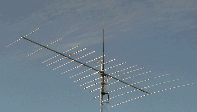
Johan has sent me the "final" or constructed version of his 5-band forward stagger Yagi. He has made a few changes in structure to improve 10-meter performance, especially at the lower end of the band. The result was a 0.25-m lengthening of the boom, plus some spacing changes and some minor element length changes. The model he sent me now uses nontapered elements, but of different diameters that increase as the frequency decreases. This technique allowed him to better approximate the behavior of the beam when the tapered-diameter elemnent schedule was added before construction. The photograph attests to both the size and the construction quality of the antenna.

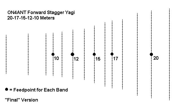
The sketch, taken from an EZNEC antenna view, better shows the final proportions and the location of the feedpoints. The following table shows the modeled performance of the antenna as forecast by NEC-4.
Freq.     Gain      F-B       Feed Impedance
MHz       dBi       dB        R +/- jX Ohms
20
14.0      8.30      36.74     28.8 - j 0.4
14.175    8.41      27.35     24.7 + j 7.9
14.35     8.55      20.57     19.0 + j18.8
17
18.118    8.35      23.06     31.7 - j 4.9
15
21.0      8.73      23.12     34.1 + j 2.0
21.225    8.86      23.15     35.9 + j10.3
21.45     8.99      23.04     37.4 + j18.6
12
24.94     9.70      37.50     23.4 + j14.6
10
28.0      9.92      26.58     30.0 - j 8.8
28.35     9.99      39.15     33.5 - j 4.7
28.7      9.69      34.30     20.3 - j12.2
Gain figures are up a bit, with the F-B ratio maintained and good coverage across all of four bands and the portion of the 10-meter band of interest to Johan. He reports that gamma matches for each band were easily set up for most bands, with only a couple that he would like to tweak up a bit. His initial tests against a neighbor's large commercial multi-band Yagi at the same height and over similar terrain give the forward-stagger design a considerable advantage--something over an S-unit on his rig. For reference, I am adding Johan's AO file and the EZNEC model description I used to obtain the projected free space operating parameters. Johan's design work will appear in an issue of the Belgian national amateur radio society journal. It will include extensive construction details.
==============================================================
AO File:
14->28 yagi
; gain calculated is 8.3/34 8.3/21 8.7/23 9.6/38.4 10.0/29.0 in free space
Free space
14.150 MHz
;18.118 MHz
;21.200 MHz
;24.940 MHz
;28.350 MHz
14 wires, meters
r = 5.45		;refl  20
s = 5.2		;driver20
t = 4.9		;dir   20
a = 4.15		;refl  17
b = 4.02		;driver17
d = 3.8		;refl  15
e = 3.395		;driver15
f = 3.02		;refl  12
g = 2.91		;driver12
h = 2.68		;refl  10
i = 2.55		;driver10
j = 2.47		;dir1  10
k = 2.44		;dir2  10
l = 2.31		;dir3  10
;
pr = 0		;refl  20               32mm
ps = 2.0		;driver20               32mm
pt = 3.6		;dir   20               32mm
pa = 5.25		;refl  17 -dir 20       32mm
pb = 6.4		;driver17               25mm
pd = 7.2		;dir   17 - refl 15     25mm
pe = 8.4		;driver15               25mm
pf = 9.5		;dir   15 - refl 12     25mm
pg = 10.8		;driver12               25mm
ph = 12.0		;dir   12 - refl 10     23mm
pi = 13.014		;driver10               23mm
pj = 13.816		;dir   10               23mm
pk = 15.775		;dir2  10               23mm
pl = 18.25		;dir3  10               23mm
dia = .023
diam = .032
dian = .025
;I use different element diameters for the differnent bands
;it makes things easier afterwards, when you want to taper
shift Z 24
1     pr -r 0    pr r 0   diam   ;14 refl
1     ps -s 0    ps s 0   diam   ;14 driven
1     pt -t 0    pt t 0   diam   ;14 dir1
1     pa -a 0    pa a 0   dian   ;14 dir2 - 18 refl
1     pb -b 0    pb b 0   dian   ;18 driven
1     pd -d 0    pd d 0   dian   ;18 dir2 - 21 refl
1     pe -e 0    pe e 0   dian   ;21 driven
1     pf -f 0    pf f 0   dian   ;21 dir1 - 24 refl
1     pg -g 0    pg g 0   dian   ;24 driven
1     ph -h 0    ph h 0   dia    ;24 dir1 - 28 refl
1     pi -i 0    pi i 0   dia    ;28 driven
1     pj -j 0    pj j 0   dia    ;28 dir1
1     pk -k 0    pk k 0   dia    ;28 dir2
1     pl -l 0    pl l 0   dia    ;28 dir3
1 source
Wire 2, center    ; driver 20
;Wire 5, center    ; driver 18
;Wire 7, center    ; driver 15
;Wire 9, center    ; driver 12
;Wire 11,center    ; driver 10
;
;Important note: Those wishing to increase gain on 20m can easely do this without
;too much sacrifice, making the 18Mhz reflector longer will increase the gain with 0.5 db
;Given the fact I use a gamma match and wanted to avoid nasty surprices like freq shift
;when putting the antenna on top of a 80ft tower, I preferred the wide bandwith.
=============================================================
                      EZNEC/4  ver. 2.5

ON4ANT 5-b Yagi:  14-28 Final                07-16-1999     08:02:03

Frequency = 14.175  MHz.
Wire Loss: Aluminum -- Resistivity = 4E-08 ohm-m, Rel. Perm. = 1

              --------------- WIRES ---------------

Wire Conn. --- End 1 (x,y,z : m )  Conn. --- End 2 (x,y,z : m )   Dia(mm) Segs

1           -5.450,  0.000,  0.000         5.450,  0.000,  0.000 3.20E+01  37
2           -5.200,  2.000,  0.000         5.200,  2.000,  0.000 3.20E+01  35
3           -4.900,  3.600,  0.000         4.900,  3.600,  0.000 3.20E+01  34
4           -4.150,  5.250,  0.000         4.150,  5.250,  0.000 2.50E+01  28
5           -4.020,  6.400,  0.000         4.020,  6.400,  0.000 2.50E+01  27
6           -3.800,  7.200,  0.000         3.800,  7.200,  0.000 2.50E+01  25
7           -3.395,  8.400,  0.000         3.395,  8.400,  0.000 2.50E+01  23
8           -3.020,  9.500,  0.000         3.020,  9.500,  0.000 2.50E+01  21
9           -2.910, 10.800,  0.000         2.910, 10.800,  0.000 2.50E+01  21
10          -2.680, 12.000,  0.000         2.680, 12.000,  0.000 2.30E+01  19
11          -2.550, 13.014,  0.000         2.550, 13.014,  0.000 2.30E+01  19
12          -2.470, 13.816,  0.000         2.470, 13.816,  0.000 2.30E+01  17
13          -2.440, 15.775,  0.000         2.440, 15.775,  0.000 2.30E+01  16
14          -2.310, 18.250,  0.000         2.310, 18.250,  0.000 2.30E+01  16

              -------------- SOURCES --------------

Source    Wire      Wire #/Pct From End 1    Ampl.(V, A)  Phase(Deg.)  Type
          Seg.     Actual      (Specified)

1          18     2 / 50.00   (  2 / 50.00)      1.000       0.000       I

No loads specified
No transmission lines specified
Ground type is Free Space
Updated 08-28-98; 4-18-99, 7-16-99. © L. B. Cebik, W4RNL. Data may be used for personal purposes, but may not be reproduced for publication in print or any other medium without permission of the author.