There is a very interesting 20-meter Yagi design called the Optimized Wideband Antenna, or OWA. Although only one of several designs within this genre, developed by Nathan Miller, NW3Z and Jim Breakall, WA3FET, using an optimizer program no longer available, the 20-meter version is one of the most adaptable. It employs 6-elements in the space that many other designs use 5. Fig. 1 shows the general proportions of the antenna.
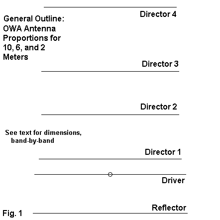
The 20-meter antenna has several features that deserve special note. Director 1 is perhaps the most significant, since it represents the added element to previously standard 5-element designs. By the use of this parasitic element, the driver can be more closely spaced to the reflector and still show a feedpoint impedance very close to 50 Ohms resistive. Moreover, the antenna shows wideband VSWR characteristics, with values less than a 1.3:1 from 14.0 through 14.35 MHz.
Not only is the feedpoint impedance quite stable, so too are the other main operating characteristics, including both gain and the front-to-back ratio. The antenna shows better than 10 dBi forward gain in free space models across the entire 20 meter band, with more than a 20 dB front-to-back ratio across the same span. Many 5-element designs show much larger variations in all three of the main Yagi parameters: gain, front-to-back ratio, and feedpoint impedance.
The remaining elements of the OWA are also interesting. Directors 2 and 3 are either the same length or the forward director is slightly longer than the rearward member of the pair. Director 4 and the reflector are available for making small changes in the upper and lower frequency limits of the design to spread the operating characteristics across the desired bandwidth. The 20-meter band is about 2.5% of its center frequency. The OWA is capable if significantly greater operating bandwidths with little loss in any of its main characteristics.
The reason for making extensive note of the OWA design is that it scales quite easily (but not without some readjustment) to create very usable Yagis for 10, 6 and 2 meters. Although only a few hams have the wherewithal to construct a 48' boom Yagi for 20 meters, 24'-boom Yagis for 10 are more common--and more manageable. The same antenna, scaled and adjusted for 6 meters sits on a boom just over 13' long. On 2 meters, the boom is only a small bit longer than 4.5'. In all cases, the resultant beams show free space gains above 10 dBi across the bands, front-to-back ratios always in excess of 20 dB, and very low 50-Ohm VSWR ratios for direct coax feed systems.
Let's look at the designs for each band, one at a time.
A 10-Meter, 6-Element OWA Yagi
Scaling the initial OWA to 10 meters involved two approaches. One was the direct approach of frequency scaling each element of the original, along with the element spacing and the element diameters. The elements of the 20 meter version used a complex array of tubing sizes from 0.5" to 1.0" in 1/8" increments. For 10-meters, the roughly half size tubing required by direct scaling is not either usual or recommended for most Yagi designs.
The second approach was to convert the 20-meter design into its equivalent uniform diameter element equivalent, scale this antenna, and then create a set of tapered diameter elements suitable for 10 meters, adjusting their lengths to be equivalent to the substitute model. The following table lists, in order, the overall element length, the spacing from the reflector, and the exposed tubing lengths of each size tubing used on one side of the element. (Be sure to double the length of the largest size tubing and to have extra inches on the remaining sections for the tubes to nest.) All dimensions are in inches.
Element   Overall        Spacing        0.5"           0.375"         0.25"
          Length         from Refl.     Inner          Middle         Outer
Reflector 216.8          ------         35.75          35.75          36.9
Driver    209.2           44.68         35.75          35.75          33.1
Dir 1     199.36          69.26         35.75          35.75          28.18
Dir 2     193.23         132.40         35.75          35.75          25.12
Dir 3     193.24         192.83         35.75          35.75          25.12
Dir 4     186.05         282.96         35.75          35.75          21.53
The antenna was scaled and reset to cover the span from 28 to 29 MHz. Some adjustment of the reflector and 4th director was required to achieve the added bandwidth. The first MHz of 10 meters represent a 3.5% operating bandwidth, about 40% greater than demanded of the 20-meter version of the antenna. The following table shows representative modeled figures for 5 points across the band. All figures are based on free space models using NEC-4.1 with Leeson corrections invoked for greatest accuracy.
Parameter      28.0      28.25     28.5      28.75     29.0
Gain dBi       10.00     10.10     10.19     10.26     10.27
F-B dB         20.29     26.57     30.22     24.47     21.34
Feed Z:
   R           38.4      41.9      44.4      44.6      36.5
   jX          +5.0      -1.1      +1.3      +0.5      -2.6
50-Ohm SWR     1.33      1.20      1.13      1.12      1.38
The greater bandwidth demanded of the 10-meter design shows most clearly in the rise in SWR and decrease in feedpoint impedance at the low and high ends of the bandpass. Nonetheless, the design meets all of the objectives. The gain changes only by about a quarter dB across the band. With further tweaking, the feedpoint impedance might be brought upward toward 50 Ohms a bit, but the reactance figures are extremely low for an antenna covering a full MHz of 10 meters. All of this suggests that the OWA design concept is capable of significant expansion beyond its original implementation.
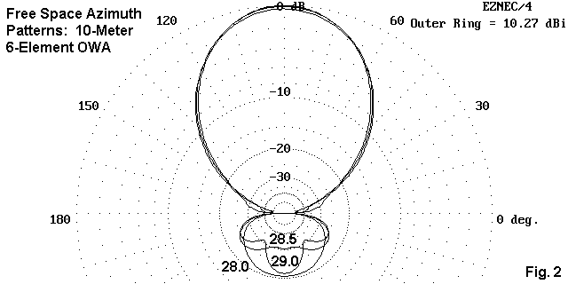
The antenna pattern itself is a model of good behavior, with no undesirable side or rear lobes. Note in Fig. 2 the change in the shape of the rearward lobe across the band, which is a normal progression for well-behaved antennas of this type.
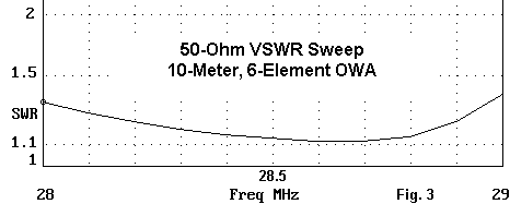
Just for the drama, Fig. 3 shows the 50-Ohm SWR sweep, taken at 0.1 MHz intervals across the band. There are no impedance spikes anywhere in the bandpass of the antenna.
As a high-performance 10-meter antenna covering all of the first MHz of the band, the 24' 6-element OWA is a worthy monoband competitor with other designs for the band.
A 6-Meter, 6-Element OWA Yagi
The (re-)design goal that I set for myself on 6 meters was to see if the antenna could be reset to hold its characteristics across the first 2 MHz of the band. Centered on 51 MHz, the design sought to have a free space gain of at least 10 dBi, a front-to-back ratio of more than 20 dB, and a low 50-Ohm VSWR from 50 to 52 MHz. The operating bandwidth is 3.9% of the center frequency, or 62% wider than the original 20-meter version.
At 6 meters, the element taper can be simplified to two steps: 0.5" for the center section and 0.375" for the outer sections. Here is a table of the final dimensions used in the design exercise. As always, physical dimensions are in inches.
Element   Overall        Spacing        0.375"         0.25"
          Length         from Refl.     Inner          Outer
Reflector 119.00         ------         24.50          35.00
Driver    116.61          29.56         24.50          33.80
Dir 1     109.07          41.79         24.50          30.03
Dir 2     105.95          75.65         24.50          28.48
Dir 3     105.96         108.79         24.50          28.48
Dir 4     101.80         158.21         24.50          26.40
The overall antenna length is just about 13.2' which permits construction of the antenna on a 14' boom. The operating characteristics of the model are summarized in the following table.
Parameter      50.0      50.5      51.0      51.5      52.0
Gain dBi       10.06     10.16     10.24     10.26     10.17
F-B dB         20.25     26.51     30.45     23.71     20.34
Feed Z:
   R           46.6      49.2      51.8      50.3      34.2
   jX          +5.2      +8.2      +8.9      +3.7      -0.0
50-Ohm SWR     1.14      1.18      1.20      1.08      1.46
The source impedance is closer to 50 Ohms than was true of the 10-meter version of the antenna, but the reactance values are also higher than on 10 meters. Instead of a continuous rise in gain across the band, the 6-meter version of the design shows a distinct gain peak between 51.0 and 51.5 MHz. The front-to-back curve parallels that of the 10-meter version. I note these similarities and differences should someone be of a mind to further optimize these adapted designs from the original OWA.
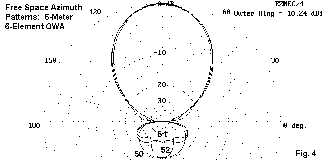
The azimuth patterns for the antenna are virtually identical to those for the 10-meter version, as shown in Fig. 4. This includes the slight bulge in the forward pattern near the 90-degree mark (relative to the forward gain bearing) at the high end of the band.
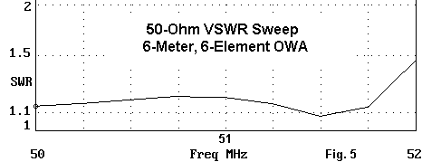
The SWR sweep in Fig. 5 shows a different pattern than the corresponding 10-meter sweep. The SWR figure, always low, tends to meander across the band, hitting a low point before ascending to 1.46 at the high end of the band. Although the figures are all quite acceptable, further optimizing might bring down the figure at the high end of the band by raising the resistive component of the impedance.
Most high gain work on 6 meters occurs at the lowest end of the band. This fact may limit the utility of the OWA design. However, the 2 MHz operating bandwidth of the design does demonstrate the reasonably high and well-behaved gain can be attained across a considerable portion of 6 meters.
A 2-Meter, 6-Element OWA Yagi
2-meters is filled with Yagis and variants that provide mediocre gain and operating bandwidth on longer than necessary booms. An adaptation of the OWA for 2 meters can provide 10 dBi free space gain on a 4.5' boom, which is under two-thirds of a wavelength. At 2-meters, we can use uniform element diameters for ease of construction.
The adaptation of the OWA to 2 meters employs 3/16" diameter elements (presumably aluminum rods). The following table summarizes the dimensions, again in inches.
Element   Overall        Spacing        0.1875"
          Length         from Refl.
Reflector  40.52         ------         20.26
Driver     39.96          10.13         19.98
Dir 1      37.38          14.32         18.69
Dir 2      36.31          25.93         18.16
Dir 3      36.31          37.28         18.16
Dir 4      34.96          54.22         17.48
As in all of the tables of physical dimensions, the numbers are fussier than reality. However, the extra decimal place may be useful in letting the builder round off in the direction he or she deems most fitting to the particular construction method being used.
The design goal of this exercise was to attain an operating bandwidth covering all of the 2-meter band. Although 4 MHz sounds impressive, it is only 2.7% of the center frequency (146 MHz), so the exercise proved fairly easy. The following table lists the modeled operating characteristics across the band.
Parameter      144       145       146       147       148
Gain dBi       10.13     10.19     10.23     10.22     10.16
F-B dB         22.01     28.12     35.36     26.77     22.21
Feed Z:
   R           44.8      47.2      50.0      50.9      43.7
   jX          +7.6      +9.6      +9.5      +5.2      -1.7
50-Ohm SWR     1.21      1.23      1.21      1.11      1.15
The narrower bandpass requirements of this version of the OWA yielded a peak gain and front-to-back ratio very close to the design center frequency. The figures, in fact, are very similar to those for the original 20-meter version which is the basis for all of these scalings.
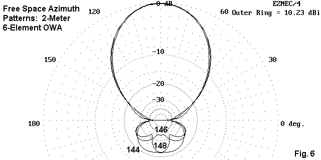
The free space azimuth patterns in Fig. 6 for the band edges and center are virtually indistinguishable from those of the other two designs. Only the slightly improved front-to-back levels at the band edges show up as something noticeable on the plots.
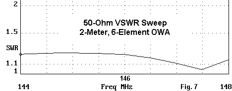
The SWR sweep across 2 meters in Fig. 7 is similar to that of the 6-meter beam, although the smaller bandpass does not require us to use the steeper portion of the curve above 148 MHz.
For a high-performance, compact (4.5' boom), and inexpensive 2-meter beam, one could do far worse than the adapted OWA design shown here. With some further optimizing, one might even do a wee bit better.
Conclusion
All credit for the OWA design belongs to its originators. This exercise has only shown that one of the implementations of the basic design can be advantageously adapted to other bands. None of the models presses any limit of the NEC and, therefore, they are quite reliable, both as analyses of the antennas and as guides to construction. Of course, using other element diameter taper schedules than the ones shown will require resetting the element lengths to accommodate the materials used.
The OWA has the following positive characteristics:
In addition to being rather good Yagis of their size, the OWA designs may also serve as a standard against which to measure other designs that present themselves. Even if you never build one of these designs, the data provided here may be useful for comparative purposes.
Updated 9-1-99. © L. B. Cebik, W4RNL. This item first appeared in AntenneX, Aug., 1999. Data may be used for personal purposes, but may not be reproduced for publication in print or any other medium without permission of the author.