 Getting the Most Out of Antenna
Patterns
Ham journals are filled these days with antenna pattern graphics, like the pair shown in Figure 1.1 The patterns are supposed to be highly informative about antenna performance. Unfortunately, to the new ham, they can be somewhat bewildering. Even the experienced ham may not be getting from them all the information that is compactly presented in the patterns. So let's start from scratch, seeing how these patterns represent antenna data that is useful to us, whether we plan to buy an antenna or build our own.
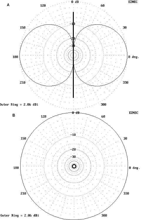
Although modern antenna modeling software produces data that can yield many different kinds of antenna patterns, the most common ones are called total far field patterns. They combine all calculated radiation from an antenna in every direction and produce a pattern that is related to a constant strength. In Figure 1, we can see that the pattern bulges and indents. Incidentally, the bulges are called lobes and the indentations are called nulls.
Hypothetically, if we stand on a line proportional to the pattern line distance from the center point (where the antenna is located), we shall receive a radiated signal of constant strength, no matter where on the line we stand. Likewise, if someone moves a transmitter along the line, then the antenna we are using will receive a signal of constant strength, no matter where along the line we place the transmitter. In short, antenna patterns reflect both transmission and reception characteristics of the antenna being patterned, where the lobes indicate stronger signals and the nulls indicate weaker ones.
Mastering the art of reading antenna patterns intelligently requires that we learn a number of ideas and conventions. Some relate to antenna theory itself. Some emerge from antenna modeling. Still others come from actually building and testing antennas on carefully constructed ranges. So our short story cannot end here. However, if we learn to sort out the key factors that are relevant to a particular antenna pattern we encounter, we can read them as easily as the words on this page.
Let us begin in free space. Unlike the reflective surface of the earth, free space is a region in which there is nothing but the antenna. In fact, the patterns in Figure 1 are free space patterns of a common horizontal resonant half-wavelength dipole fed at the center. Figure 2 shows a complete 3-dimensional view of the antenna pattern. The antenna is grossly exaggerated in size to clarify its position through the center of the pattern. In reality, it would be too small to be seen.
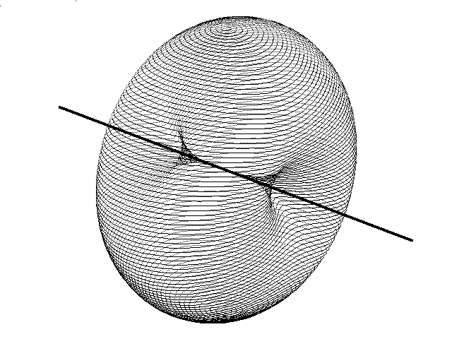
The first thing to notice is that the pattern is symmetrically even all around the wire when viewed from the wire end. That symmetry shows up in Figure 1B. However, the radiation is not so even when viewed as a slice through the pattern in the plane of the wire. That is the view shown in Figure 1A.
The difference between the two patterns reflects a fundamental property of antennas. They emit (and receive) radiation in two planes, conventionally called the E and H planes. The radiation in the E-plane is parallel with the wire. An antenna pattern taken parallel to the wire is also called an E-plane pattern. If we slice the 3-D pattern at any angle, but always barely include the antenna wire's total length, we shall in free space obtain the pattern of Figure 1A. Every plane will show the same indentations in field strength off the ends of the dipole wires.
There is also radiation at right angles to the wire. By convention, if we take a slice, normally through the center of the antenna element, but at right angles to the wire, we have an H-plane pattern. This is the pattern of Figure 1B.
However, the two patterns in the figure are not marked E- and H-plane. Instead, they carry a more conventional designation used these day: azimuth and elevation. We use these terms because most of our actual antennas are place above the earth, and the planet gives us a nearly flat reference plane to give meaning to the ideas of horizontal and vertical, and also to azimuth and elevation.
When we have more complex antenna arrays, the E-plane and H-plane
patterns become even more rigorous. See Figure 3. Here we have a
3-element Yagi. The E-plane not only parallels the length of the main
element, but as well passes through the plane formed by the 3 elements.
The H-plane is at right angles and is normally centered on the driven
element, to which is connected the signal source. The elements of this
antenna form a horizontal line across the H-plane.
E-plane and H-plane patterns for antennas are convenient is free
space. In a region of space, we do not have any reflecting surfaces, so it
does not matter in what orientation we place an antenna. We can always
derive E-plane and H-plane patterns. The patterns are significant in just
this way: when we place an antenna horizontally relative to the earth, the
E-plane pattern will dominate the azimuth pattern we derive. When we place
the antenna at right angles to the earth at any height, that is, when we
make it vertical, the H-plane pattern will dominate the azimuth pattern we
derive.
In Figure 1, I could have set up the antenna vertically instead of
horizontally in the software frame of reference. Had I done that, then the
same two patterns would have emerged, but in reverse order. The elevation
pattern would now correspond to the E-plane and the azimuth pattern would
be the H-plane. In free space, that is the only difference of note.
However, once we return to earth, the difference in orientation will make a
big difference in how the antennas work.
Just to make life a little more complicated, we should note in passing
that in NEC, the most used antenna modeling core, the native orientation to
antenna positions is not azimuth and elevation. NEC refers to ? (phi) and
? (theta) angles. Phi corresponds to azimuth, referenced to a zero point.
However, theta is a "zenith" angle. That is, instead of counting in
degrees up from the ground (or whatever is designated as the horizontal
plane in free space), it counts down from directly overhead. If you see
the "theta" notation, you can obtain the elevation angle just by
subtracting the theta angle from 90 degrees.
I plotted these antennas in this way to illustrate that you may see
different conventions used by different software in the production of
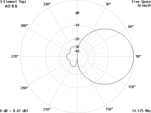
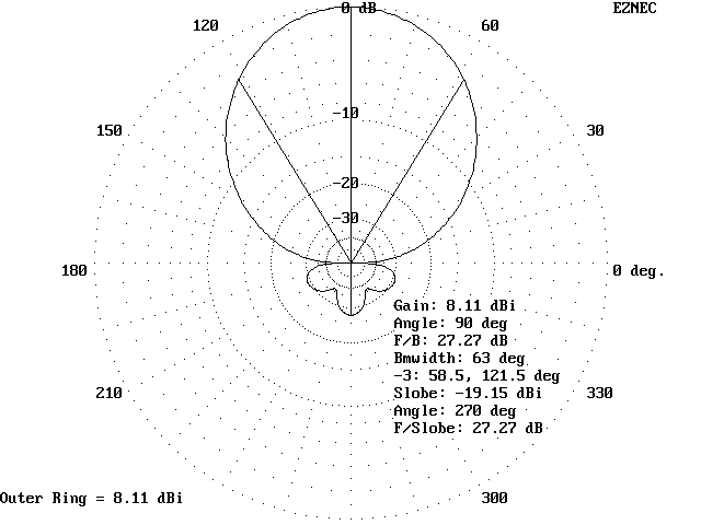
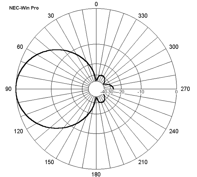
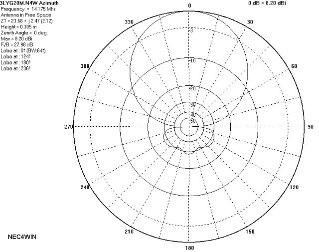
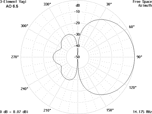
antenna patterns. The Figure 4 pattern orients zero degrees at the top of
the graph, with 90 degrees to the right. In Figure 5, zero degrees is to
the right, with 90 degrees at the top. Figure 6 places zero degrees at the
top with 90 degrees to the left. Yet, they all present the same pattern
information.
Pattern-producing software may place varying amounts of supplemental
data about the antenna on the pattern graphic. Very often, the
pattern-maker has options on whether to include the data in the graphic or
separately. Figure 4 present basic pattern-identifying information in the
corners. Figure 5 provides an optional chart of data overlaid on an unused
portion of the graph. Figure 6 is bare in the presented version, but might
have had other information added.
Figure 7 represents a pattern of the same antenna with a chart of
fairly complete antenna data to the side. Notice that its data, as well as
the data in the other graphics, tend to show small variations. Different
modeling software--even when using the same calculation core--tends to show
operationally insignificant variations in data output. Maximum gain
figures that vary under 0.1 dB and front-to-back ratios that vary by under
1 dB are normally insignificant.
One of the key figures of antenna merit is gain. We measure the gain
of an antenna by looking at the point in the 3-D pattern that shows the
highest level of radiation field strength. We compare that with a
arbitrary but standard field and register in decibels (dB) how much
stronger or weaker the antenna field is.
In free space, the most common standard is the isotropic source, a
hypothetical antenna point that radiates equally well in all directions.
So the unit of maximum gain for our test antenna is measured in dBi,
decibels stronger or weaker than an isotropic source that might be placed
in the same position.
There are alternative measures you may encounter. Of these, the most
prevalent is dBd, decibels gain relative to a dipole. In free space, the
standard hypothetical lossless dipole of immeasurably thin wire has a gain
of 2.15 dBi. Hence, the translation from dBi to dBd and back again is
simple arithmetic. Consequently, in antenna modeling--from which most
antenna patterns emerge--dBi has become the de facto standard.
In range testing antennas, measurement using dBd still have an
important place. However, the reference is not to a hypothetical lossless
thin wire dipole, but to a dipole that has real dimensions and material
losses. Signals transmitted from it or received by it are carefully
measured. Then test antennas are likewise measured and compared to the
standard dipole. The gain of the test antenna may then be specified in
dBd. However, the dipole used as the standard for the test must be
completely described, since dipole characteristics can vary slightly
according to the material used as well as the antenna height in terms of
wavelengths or fractions of a wavelength.
The measurements just noted apply mostly to horizontal antennas.
Dipoles are less universally used as standards in the testing of vertical
antennas.
With the increasing use of antenna modeling software--especially NEC
and MININEC--as vehicles of comparison of antenna designs, dBi is becoming
the most common measure of maximum antenna gain in the most favored
direction.
There are several ways of measuring the difference. Perhaps the most
common is the 180-degree front-to-back ratio, sometimes simply called the
front-to-back ratio. To obtain this value, we simply subtract the gain to
the rear from the gain forward along a straight line running from the point
on the pattern of maximum gain through the pattern center where the antenna
is and out the rear of the pattern. Using the data presented in Figure 5,
if the forward gain is +8.11 dBi and the rear gain is -19.15 dBi, then the
front-to-back ratio is 27.26 dB. (In dBd, for our free space model, the
forward gain would be 5.96 dBd, while the rear gain would be -21.30 dBd,
for a net front-to-back ratio of the same 27.26 dB. Note that the 0.01
difference in the numbers here and those in the figure is a function of
rounding in the software; the difference is insignificant.)
However, note the rear portion of the antenna pattern. The 180-degree
direction represents a special portion of the pattern where signal
rejection is greatest. However, gain to the rear off to the sides of the
"dimple" is higher, meaning less rejection of signals. For this reason,
alternatives to the 180-degree front-to-back ratio are often used.
One system, sometimes called the averaged front-to-rear ratio,
averages the gain for a rear quadrant of the antenna. This figure of merit
gives an average front-to-rear ratio that many believe is a better measure
of actual antenna performance in signal rejection. A further alternative
is the worst-case front-to-rear ratio, which simply compares the forward
gain with the highest gain found in the rear quadrants of the antenna.
When interpreting statements about antenna performance, you can
examine the antenna pattern and often determine what standard of rear
performance is being used, even if an author does not tell you.
However, note that the inner circles are not equally spaced, but
represent a logarithmic progression. The higher the negative number toward
the center, the more compressed the circles become. This most common log
plot is often said to show with greatest clarity the high gain features of
the pattern.
Figure 8 shows a common alternative: the polar linear plot. Here,
the circles of decreasing gain are equally spaced, which tends to clarify
the details of the low gain portions of the pattern. When looking at an
antenna pattern, it is always necessary to note whether a log or linear
plot is being used, especially when assessing matters like front-to-back
ratio. The rear pattern lobes appear very different in the two figures,
even though exactly the same data is being displayed by both.
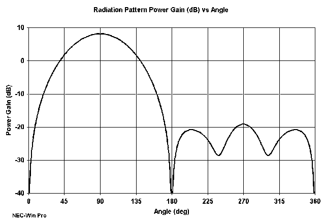
A third way to present antenna pattern data is with a standard linear
graph. Figure 9 shows the same antenna plot on a graph where the X-axis is
linearly divided into 360 degrees and the Y-axis represents the antenna's
gain. When made large enough, linear graphs can show very fine pattern
detail. However, they are to this date fairly rare in amateur literature.
So where are we so far? Actually, we have come a fairly good
distance. Although we are still in free space, we have distinguished the
common antenna pattern azimuth and elevation orientations from E-plane and
H-plane representations of the pattern. We have also compared the various
gain measures (dBi, dBd), with dBi becoming perhaps the most used measure.
We have also seen how to measure front-to-back ratio, with reference to
features on the antenna pattern. Then, we looked at three ways to present
antenna patterns, with the polar log plot being the most common.
Having looked at all these options, we shall standardize the rest of
our work. We shall use azimuth and elevation polar plots with log scaling,
and when we refer to front-to-back ratio, we shall employ the 180-degree
ratio as our general standard. We select these options not because they
are always the best ones, but because they are the ones you will encounter
most often in amateur radio antenna literature. Now we can come back to
earth.
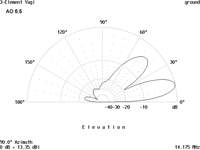
Second, notice that the pattern is elevated. Due to signal
reflections, the elevation angle of maximum radiation (also called the
Take-Off angle) is not at zero degrees. Since we are dealing with far
field patterns instead of ground waves, there is essentially no signal at
zero degrees, and antenna modeling patterns will not show line of sight
radiation in its far field patterns.
Third, notice that the forward lobe is not a line, but a lobe having a
certain vertical thickness. The common way to designate this thickness is
by measuring the number of degrees between points where the signal is
reduced in strength by 3 dB relative to its maximum strength. This figure
is called the vertical beamwidth of the antenna pattern.
For horizontally polarized antennas, such as our Yagi, the pattern of
lobes, the take-off angle of the lowest (and usually strongest) lobe, and
the vertical beamwidth will vary with the antenna height, as measured in
fractions of a wavelength. Suppose we have 2 3-element Yagis, one for 10
meters and one for 20 meters. We place the 20 meter Yagi at a height of 70
feet and the 10 meter Yagi at a height of 35 feet. Since each antenna is
at 1 wavelength height, we would expect very similar elevation patterns
from them--in fact, just the pattern shown if Figure 10.
We shall take another look at polarization of the antenna in a while,
since it make a considerable difference in antenna performance over real
ground. But first, let's get acquainted with what happens to the azimuth
pattern when we place our Yagi over real ground.
An azimuth pattern at zero degrees elevation--the horizontal
plane--will show nothing. In fact, most NEC-based programs will disallow
your attempt to take that pattern. Instead, we take azimuth patterns at
some higher angle of interest. The question now is what is interesting.
In the absence of any other considerations, most folks who present
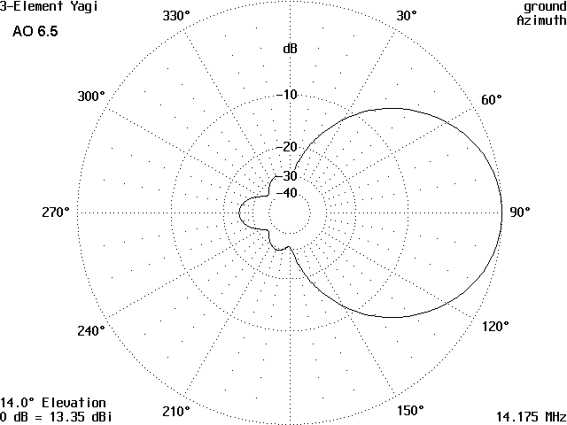
azimuth patterns over real ground do so at the take-off angle. Figure 11
is an illustration, using our handy Yagi. The pattern shape is quite
similar to the free space azimuth pattern in Figures 4-7. However, there
are some important differences.
The free space azimuth pattern was a true horizontal pattern. The
pattern over ground is a cone elevated from the horizontal by the specified
elevation angle. Since the take-off angle of this antenna is 14 degrees,
the azimuth pattern is a cone 14 degrees above the horizon. You can
picture this best by drawing a line straight across the elevation pattern
at point 14 degrees up from the horizontal on each side of the graph.
The pattern shows a front-to-back line. This ratio is not necessarily
the maximum front-to-back ratio for the antenna (although it often is).
Rather, it is the front-to-back ratio for the chosen angle (14 degrees).
Maximum front-to-back ratio (or front-to-rear) may be at some other angle.
To get an idea of where it may be--or whether it might be different enough
to be notable--simply look at the elevation pattern in the rearward
direction. Or, specify some other elevation angles for the azimuth plot.
Although the take-off angle is a handy reference point in many cases,
it may not be the most important one. Antenna builders may be more
interested in particular paths to the stations they wish to work. If we
work a lot of DX, then lower angles--perhaps in the 5 to 10 degree
range--might interest us for some paths. In these cases, the antenna
modeler and builder might show a lower angle for his or her chosen azimuth
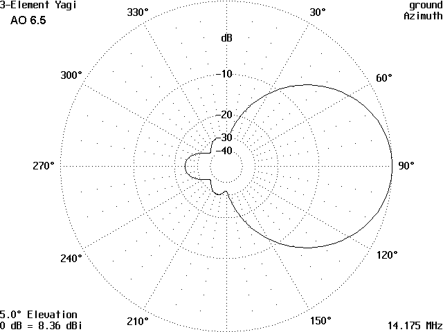
pattern. Figure 12 shows the azimuth pattern for our 1-wavelength high
Yagi at a 5 degree elevation angle. Note the reduced gain and slight
change of pattern shape. In contrast, near-vertical incidence skip is of
interest to a number of amateurs, and very high angle radiation may dictate
what azimuth pattern they choose. Hence, it pays always to 1. compare both
elevation and azimuth patterns and 2. read any accompanying text to find
out why the pattern variables were chosen.
Finally, note that the maximum gain in both our patterns over ground
is considerably greater (when taken at the take-off angle) than the same
antenna in free space. The signal reflected off the earth is not lost.
Rather, it combines with the unreflected signal. At some elevation angles,
the two are in phase and add up to a stronger signal--between 5 and 6 dB
stronger. At other angles, they are out of phase and cancel, resulting in
nulls rather than lobes. In general, for horizontal antennas, the number
of lobes counting from the ground up to a point overhead (90 degrees up) is
about 1 more than the number of wavelengths in height of the antenna.
Remembering this fact will help you both to understand antenna patterns and
to anticipate them as you read specifications in the text.
As a rule of thumb, the lobes and nulls above the horizon can be
calculated by a simple equation:
where Ae is the angle of the lobe or null, N is the lobe or null number
counting from the ground up, and h is the antenna height in wavelengths or
a fraction of a wavelength. For lobes, the value of N will be an odd
integer (1, 3, 5, 7, etc.), while for nulls, the value of N will be even
(0, 2, 4, 6, etc.). Our Yagi at a 1 wavelength height has lobes at about
14 degrees (the main lobe) and at 49 degrees. This calculation is only a
rough guide, since the exact structure of the antenna and the terrain may
alter the angles by small amounts.
In general, the ground immediately beneath and around an antenna
affects antenna efficiency and the feedpoint impedance. The far field
pattern is most affected by the quality of earth several wavelengths from
the antenna and beyond.
The quality of the ground beneath an antenna can vary from
exceptionally poor to salt-water good. Modeling software records the
quality of the earth in a composite of two figures: conductivity, which is
measured in Siemens per meter, and a dielectric constant, which has no unit
of measure. For the most part, the larger either of these figures, the
better the quality of ground. The range of possible ground conditions is
very wide. Average soil has a conductivity of 0.005 S/m with a dielectric
constant of 13. Salt water values are 5.0 S/m and 81. At the other end of
the scale, extremely poor soil found in heavy inductrial areas may show
values of 0.001 S/m and 3. Antenna handbooks usually have tables and even
maps to help to determine the quality of ground in your area.
The effect of terrain upon horizontally polarized antennas, such as
our model Yagi, tends to be slight. To see this point in action, look at
Table 1, which lists the gain and take-off angles for our model Yagi at
various heights above 3 types of ground: "Very Poor" (0.001 S/m; 5),
"Average" (0.005 S/m; 13), and "Very Good" (0.0303 S/m; 20). Note that the
take-off angles are very stable, while the gain figure increase only a
little as the ground quality increases.
We can make the same point by noting that when the E-plane of an
antenna is parallel to the earth, the effects of ground quality are
relatively small. However, if the E-plane is at right angles to the earth,
the situation changes considerably. Of course, this situation corresponds
to having a vertical antenna.
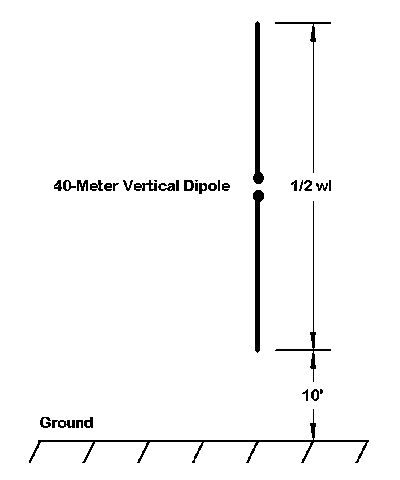
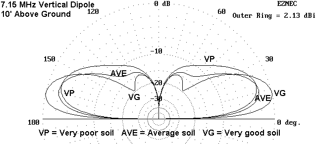
Using the same three soil types, we can take a simple vertical dipole
and illustrate the difference. In this case, I modeled a full-length
vertical dipole with the bottom 10' off the ground, as shown in Figure 13.
The resulting patterns for the three ground qualities can be combined in a
single graphic of the multiple polar plots, as shown in Figure 14. Note
that the best ground quality produces the lowest take-off angle and the
greatest signal strength, while the worst produces a weaker field strength
at a higher angle.
At the same time, notice the absence of strong higher angle lobes in
any of the three patterns in Figure 14. You will begin to see why many
operators prefer vertical antennas for DX work, especially on the lower HF
bands, where getting a horizontal antenna high enough to have a low-angle
lobe of maximum radiation is often not feasible.
These sample patterns should do more than acquaint you with the
terminology and geometry of antenna patterns. They should be the beginning
of the development of your expectations when seeing antenna plots of either
horizontal or vertical antennas.
Polarization: the Simple and the Complex
Most modeling programs from which antenna patterns emerge can show not
only the total far field of the antenna, but as well show both the
vertically polarized and horizontally polarized components of that field.
Linear antennas, such as the vertical dipole or the Yagi, tend to have
negligible radiation cross polarized to the general orientation of the
antenna. However, Many antenna types yield both types of radiation.
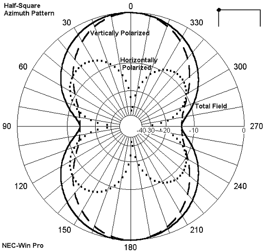
Figure 15 shows the azimuth pattern at 19 degrees elevation of a half
square, the general outlines of which have been superimposed on the plot.
Although the maximum gain of the antenna's total field is a function of the
vertically polarized radiation, the width of the field is considerably
enlarged by the presence of horizontally polarized radiation, which shows
itself in the cloverleaf pattern.
At HF, polarization becomes skewed in the ionosphere, and we normally
think of the total field as making up the effective far field. However,
for many types of loop antennas (quads, deltas, rectangles, etc.), where we
feed the antenna can make a difference in the ratio of horizontally to
vertically polarized radiation, and this, in turn can have an effect on the
overall total field of the antenna. Consider Figure 16, which shows
elevation patterns of the same delta loop. On the right, it is fed at the
center of the horizontal wire, while on the left, it is fed 1/4 wavelength
down from the triangle's apex. The patterns are significantly different,
to say the least.
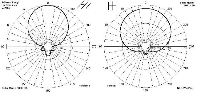
Even where antennas are linear, we should expect pattern differences
according to whether they are set up for horizontal or vertical
polarization. Consider a small Yagi for 2 meters, elevated about 30' up.
Figure 17 shows the azimuth pattern at the take-off angle for the antenna
when it is horizontal and when it is vertical. Vertically, it shows less
gain and a much wider beam width than when horizontal. If we want to
achieve a vertically polarized pattern whose shape resembles that of the
horizontal Yagi, we have to turn to a different antenna design. Despite
its higher gain, we cannot simple press the horizontal Yagi into service,
because in line-of-sight, we shall likely lose more to cross-polarization
losses than the extra gain will give us.
Now that we know how to read antenna patterns with reasonable
accuracy, let's look at some ways in which comparing antenna patterns can
assist us in understanding antennas. The following examples are only
starters, chosen for their variety. Getting a comprehensive look at
antennas is a lifetime's vocation.
1. The Center-Fed Doublet: One of the most common antennas is still
one of the most misunderstood. Because the center-fed doublet yields a
dipole-like pattern at its lowest frequency of operation, many hams believe
that it provides a dipole-like azimuth pattern at all its frequencies of
operation. Generating some azimuth patterns can tell us very quickly
whether this belief is true or false.
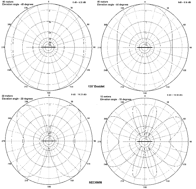
Let's make our doublet 135' long and use it from 80 meters through 10
meters. We shall make it of #14 copper wire and place it at 50' in the
air. Ignoring ground clutter and terrain variables, we would get the
patterns of Figure 18 on 80, 40, 20, and 10 meters. Notice that the
elevation angle of maximum radiation is different for each band. In fact,
on 80 meters, because the take-off angle is so high, an arbitrary angle of
45 degrees was selected for the azimuth pattern.
The antenna is 1/2 wavelength long at 80 meters, 1 wavelength long at
40 meters, etc. For your reference file, you can count the number of lobes
and relate them to the antenna length in terms of wavelengths. Also note
that as the antenna becomes longer relative to the frequency of operation,
the direction of the strongest lobes moves from a broadside direction
toward the ends of the antenna.
Besides acquainting you with the antenna patterns on various bands,
the azimuth patterns are also useful for practical antenna planning.
First, decide which bands are your favorites and, as well, which directions
from your station are best for making your most desired contacts. If you
have a choice of directions in which to string up the doublet, you can to
some measure erect the antenna for maximum signal strength on your favorite
bands in your most desired directions. The azimuth patterns can be a
useful planning tool.
2. Directional Beams and Elevation Patterns: In the maze of antenna
materials, we often find it difficult to see how antennas are related. For
example, in a number of talks I have given to beginners in ham radio,
questions have arisen about how dipoles and various size Yagis may be kin
to each other. The questioners are often surprised by how close the
relationship is.
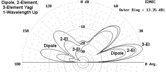
One simple demonstration I have used is to combine the elevation
patterns of a dipole, a 2-element Yagi, and a 3-element Yagi, all at the
same height. A representative version of this pattern combination appears
in Figure 19. I have added labels to the portions of the curves that might
get confusing.
From the figure, two significant features appear. First, all three
antennas have the same lobes and nulls at almost identical angles. Second,
the symmetry of the dipole pattern fore and aft of the vertical center line
disappears steadily as the parasitical elements direct the main lobe in one
direction. Hence, both kinship and differences appear at once.
Combining curves is something that an antenna modeler can do with
ease. The casual reader of amateur magazines may see only individual
patterns. However, by examining either the graphic or the text for further
information on gain, front-to-back ratio, and other features of the
antennas, one can get a pretty good view of two or more antennas in
combination. In fact, one can transpose the pattern of one antenna upon
the other for greater clarity. However, be sure that the transposed
patterns are truly comparable before transposing them.
3. Directional Beams and Azimuth Patterns: There is a myth that
pervades amateur radio: for every operating purpose whatsoever, always
choose the highest gain, highest front-to-back antenna you can afford.
Like all myths, this one has some truth, but not all truth.
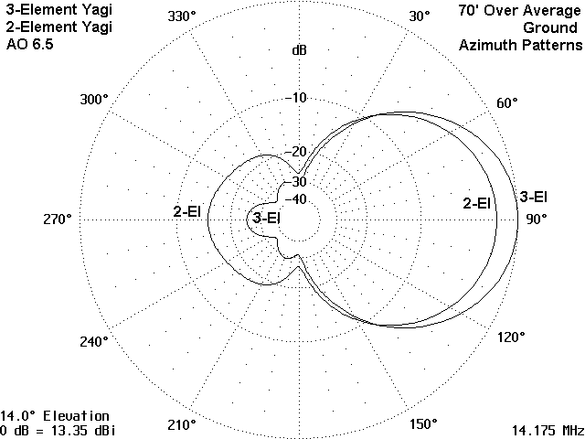
To sort out what is true and what is false in the myth, let's combine
in one graphic the azimuth patterns for a good 2-element Yagi and a good
3-element Yagi. We shall place both at 1 wavelength in height so that the
elevation angles for the patterns will be the same. The result appears in
Figure 20.
Obviously, the 3-element Yagi has superior gain and front-to-back
ratio. As such, it may indeed be the better antenna for serious DXing,
where we wish to maximize our signal to the distant receiving station and
suppress as much as possible all the potential QRM from the sides and rear
of our station. However, serious DXing is not the only important type of
amateur operating activity.
Many contesters and net operators do not want to suppress completely
signals from the sides and rear. They wish to know that someone worth
working is present, but not so loud as to interfere with the current
station being worked. Hence, they tend to prefer antennas with some
front-to-back ratio and some gain, but not the ultimate in each. For their
type of operation, the 2-element Yagi may in fact be the preferred antenna.
In this example, I have given a choice of only two antennas. However,
the basic principle can be applied to a host of antenna types. A
comparison of antenna patterns, when placed against a list of operating
goals and the needs one has to achieve those goals, can be a valuable tool
in antenna selection.
4. Truth--Pattern Shape and Pattern Detail: The shape of an antenna
pattern is not the whole story, and one can easily fall into traps of hasty
interpretation. To illustrate the point, let's look at Figure 21 and fall
into one kind of trap together.
Part A of the figure shows the free space azimuth pattern of a
2-element Yagi. The main lobe is, as expected, quite round with a good
beam width. The rear quadrant shows a very high 180-degree front-to-back
ratio. In most respect, this pattern appears to be superior to the free
space pattern shown in Part B, where the 180-degree front-to-back ratio is
under 20 dB.
Part C of the figure springs the trap. The patterns in parts A and B
are overlaid, demonstrating the far lower gain of the initial pattern. In
fact, the gain for A is only 3.8 dBi, while the gain for B is nearly 6.6
dBi. In addition, the 180-degree front-to-back ratio for B is a little
under 19 dB and is the worst case of the entire rear quadrant. By
contrast, the 29 dB 180-degree front-to-back ratio of A covers only a small
part of the rear quadrant and drops to a worst-case value of just over 16
dB.
Without the added data, we might not have realized that the
performance of the two antennas was so radically different. Even without
the pattern overlay, the data for both the forward and rear quadrants of
the antenna pattern make those differences clear. In fact, A is based on a
model of a highly loaded and shortened 10 meter beam, while B is based on a
model of a full-size 10-meter beam with phasing line connecting the two
elements.
When comparing antenna patterns, be certain that you have a complete
data set before you start the work of comparison. As we have seen, free
space patterns are not directly comparable, even though similar, to
patterns over ground. When comparing patterns taken over ground, be
certain that the heights are comparable and that the ground types are
similar. Wherever antennas are of different types, examine both the
azimuth and elevation patterns of each.
These considerations become very important when trying to make
purchase decisions among commercial beams. The manufacturers do not
present their information with a common format, and therefore, comparisons
are very difficult, even where patterns are offered. If a significant
number of manufacturers do submit antenna models to ARRL in conjunction
with its new advertising policy, then it will be much easier to
comparatively examine models of competing antennas. However, even then, we
shall have plenty of other evaluative work to do.
Antenna patterns do not tell anything like the whole story with
antennas. We have already seen the need to place the performance figures
in juxtaposition with our operating goals and needs. In addition, we shall
have to factor in such considerations as cost, weight, available space,
installation complexity, and maintenance, not to mention the legalities
which are becoming an increasing burden to antenna installation.
In the end, the information you can gain from antenna patterns will
help you make intelligent decisions about the best antenna for your station
location. When combined with all of the other types of information you can
and should gather, the more information you draw from antenna patterns, the
more satisfying your ultimate decision is likely to be.
1. The antenna patterns used to illustrate the ideas in this article are
taken from several commercial implementations of either MININEC or NEC-2,
the most frequently used antenna modeling calculation cores. The most
familiar implementations of these cores come from the following sources
(listed in alphabetical order):
Nothing in these notes should be interpreted either as an endorsement or
as a criticism of any particular software.
In addition to the commercial implementations noted above, there are
other antenna modeling software packages available, some based on the most
used cores and some based on individual or proprietary cores. Also
obtainable are some specialized output packages for specific graphical
purposes.
Updated 7-18-99. © L. B. Cebik, W4RNL. Data may be used for
personal purposes, but may not be reproduced for publication in print or
any other medium without permission of the author. An earlier version
of this items appeared in CQ (Jan. and Feb, 1999).
Variations on a Theme
Let's dwell a bit on the hypothetical Yagi in Figure 3. For the
moment, we shall consider only the free space E-plane pattern, which is the
azimuth pattern in most pattern-generating software. One of the key
dimensions you must track is the progression of angles around the perimeter
of the outer circle. To illustrate this point, consider Figure 4, Figure
5, and Figure 6. All three patterns show the same antenna model with their
lengths plotted along one axis (call it the X-axis) and their distance
apart plotted along a second axis (call it the Y-axis). The Z-axis would
represent height, either measured from the ground or--in free
space--measured above and below the plane made by the X and Y axes. We can
call this last dimension the Z-axis.
Free Space and Signal Strength
Before we come down to earth, let's consider how we determine how good
an antenna may be. There are very many dimensions to this question, but
the relevant one here is how we measure the antenna pattern. The patterns
we have looked at contain both lobes and nulls, points showing gain maxima
and minima. Figure 7 provided a list of all the lobes of the 3-element
Yagi, giving their angular direction. Figure 5 gave us information on the
main lobe (the strongest) and the side-lobe (or secondary lobe--the second
strongest). Conveniently for our exercise, this lobe was directly to the
rear of the main lobe.
Front-to-. . .: Back? Rear?
As shown in the Yagi patterns, many antennas exhibit unidirectional
patterns, that is, patterns with maximum gain in only one direction.
Unlike the bidirectional pattern of the common dipole in Figure 1, the Yagi
beam (and many other antennas) has a much higher gain in one (forward)
direction that in the other (reverse) direction. How much difference there
is between the two directions is a measure of how well the antenna may
suppress signals from the rear relative to signals from the forward
direction.
Polar Plots and Linear Graphs
The antenna patterns display so far use the most common format: the
polar logarithmic plot. The antenna is at the center of the graph, and far
field strengths are plotted in a circle for all relevant directions. In
free space, the plots for azimuth and for elevation both encompass 360
degrees. Although the outer circle can be specified at any level, most
patterns use the antenna's maximum signal in the favored direction as the
graph edge. Inner circles, as shown in Figure 4 through Figure 7,
represent lesser signal levels, measured in dB lower than the level of the
outer ring.
Down-to-Earth Reflections
An antenna over real ground changes the way in which we use antenna
patterns. Let's consider the elevation pattern first. A typical
horizontally oriented Yagi pattern is shown in Figure 10, the same one as
used in the free-space patterns of Figures 4-7. Notice that half of the
free space pattern is missing, the part that would be below ground if the
earth did not reflect antenna signals.

Does the Good Earth Make a Difference?
Most antenna patterns derived from antenna modeling software presume a
flat, uncluttered terrain for the antenna. Because we live in spaces that
may be littered with building, objects, and vegetation, and also because
our terrain, both near and far, may be anything from flat to mountainous,
model patterns only approximate the actual antenna performance we can
achieve.
                               Table 1
Gain and Take-Off Angle of a 3-Element Yagi Over Various Soil Conditions

                                 Ground Type
                    Very Poor      Average        Very Good
                 (C=0.001/DC=5) (C=0.005/DC=13) (C=0.0303/DC=20)

Antenna Height    Gain (dBi)/    Gain (dBi)/    Gain (dBi)/
(Wavelengths)         TO angle       TO angle       TO angle

0.50 wl             11.7 / 24      12.3 / 25      12.8 / 26

0.75 wl             12.6 / 17      13.1 / 18      13.4 / 18

1.00 wl             13.0 / 13      13.4 / 14      13.7 / 14

1.25 wl             13.2 / 11      13.6 / 11      13.8 / 11

1.50 wl             13.4 /  9      13.7 /  9      13.9 /  9

1.75 wl             13.5 /  8      13.7 /  8      13.9 /  8

2.00 wl             13.6 /  7      13.8 /  7      14.0 /  7

Note:  The model used for these representative values is aluminum and the
check frequency is 14.175.  As always, modeling is done over flat terrain
and does not account for terrain variations.  C is conductivity as measured
in S/m; DC is a dielectric constant and has no units.  TO angle is the
elevation angle of maximum radiation and is in degrees above the horizon.

Table 1:  Representative values for gain and take-off angle of a 3-element
Yagi over various soil conditions.

Comparisons, Both Educational and Practical

In the End, There is No End
We have barely scratched the surface of the things we can learn from
antenna patterns, when we learn to read them accurately and carefully. By
examining the azimuth and elevation patterns for single antennas, we can
gauge their performance in terms of gain, front-to-back specifications,
lobes and nulls, beam width, and polarization composition. We can also
compare antennas, both within a single type and among types, analyzing high
and low angle lobes, lobe direction and shape, and numerous other
properties.
Notes
![]()
![]()
![]() Go to Main Index
Go to Main Index