 Horizontal Phased Arrays with Parasitic Directors
2-element phased arrays can be set up for maximum gain or for maximum 180- degree front-to-back ratio. The latter set-up is the norm for phased verticals, but does not yield maximum gain. Indeed, for most horizontal 2- element arrays, maximizing the rear null results in gain that equals or is less than that of a 2-element Yagi (which has only a modest front-to-back ratio).
Maximizing gain results in about an extra dB of gain relative to the maximum rear null configuration. However, the front-to-back ratio goes to pot, dropping easily to under 10 dB.
Note that all of this is done without changing the antenna dimensions. Although Yagis require a certain geometry to achieve either maximum gain or maximum rear null, phased arrays achieve the same results by setting the relative current magnitude and phase on the two elements. If we use networks to set the individual current magnitudes and phases, we may use equal element lengths of approximately 1/2 wl.
The norm is to use transmission line lengths to set the relative current magnitudes and phases, and this practice sets limits to what is possible. Since we have only a few types of available commercially made transmission lines, using them restricts design variations. We may also make our own lines, but in most cases, they will have too high a characteristic impedance to handle linear dipole-style elements and are better suited for use with folded dipoles.
To compensate for restrictions in the feasible limits of setting current magnitudes and phases with transmission lines, we often alter the geometry of the elements to achieve a given result. For maximum rear null configurations, the rear element may actually be shorter by a small amount than the forward element in some cases.
However, practical design rarely chooses either the maximum gain (too little front-to-back ratio) or the maximum rear null (too little gain) configurations. Intermediate values are the general rule and result in gains up to about 1/2 dB greater than with a 2-element Yagi of equal spacing while keeping the front-to-back ratio in the 18-20 dB ballpark. Such phased arrays tend to have the appearance of a 2-element Yagi with a low impedance connecting cable between the two elements.
For further work on the fundamentals of 2-element horizontal phased arrays, see "Modeling and Understanding Small Beams: Part 5: The ZL Special," Communications Quarterly (Winter, 1997), pp. 72-90

The sketch makes the antenna appear to be a 2-element phased array with a director ahead. Appearances do not deceive. This experimental antenna for 24.95 MHz uses a 14' boom (roughly comparable to 12' at 10 meters or 24' at 20 meters). This is considered a long boom for a 3-element Yagi but a short boom for a 4-element Yagi. Dimensions appear in the figure. Models of the antenna use 3/4" diameter aluminum. The phasing line is a 6.6' length of RG-8 (velocity factor 0.66) or equivalent. Connections are reversed, since the required current phasing is that of a -45-degree line, not that of a +135-degree line. (Although impedance goes through two cycles per 360 degrees of transmission line, voltage and current go through but 1 cycle in the same length. A short half-twist line thus cannot effect a 135-degree current transition directly, but accomplishes the equivalent by a reversal of both voltage and current phase, but must always count backwards from zero in accounting for the current magnitude and phase in the line.)
Using coax as the phase line calls for special precautions due to the reversal. Proximity to metal booms can disrupt the characteristic impedance of the line due to external couplings. Hence, spacing the line from the boom is necessary. (Early ZL-Special builders often forgot this and taped the phased line to the metal boom, resulting in disappointing performance.)

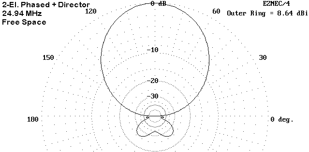
The antenna performance is quite remarkable and quite even across narrow bands like 12 meters. As Figure 2 notes, the maximum free-space gain is over 8.6 dBi, with a 180-degree front-to-back ratio approaching 34 dB.
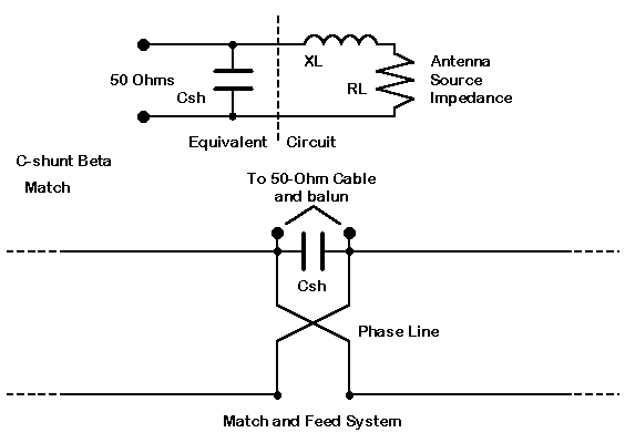
Feeding the antenna is a bit of a challenge, since the feedpoint impedance is about 15.5 + j23.0 Ohms. However, we can use a little-appreciated version of the beta match. The beta match is simply an L-network, where the series reactance is part of the antenna feedpoint impedance in series with the resistive component. If the reactance is correct, we can simply add a shunt reactance of the opposite type across the terminals to effect an impedance transformation to 50 Ohms. See Figure 3.

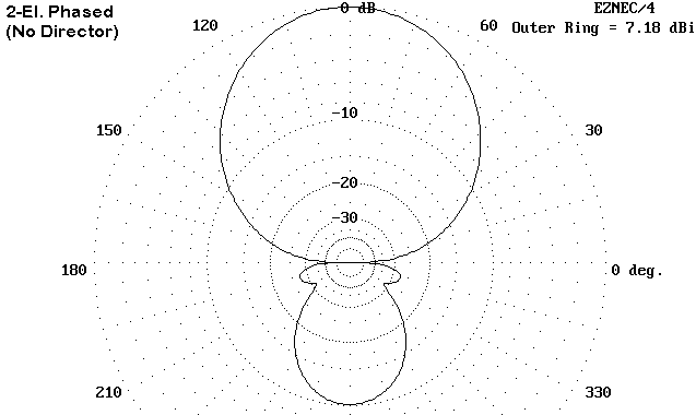
Since the series reactance of the antenna feedpoint is inductive, the shunt reactance must be capacitive. The required reactance value is about 35 Ohms, which translates into a capacitance of about 180 pF for 12 meters. Since there will be construction variables in every antenna, a variable capacitor should be used to establish the exact value required for a good coax match. Replace the variable with an equivalent fixed capacitor of the nearest value. Be certain that it has substantial internal and external lead size to handle the high currents at the feedpoint. Because of the low antenna source impedance, ensure that all connections are very tight electrically. Weather seal the capacitor and its connections. Use a choke balun between the matching section and the main coax cable. The director essentially controls both the gain and the front-to-back ratio of the array. (In Yagi design of greater than 2 elements, the reflector largely controls the driver impedance, with the director having the greater effect upon both gain and front-to-back ratio.) We can easily glimpse this fact by stripping away the director and checking the performance of the 2 phased elements.

As Figure 4 shows, the correct design of the 2-element phased array portion of the total antenna is to set it for maximum gain, in this case, a native free-space value approaching 7.2 dBi. The front-to-ratio is about 10 dB, mediocre at best.
Adding the director yields an additional gain of about 1.4 dB. Moreover, the front-to-back ratio improves by over 20 dB. Had the original phased 2- element section been set for maximum rear null, the final performance figures would not have been obtained.
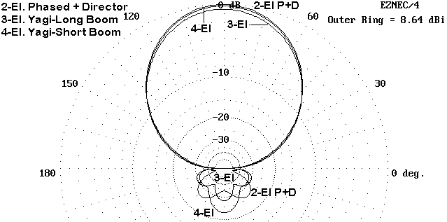
The 3-element design uses a boom length less than a foot shorter than our array. However, its gain is limited to about 8.1 to 8.15 dBi in free space if it is to sustain a front-to-back ratio above 20 dB. The feedpoint impedance is just about 25 Ohms when resonant.
The 4-element Yagi uses a boom less than a foot longer than our array. Its gain approaches that of the array, being about 0.2 dB less. The front-to- back ratio is in the same ball park. The feedpoint impedance is midway between our array and the 3-element Yagi. However, this performance is purchased at the cost of an added element.

Figure 5 tells the same story graphically. Phased arrays with parasitical directors can yield exceptional performance relative to wholly parasitical antenna designs with the same boom length and number of elements.
Not all designs calling themselves phased arrays with directors are true 3- element designs. Some multiband designs use "log" cells for drivers on multiple bands or multiple parts of bands. The crossed lines work, but not as either contributors to gain or to rear nulling.
However, these brief notes only hint of work to be done. The phased array portion of the antenna has not been optimized for the source impedance. Whether the performance of this design can be sustained at a higher and more desirable source impedance is not known to me at this time. Whether the added gain of the 3-element array carries over into 4 and 5 element versions is also not known to me at this time.
This very preliminary work was done without reference to any commercial
antenna. Unfortunately, I do not have on file any detailed design plans of
antennas claiming to use or actually using these principles. In the end,
these unknowns suggest that the phased array plus director(s) is a design
worth further investigation as time permits.
8-27-98. © L. B. Cebik, W4RNL. Data may be used for
personal purposes, but may not be reproduced for publication in print or
any other medium without permission of the author.