 Series Matching: A Review
When the load impedance of an antenna does not match the characteristic impedance of the transmission line feeding the antenna, we often wish to effect a match. Similarly, where we wish to shift from one kind of transmission line to another having a different characteristic impedance, we must also effect a match. The are numerous means of obtaining matching conditions including (with deference to the limitations of each) an L-C network, a standard transformer, and a transmission-line transformer (balun). Often overlooked in the search for a matching system is the "series-section" transformer or series matching system.
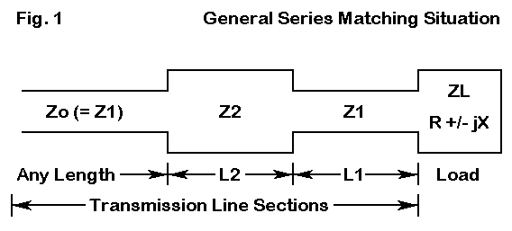
A series matching system consists of several elements: a load impedance (Zl), a characteristic impedance of a line to be match to the load (Zo), and up to two lengths of transmission line constituting the impedance transformer to effect a match between the load impedance and the line impedance. The transmission line(s) used to effect the match can be specified in terms of their characteristic impedances, which we may call Z1 and Z2, where Z1 is always the section closest to the load. Figure 1 sketches the typical series matching situation.

The advantages of using a series matching system are many. First, for almost any set of conditions, one can find commercially made transmission lines to serve as the elements of the system. Second, losses are generally low because the required lengths for Z1 and Z2 are short. Third, connections between the line lengths can be made with standard commercial connectors. We can weatherproof these connectors by standard means. The result is that we can avoid using fixed and variable lumped components (coils and capacitors) to create the impedance transformation, components which are often more difficult to weatherproof.
The key limitation to all series section matching systems is that they are frequency specific. Since all are composed of lengths of transmission line that will be specified in electrical degrees, the physical length of the lines will vary with frequency. In most cases, the effective operating bandwidth of these systems will be quite sufficient to cover any of the ham bands (at least above 80 meters). However, they are not broad-banded systems in the sense that a well-designed impedance-transforming balun or unun is broad-banded.
One way to get a handle on series matching systems and their utility is to do a little history, but only as far back as 1961. Depending on the age of the reader, those 37 years may seem like a very long time or only yesterday.

He recognized that other matching systems, some of them falling into the series category, were available, such as impedance tapering line sections, single and multiple quarter-wavelength transformer sections, and slug and stub matching techniques. (Balun and unun techniques were not well- developed in 1961, although--as Sevick has shown in his several books and many articles--the principles were available.) However, all of these methods required special materials besides the two line types to be joined.
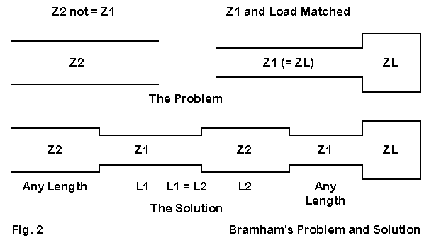
Note the special conditions that apply to Bramham's problem. The connection is between two types of transmission line. The initial line is presumed to be matched to the load so that the VSWR is 1:1. Hence, the impedances in question are resistive, with no significant reactive component.
Bramham's solution was to develop a means for calculating equal lengths of the two lines, Z1 and Z2, that would effect the impedance transformation for a given frequency. The solution is elegantly simple. First, let's define a special term, M

where Z1 and Z2 are the values of the two lines to be joined in the scheme shown in Figure 2.
The only question is how long to make the two equal section of line inserted between the line to the load and the line to the source. The answer is available on a calculator:

where L1 is the length if the matching line Z1 and L2 is the length of the matching line Z2. I have transposed Bramham's equation to the "tan" form useful with calculators, although his original was expressed as a "cot" equation.
The answers will be given in either degrees or radians, depending on how you set your calculator. If you wish the answer as a fraction of a wavelength, divide the answer in degrees by 360 and the answer in radians by 2pi. Multiply that figure by a wavelength at the frequency of interest, and you have the required line lengths with a velocity factor of 1.0. You can then multiply each line length by the relevant velocity factor for that line to reach the final line lengths to be used.
The line lengths will never exceed 30 degrees (1/12 of a wavelength) each, which represents the limiting case of the two lines approaching the same impedance. The operating bandwidth of the system is almost equal to that of a single quarter wavelength matching system and is widest where the two lines are closest in characteristic impedance. However, unlike the quarter wavelength system, which often cannot be implemented because a suitable intermediate impedance line does not exist, the Bramham system can always be implemented where the load matches the initial line. Moreover, it can be implemented at any convenient point down the initial line and need not be placed at the terminals of the load.
The applications are obvious. For example, one might run surplus 75-Ohm hard line from the shack to a tower. At an convenient point at either end, one may use a Bramham series section transformer to effect a match to 50-Ohm cable to be run at one end into the shack and at the other up the tower or around the rotator to the antenna. However, this technique would apply only to a monoband installation. VHF adaptations of the same technique are obvious.
As is often the case, someone can come along and show a given matching technique to be a special case of a more general solution. Such was the fate of the Bramham series transformer section.

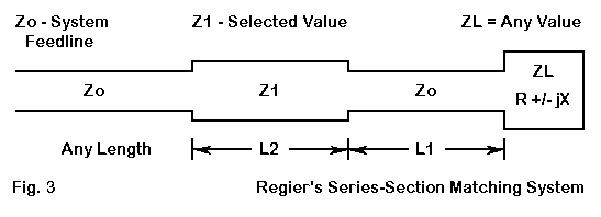
Taking any load that is not matched to a desired feed line, we may attach a specific length of the desired feedline. That specific length will transform the impedance to another value. That value will, in turn, be transformed by the second line of a certain characteristic impedance to a value that is a match with the desired system feedline. The two lengths of line for the series matching sections depend on frequency, and the solution is frequency specific with a certain operating band width. The lengths are also dependent on the characteristic impedance selected for the special section of line.
The details of Regier's solution can be found in the following references:
I list these important references in the text rather than in a footnote because experience has taught me that most folks simply pass over footnotes. These items are too important to the subject to ignore. A summary of Regier's work is available in almost any edition of The ARRL Antenna Book. In the 18th Edition, the basic information appears on pages 26-4 ff. Those interested in design series section transformers with the aid of Smith Charts should see pages 28-12 ff or the QST article.
Regier's solution is best used in "normalized" form, where the ratios of one impedance to another are first reduced to single values. Otherwise, the calculation equations tend to look terribly opaque. So let's define a few quantities.

where the load impedance is specified as RL +/- jXL and Z1 is the selected impedance of the special matching section. Note that we shall let L1 be the electrical length in degrees of the line Zo between the load and the special matching section, while L2 is the electrical length in degrees of the special matching section.
Now we can calculate the two lengths, starting with L2, since it plays a role in calculating L1.

Although this equation looks a bit forbidding, it can be handled on a calculator. The equation produces two good results, plus and minus. The positive result gives a shorter length for L1 and hence is preferred. If the result is an imaginary number, then the value of n must be changed. You can do this by increasing the value of Z1, the characteristic impedance of the special matching section. Remember that the series matching technique can use parallel transmission line sections as well as coaxial cables, so using a length of 300-Ohm or 450-Ohm line as the special matching section is perfectly appropriate.
Now let's turn to L1.

In some cases, a calculator will return a negative value for the electrical length of L1. To arrive at the correct positive value, simply add 180 degrees to the calculated result. For example, should L2 return a value of -62 degrees, the correct result will be 118 degrees.
Since the lengths L1 and L2 are in electrical degrees, divide them by 360 to arrive at a fraction of a wavelength. Then, for the frequency of interest, multiply the fraction times a wavelength for a set of physical lengths with a velocity factor of 1.0. Finally, for the lines actually to be used, multiply each physical length by the velocity factor of actual line, and arrive at the actual line lengths.
For those who shy away from math, Regier's equations appear to be too complex for the average ham to use. Taking this viewpoint leads the builder often to miss a simple and useful load-to-line matching procedure for monoband antennas. To make the Regier series-section equations more accessible to every ham, they are available as one of the utility programs available in the HAMCALC collection. HAMCALC's most recent version (which has updated the series-section program to include common parallel lines) is available from George Murphy, VE3ERP, 77 McKenzie Street, Orillia, ON L3V 6A6, Canada. Murph asks for $5 to cover the cost of disks, mailers, and postage, and he contributes the excess of income over costs to the Canadian National Institute for the Blind amateur radio program.
Likewise, the Bramham alternating section system is also a special case of the Regier solution. If you examine the equations, first let x go to zero, since the Bramham system presumes a matched load with no reactance. Then n and r become equal, since the load or the line to the load has the same impedance value as the characteristic impedance of the special matching section.
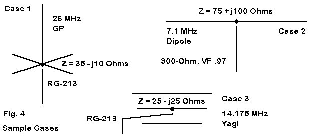
Unlike the Bramham system, the Regier series matching system permits matching to many type of loads, with or without a reactive component. Let's take a look at a few sample cases, as sketched in Figure 4.

Our first antenna is a ground plane antenna cut for 28 MHz and fed with 50- Ohm RG-213 coaxial cable. The antenna presents a source impedance of 35 - j10 Ohms. Although we might live with the natural VSWR of the antenna, we are artificially reducing the 2:1 VSWR bandwidth, because the lowest value is nearly 1.5:1. To achieve a lower minimum SWR value, we can introduce a series matching system consisting of a 141.8-degree length of our main cable (9.09') connected to the antenna. Follow this with a 28.6-degree length of RG-11 (1.84'). Finally, return to the main RG-213 cable to the shack. The main cable sees, at the design frequency, a 50-Ohm resistive impedance.
Case 2 consists of a wire dipole cut for 7.1 MHz and presenting a feedpoint impedance of 75 + j100 Ohms. The 300-Ohm feedline presents a very high value of VSWR. We can overcome this high SWR, if we use a 1.48-degree length of the 300-Ohm line (0.55' at a velocity factor of 0.97) from the antenna, followed by a 25.1-degree length of 75-Ohm RG-11 (6.35'), and return to our 300-Ohm line, the line to the shack sees a 1:1 SWR at the design frequency.
All of these Regier calculations can not only be verified by measurements of actual antenna-cable systems, they can also be modeled on NEC using the TL facility as a pre-construction cross-check on the initial calculations.
Our final example is a 14,175 MHz Yagi that presents a source impedance of 25 - j25 Ohms. Such antennas often use beta-match systems to arrive at a match with a 50-Ohm feedline. As an alternative, we can also use a Regier series matching system consisting of a 153.3-degree length (19.4') of RG- 213 from the antenna, followed by a 6.4-degree length of 450-Ohm parallel line (1.2' at if VF = 0.97), before returning to the RG-213 that goes to the shack. The line to the shack sees a 50-Ohm load at the junction with the parallel section. This case uses the high-impedance line for the special section because the minimum characteristic impedance that would satisfy the calculations is 80 Ohms for higher Zo matching sections. Although there are 92-Ohm coaxial cables, the 450-Ohm line is easily made from shop scrap and works just as well with a shorter length. (If a choke balun to block common mode currents from the main feedline is to be used, it should be installed on the shack side of the special section. The higher SWR and mismatch along the first two sections of cable may not be suitable for some types of choke balun designs.)
Alternatively, as pointed out to me by Roger Johnson, N1RJ, one might use a parallel run of RG-213 for the matching section, giving 25 Ohms for a lower Zo matching section. In this solution, the initial single RG-213 would be 6.5' long (51.3 degrees), followed by a 4.3' 25-Ohm section (33.7 degrees) and finally the main RG-213 line to the shack. For almost all cases, there are multiple solutions, which fact allows you to select from a reasonable range of lines to achieve the electrical and mechanical goals of your matching challenge.
Additional monoband applications for Regier series-section matches abound, especially at VHF, where antennas are normally monoband affairs. For example, in stacked arrays of odd numbers of antennas, it is often not possible to arrive at reasonably low-loss values of impedance through 1/4 wavelength matching sections that then combine in parallel to yield a central 50-Ohm feed system. Using series matching-sections may well permit arriving at a junction of three 150-Ohm impedances, which then combine to yield the desired 50-Ohm feed. Equally, it is possible to arrive at a value for each line of 210 Ohms so that they then combine to match a 70-Ohm surplus low-loss hard line directly, without need for further matching.
A utility program, such as the one included in the HAMCALC collection, makes it easy to run through innumerable combinations in quick order and then to devote most of your time selecting the one offering the best performance. Performance might in some cases be a measure of VSWR operating band width. In other cases, it might be a matter of total system cable losses (which can be checked on a program such as TLA by N6BV, available without cost via ARRL.
The series-section matching system deserves addition to any antenna builders repertoire of methods for matching loads to feedlines.
Updated 2-5-99, 4-4-99. © L. B. Cebik, W4RNL. This item first appeared in AntenneX, Jan., 1999. Data may be used for personal purposes, but may not be reproduced for publication in print or any other medium without permission of the author.