
 So You Want to Build Your Own LPDA
Considerable interest persists in the Telerana, a very light-weight wire LPDA with elements bent forward into Vees. The original design emerged from work by George Smith, W4AEO, and Ansyl Eckols, YV5DLT. The design first appeared in QST for July, 1981 and has been in most editions of The ARRL Antenna Book since that time (pp. 10-13 to 10-16 in the 18th Edition). A modified hybrid, consisting of the basic Telerana with parasitic reflectors, by Markus Hansen, VE7CA, appeared on Volume 4 of The ARRL Antenna Compendium (pp. 112-117).
The Telerana begins as a standard-design 13-element LPDA with a Tau of 0.9 and a Sigma of 0.05. It presents us with the opportunity to analyze two facets of LPDA design: 1. the advantages or disadvantages of using Vee-shape elements and 2. the advantages or disadvantages of using small diameter wire in contrast to large tubular elements. We shall look only at the original design in what follows, since the topic of LPDA-parasitic hybrids is a subject all its own. By sticking to the pure LPDA design, the results will be comparable to those drawn out of models in Parts 1 and 2 of this sequence.
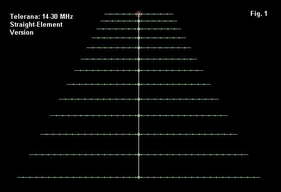
The design specifies a 400-Ohm inter-element phasing line, with a 200-Ohm design feedpoint impedance. In the model, each element is assigned an odd number of segments so that the TL-facility transmission line will be centered on each element. Segment numbers were assigned by giving the shortest element 11 segments and increasing that number for longer elements by the inverse of Tau (1.11) and rounding to the nearest odd number. This technique ensures that the longest element will have a sufficient number of segments at the highest frequency (30 MHz) used by the antenna.
For reference, here is the antenna model description.
Telerana-Ant Bk 10-13: Straight Elements          Frequency = 14  MHz.

Wire Loss: Copper -- Resistivity = 1.74E-08 ohm-m, Rel. Perm. = 1

              --------------- WIRES ---------------

Wire Conn.--- End 1 (x,y,z : ft)  Conn.--- End 2 (x,y,z : ft)  Dia(in) Segs

1          0.000,-20.330,  0.000         0.000, 20.330,  0.000    # 14   39
2          4.060,-18.300,  0.000         4.060, 18.300,  0.000    # 14   35
3          7.710,-16.460,  0.000         7.710, 16.460,  0.000    # 14   31
4         11.020,-14.820,  0.000        11.020, 14.820,  0.000    # 14   29
5         13.970,-13.310,  0.000        13.970, 13.310,  0.000    # 14   25
6         16.630,-12.000,  0.000        16.630, 12.000,  0.000    # 14   23
7         19.050,-10.790,  0.000        19.050, 10.790,  0.000    # 14   21
8         21.140, -9.710,  0.000        21.140,  9.710,  0.000    # 14   19
9         23.150, -8.720,  0.000        23.150,  8.720,  0.000    # 14   17
10        24.890, -7.870,  0.000        24.890,  7.870,  0.000    # 14   15
11        26.470, -7.080,  0.000        26.460,  7.080,  0.000    # 14   13
12        27.890, -6.360,  0.000        27.890,  6.360,  0.000    # 14   13
13        29.160, -5.740,  0.000        29.160,  5.740,  0.000    # 14   11

              -------------- SOURCES --------------

Source    Wire      Wire #/Pct From End 1    Ampl.(V, A)  Phase(Deg.)  Type
          Seg.     Actual      (Specified)

1           6    13 / 50.00   ( 13 / 50.00)      1.000       0.000       V

No loads specified

                -------- TRANSMISSION LINES ---------

Line  Wire #/% From End 1   Wire #/% From End 1    Length     Z0   Vel Rev/
      Actual  (Specified)   Actual  (Specified)              Ohms Fact Norm

1    1/50.0  (  1/50.0)    2/50.0  (  2/50.0)  Actual dist  400.0  1.00  R
2    2/50.0  (  2/50.0)    3/50.0  (  3/50.0)  Actual dist  400.0  1.00  R
3    3/50.0  (  3/50.0)    4/50.0  (  4/50.0)  Actual dist  400.0  1.00  R
4    4/50.0  (  4/50.0)    5/50.0  (  5/50.0)  Actual dist  400.0  1.00  R
5    5/50.0  (  5/50.0)    6/50.0  (  6/50.0)  Actual dist  400.0  1.00  R
6    6/50.0  (  6/50.0)    7/50.0  (  7/50.0)  Actual dist  400.0  1.00  R
7    7/50.0  (  7/50.0)    8/50.0  (  8/50.0)  Actual dist  400.0  1.00  R
8    8/50.0  (  8/50.0)    9/50.0  (  9/50.0)  Actual dist  400.0  1.00  R
9    9/50.0  (  9/50.0)   10/50.0  ( 10/50.0)  Actual dist  400.0  1.00  R
10  10/50.0  ( 10/50.0)   11/50.0  ( 11/50.0)  Actual dist  400.0  1.00  R
11  11/50.0  ( 11/50.0)   12/50.0  ( 12/50.0)  Actual dist  400.0  1.00  R
12  12/50.0  ( 12/50.0)   13/50.0  ( 13/50.0)  Actual dist  400.0  1.00  R

Ground type is Free Space
Note that no stub is used with this design, and none of the compensation techniques noted in Part 2 of this sequence has been applied. No stub is needed because the high characteristic impedance of the phasing line tends to suppress harmonic operation of rear elements on the upper frequencies. The absence of compensation techniques was a design choice by the originators of the Telerana.
Transforming the antenna into one with elements that form forward Vees requires considerable care. The outline of the model appears in Fig. 2.
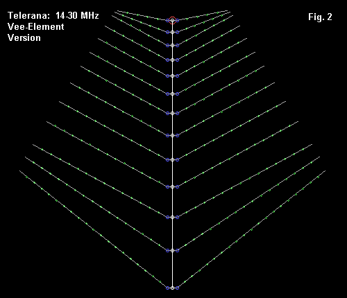
The segmentation of the straight-element model yielded a segment length of just about 1 foot. To ensure that the TL transmission line in NEC would be centered on each element, I created a 1-segment, 1-foot wire at each element position. The outer portions of each element were segmented in approximate 1-foot lengths and then bent forward at the appropriate angle. Let's count elements from the longest (#1) to the shortest (#13).
Elements #2 through #11 are bent forward about 30 degrees on each side, relative to an equivalent straight element. Element #1 is bent forward by about 45 degrees, while elements #12 and #12 are bent forward about 22 degrees and 12 degrees, respectively. The angle changes for these elements is a function of fitting the elements within the framework specifically design for the antenna. The resulting antenna is longer (30.3') but narrower than the straight-element model.
For reference, here is the model description.
Telerana-Ant Bk 10-13: Vee                Frequency = 14  MHz.

Wire Loss: Copper -- Resistivity = 1.74E-08 ohm-m, Rel. Perm. = 1

              --------------- WIRES ---------------

Wire Conn.--- End 1 (x,y,z : ft)  Conn.--- End 2 (x,y,z : ft)  Dia(in) Segs

1         12.746,-15.691,  0.000  W2E1   0.000, -0.500,  0.000    # 14   20
2   W1E2   0.000, -0.500,  0.000  W3E1   0.000,  0.500,  0.000    # 14    1
3   W2E2   0.000,  0.500,  0.000        12.746, 15.691,  0.000    # 14   20
4         14.270,-15.081,  0.000  W5E1   4.060, -0.500,  0.000    # 14   17
5   W4E2   4.060, -0.500,  0.000  W6E1   4.060,  0.500,  0.000    # 14    1
6   W5E2   4.060,  0.500,  0.000        14.270, 15.081,  0.000    # 14   17
7         15.690,-14.322,  0.000  W8E1   7.710, -0.500,  0.000    # 14   15
8   W7E2   7.710, -0.500,  0.000  W9E1   7.710,  0.500,  0.000    # 14    1
9   W8E2   7.710,  0.500,  0.000        15.690, 14.322,  0.000    # 14   15
10        18.180,-12.901,  0.000 W11E1  11.020, -0.500,  0.000    # 14   14
11 W10E2  11.020, -0.500,  0.000 W12E1  11.020,  0.500,  0.000    # 14    1
12 W11E2  11.020,  0.500,  0.000        18.180, 12.901,  0.000    # 14   14
13        20.375,-11.594,  0.000 W14E1  13.970, -0.500,  0.000    # 14   12
14 W13E2  13.970, -0.500,  0.000 W15E1  13.970,  0.500,  0.000    # 14    1
15 W14E2  13.970,  0.500,  0.000        20.375, 11.594,  0.000    # 14   12
16        22.380,-10.459,  0.000 W17E1  16.630, -0.500,  0.000    # 14   11
17 W16E2  16.630, -0.500,  0.000 W18E1  16.630,  0.500,  0.000    # 14    1
18 W17E2  16.630,  0.500,  0.000        22.380, 10.459,  0.000    # 14   11
19        24.195, -9.411,  0.000 W20E1  19.050, -0.500,  0.000    # 14   10
20 W19E2  19.050, -0.500,  0.000 W21E1  19.050,  0.500,  0.000    # 14    1
21 W20E2  19.050,  0.500,  0.000        24.195,  9.411,  0.000    # 14   10
22        25.745, -8.476,  0.000 W23E1  21.140, -0.500,  0.000    # 14    9
23 W22E2  21.140, -0.500,  0.000 W24E1  21.140,  0.500,  0.000    # 14    1
24 W23E2  21.140,  0.500,  0.000        25.745,  8.476,  0.000    # 14    9
25        27.260, -7.619,  0.000 W26E1  23.150, -0.500,  0.000    # 14    8
26 W25E2  23.150, -0.500,  0.000 W27E1  23.150,  0.500,  0.000    # 14    1
27 W26E2  23.150,  0.500,  0.000        27.260,  7.619,  0.000    # 14    8
28        28.575, -6.883,  0.000 W29E1  24.890, -0.500,  0.000    # 14    7
29 W28E2  24.890, -0.500,  0.000 W30E1  24.890,  0.500,  0.000    # 14    1
30 W29E2  24.890,  0.500,  0.000        28.575,  6.883,  0.000    # 14    7
31        29.760, -6.198,  0.000 W32E1  26.470, -0.500,  0.000    # 14    6
32 W31E2  26.470, -0.500,  0.000 W33E1  26.470,  0.500,  0.000    # 14    1
33 W32E2  26.470,  0.500,  0.000        29.751,  6.203,  0.000    # 14    6
34        30.085, -5.933,  0.000 W35E1  27.890, -0.500,  0.000    # 14    6
35 W34E2  27.890, -0.500,  0.000 W36E1  27.890,  0.500,  0.000    # 14    1
36 W35E2  27.890,  0.500,  0.000        30.085,  5.933,  0.000    # 14    6
37        30.249, -5.625,  0.000 W38E1  29.160, -0.500,  0.000    # 14    5
38 W37E2  29.160, -0.500,  0.000 W39E1  29.160,  0.500,  0.000    # 14    1
39 W38E2  29.160,  0.500,  0.000        30.249,  5.625,  0.000    # 14    5

              -------------- SOURCES --------------

Source    Wire      Wire #/Pct From End 1    Ampl.(V, A)  Phase(Deg.)  Type
          Seg.     Actual      (Specified)

1           1    38 / 50.00   ( 38 / 50.00)      1.000       0.000       V

No loads specified

                -------- TRANSMISSION LINES ---------

Line  Wire #/% From End 1   Wire #/% From End 1    Length     Z0   Vel Rev/
      Actual  (Specified)   Actual  (Specified)              Ohms Fact Norm

1    2/50.0  (  2/50.0)    5/50.0  (  5/50.0)  Actual dist  400.0  1.00  R
2    5/50.0  (  5/50.0)    8/50.0  (  8/50.0)  Actual dist  400.0  1.00  R
3    8/50.0  (  8/50.0)   11/50.0  ( 11/50.0)  Actual dist  400.0  1.00  R
4   11/50.0  ( 11/50.0)   14/50.0  ( 14/50.0)  Actual dist  400.0  1.00  R
5   14/50.0  ( 14/50.0)   17/50.0  ( 17/50.0)  Actual dist  400.0  1.00  R
6   17/50.0  ( 17/50.0)   20/50.0  ( 20/50.0)  Actual dist  400.0  1.00  R
7   20/50.0  ( 20/50.0)   23/50.0  ( 23/50.0)  Actual dist  400.0  1.00  R
8   23/50.0  ( 23/50.0)   26/50.0  ( 26/50.0)  Actual dist  400.0  1.00  R
9   26/50.0  ( 26/50.0)   29/50.0  ( 29/50.0)  Actual dist  400.0  1.00  R
10  29/50.0  ( 29/50.0)   32/50.0  ( 32/50.0)  Actual dist  400.0  1.00  R
11  32/50.0  ( 32/50.0)   35/50.0  ( 35/50.0)  Actual dist  400.0  1.00  R
12  35/50.0  ( 35/50.0)   38/50.0  ( 38/50.0)  Actual dist  400.0  1.00  R

Ground type is Free Space
The number of wires increases, but the total number of segments remains about the same as with the straight-line model. The phasing line remains the same as in the other model.
Both models were checked within each of the 5 ham bands between the 14 to 30 MHz design passband for the antenna. Modeling was done on NEC-4, but NEC-2 would be entirely satisfactory, since neither model presses any limitation in either program. The only limitation applies to both programs and both models: the mathematical phasing line does not show wire losses, although these would be minimal. Be intention, the velocity factor of the phasing line has been set at 1.0.
Both antennas have feedpoint impedance that fall generally within the design figures for a 2:1 SWR relative to 200 Ohms. The simplest way to show the relative performance between the Vee and straight element models is a simple table of gain and front-to-back ratios. A single frequency was used for 17 and 12 meters, but on 20 and 15 meters, band-edge and band-center values are shown. For 10 meters, the values cover 0.5 MHz intervals from 28 to 30 MHz.
Frequency           Free-Space Gain (dBi)         Front-to-Back Ratio (dB)
   MHz              Straight       Vee            Straight       Vee
14.0                5.71           4.50           11.63           7.53
14.175              5.71           4.54           11.69           7.73
14.35               5.72           4.58           11.79           7.92

18.12               6.08           5.21           15.85          11.16

21.0                6.26           5.40           16.70          12.17
21.225              6.24           5.38           16.70          12.16
21.45               6.21           5.36           16.92          12.13

24.95               6.13           5.18           18.16          12.75

28.0                5.93           5.14           18.23          13.06
28.5                5.86           5.11           17.77          12.74
29.0                5.81           5.08           17.31          12.39
29.5                5.79           5.05           16.87          12.04
30.0                5.80           5.03           16.48          11.75
If we select the center-point of each band and average the gain values and the front-to-back values, we obtain 5.99 dBi and 15.94 dB for the straight-element model and 5.08 dBi and 11.24 dB for the true Telerana with Vee elements. The straight line model is almost a full dB higher in gain and over 3.5 dB better in front-to-back ratio. These values are not unusual for arrays using elements near 1/2 wl long, whether LPDA or parasitic in design.
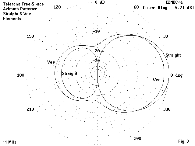
Fig. 3 overlays the free-space azimuth patterns for the straight-element and the Vee model at 14 MHz. It demonstrates some of the reasons why Vee-ed elements have a lower forward gain. Not only does the Vee-model radiate more strongly to the rear, it also radiates to the sides, reducing the front-to-side ratio that some designers count on to reduce QRM levels in unidirectional arrays.
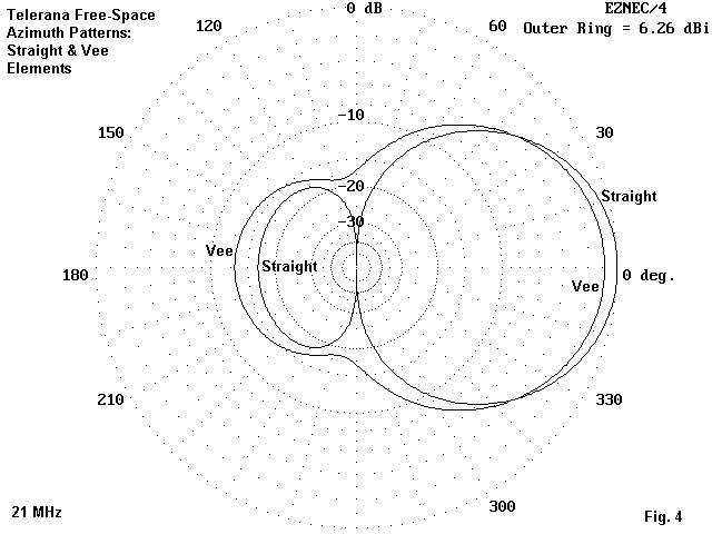
Fig. 4 shows the same two free-space azimuth patterns at 21 MHz. The same phenomena apply, as they do at 28 MHz, as shown in Fig. 5.
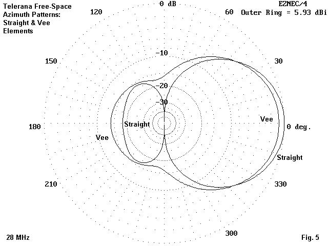
I have shown several comparative azimuth patterns to establish that the pattern shapes for each antenna are not isolated or frequency-specific phenomena. The once-prevalent notion that Vee-ing elements increased gain has proven to have no foundation in any modeling that I have done with arrays based on 1/2 wl elements. In all cases, Vee-ing elements reduces gain, front-to-back ratio, and front-to-side ratio. Anyone who desires to examine the basis for these reductions should begin first by comparing a 1/2 wl dipole with a Vee of the same element length. What happens to the pattern for a single element simply accumulates for arrays of similar elements.
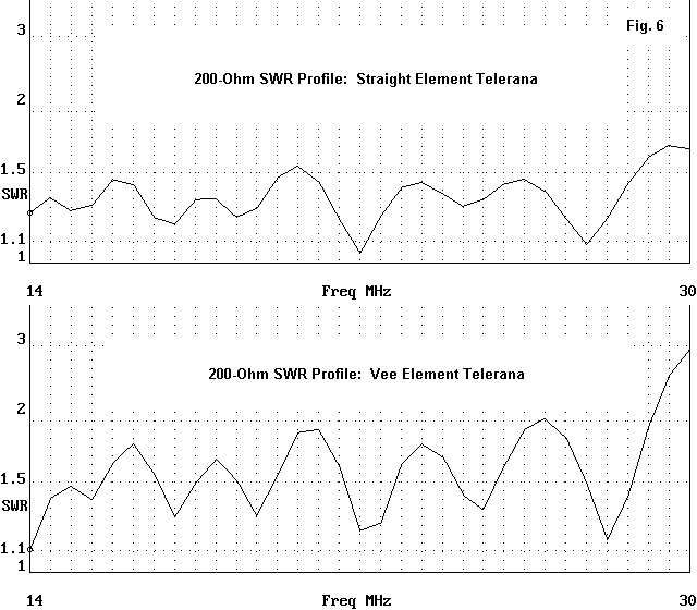
Although Vee-ing the elements in the Telerana yields an acceptable 200-Ohm SWR profile across the passband of the antenna, the equivalent profile for the straight-element design is somewhat superior, with smaller excursions in both the resistive and reactive components of the feedpoint impedance. Fig. 6 shows the two profiles for comparison. The Vee model would show an acceptable feedpoint impedance only up to about 29 MHz, but at the end of a 4:1 balun-plus-coaxial feedline, the SWR might appear to be somewhat lower.
Lest the Vee model be open to question, I performed a convergence test on it. To ensure that there were equal segments lengths on either side of the source/phaseline segment at the element centers, I increased the number of segments to 3. This required an increase by a factor of 3 for the number of segments on each wire making up the outer sections of the elements. For comparison, here are some values for the smaller and larger models of the Vee-d Telerana.
Freq.          F-S Gain       Front-Back     Feedpoint Impedance
MHz            dBi            dB             (R +/- jX Ohms)

14.0
Smaller        4.50            7.53          195.0 - j 19.5
Larger         4.48            7.53          190.6 - j 19.9

18.12
Smaller        5.21           11.16          213.6 - j 91.5
Larger         5.17           11.15          203.7 - j 92.2

21.0
Smaller        5.21           12.17          195.0 - j 19.5
Larger         5.36           12.14          190.6 - j 19.9

24.95
Smaller        5.18           12.75          256.7 + j 22.5
Larger         5.14           12.76          258.7 + j 12.3

28.0
Smaller        5.14           13.06          173.8 - j  3.5
Larger         5.06           13.04          172.9 - j  7.1
Nothing in the differences in the values returned by NEC-4 suggests that anything is amiss in the general accuracy of the analysis.
A similar set of considerations applies to the decision on whether to use wire or tubular elements. Wire is lighter than tubing. However, tubing may be obtained in much larger diameters than wire. The only question to which modeling can contribute an answer is whether larger diameter tubing offers any advantages in antenna performance over the same design in wire.
To answer this question, I changed diameter of the elements in the straight-element model from #14 AWG to 0.5". The increase factor is nearly 8. Since the elements in the model are of uniform diameter, the choice of 0.5" as the new diameter reflects the effective diameter of heavily stepped diameter elements that might begin with diameters of nearly 1" and descend to about 3/8" at the element tips. Therefore, as a modeling exercise, the comparison might well be representative of building practice.
For reference, here is the revised straight-element model description.
Telerana-Ant Bk 10-13: Straight: 0.5" elements     Frequency = 14  MHz.

Wire Loss: Copper -- Resistivity = 1.74E-08 ohm-m, Rel. Perm. = 1

              --------------- WIRES ---------------

Wire Conn.--- End 1 (x,y,z : ft)  Conn.--- End 2 (x,y,z : ft)  Dia(in) Segs

1          0.000,-20.330,  0.000         0.000, 20.330,  0.000 5.00E-01  39
2          4.060,-18.300,  0.000         4.060, 18.300,  0.000 5.00E-01  35
3          7.710,-16.460,  0.000         7.710, 16.460,  0.000 5.00E-01  31
4         11.020,-14.820,  0.000        11.020, 14.820,  0.000 5.00E-01  29
5         13.970,-13.310,  0.000        13.970, 13.310,  0.000 5.00E-01  25
6         16.630,-12.000,  0.000        16.630, 12.000,  0.000 5.00E-01  23
7         19.050,-10.790,  0.000        19.050, 10.790,  0.000 5.00E-01  21
8         21.140, -9.710,  0.000        21.140,  9.710,  0.000 5.00E-01  19
9         23.150, -8.720,  0.000        23.150,  8.720,  0.000 5.00E-01  17
10        24.890, -7.870,  0.000        24.890,  7.870,  0.000 5.00E-01  15
11        26.470, -7.080,  0.000        26.460,  7.080,  0.000 5.00E-01  13
12        27.890, -6.360,  0.000        27.890,  6.360,  0.000 5.00E-01  13
13        29.160, -5.740,  0.000        29.160,  5.740,  0.000 5.00E-01  11

              -------------- SOURCES --------------

Source    Wire      Wire #/Pct From End 1    Ampl.(V, A)  Phase(Deg.)  Type
          Seg.     Actual      (Specified)

1           6    13 / 50.00   ( 13 / 50.00)      1.000       0.000       V

No loads specified

                -------- TRANSMISSION LINES ---------

Line  Wire #/% From End 1   Wire #/% From End 1    Length     Z0   Vel Rev/
      Actual  (Specified)   Actual  (Specified)              Ohms Fact Norm

1    1/50.0  (  1/50.0)    2/50.0  (  2/50.0)  Actual dist  200.0  1.00  R
2    2/50.0  (  2/50.0)    3/50.0  (  3/50.0)  Actual dist  200.0  1.00  R
3    3/50.0  (  3/50.0)    4/50.0  (  4/50.0)  Actual dist  200.0  1.00  R
4    4/50.0  (  4/50.0)    5/50.0  (  5/50.0)  Actual dist  200.0  1.00  R
5    5/50.0  (  5/50.0)    6/50.0  (  6/50.0)  Actual dist  200.0  1.00  R
6    6/50.0  (  6/50.0)    7/50.0  (  7/50.0)  Actual dist  200.0  1.00  R
7    7/50.0  (  7/50.0)    8/50.0  (  8/50.0)  Actual dist  200.0  1.00  R
8    8/50.0  (  8/50.0)    9/50.0  (  9/50.0)  Actual dist  200.0  1.00  R
9    9/50.0  (  9/50.0)   10/50.0  ( 10/50.0)  Actual dist  200.0  1.00  R
10  10/50.0  ( 10/50.0)   11/50.0  ( 11/50.0)  Actual dist  200.0  1.00  R
11  11/50.0  ( 11/50.0)   12/50.0  ( 12/50.0)  Actual dist  200.0  1.00  R
12  12/50.0  ( 12/50.0)   13/50.0  ( 13/50.0)  Actual dist  200.0  1.00  R

Ground type is Free Space
The other change occasioned by the altered element diameter was the choice of the optimal inter-element phasing line characteristic impedance. Although higher gain levels are possible with lower phase line impedances, evidences of harmonic operation of longer wires shows up especially in the 15 meter band. These would have required compensating treatment, such as the addition of a stub. The result would have altered overall performance enough to cast doubt on the fairness of the comparison. Therefore, I selected a 200-Ohm line with no further "doctoring" of the design.
I also left the material as copper: The difference in performance values by using aluminum will be 0.01 dB of gain and 0.01 dB of front-to-back ratio. Once the diameter of an element reaches a certain level, changes of conductivity in the range between copper and aluminum no longer make a significant difference in the radiation efficiency of otherwise equivalent elements. In the upper HF region, that diameter is about a half inch.
However, diameter differences between #14 wire and 0.5" tubing can make a significant difference in performance. This difference shows up not only in LPDA designs, but as well in other arrays. One reason that multi-element quads fail to achieve their theoretically possible improvement over Yagis with an equal number of elements is not a function of basic design. Instead, it involves the habitual use of small-diameter wire in quad elements. Increasing the element diameters to a half-inch or more shows a much higher potential for quad designs, whatever the mechanical difficulties of implementing such designs.
Similar differences show up in LPDA designs, as the following table will attest.
Frequency           Free-Space Gain (dBi)         Front-to-Back Ratio (dB)
   MHz              #14            0.5"           #14            0.5"
14.0                5.71           6.39           11.63          15.59
14.175              5.71           6.37           11.69          15.63
14.35               5.72           6.36           11.79          15.81

18.12               6.08           6.59           15.85          21.01

21.0                6.26           6.90           16.70          17.90
21.225              6.24           6.92           16.70          17.72
21.45               6.21           6.99           16.92          16.49

24.95               6.13           6.66           18.16          21.31

28.0                5.93           6.45           18.23          20.79
28.5                5.86           6.39           17.77          20.30
29.0                5.81           6.36           17.31          19.65
29.5                5.79           6.35           16.87          18.89
30.0                5.80           6.38           16.48          18.09
At the 21.45 MHz marker, one can see evidence of the onset of harmonic operation with the peak gain that opposes the curve for the wire model. The lowering of the front-to-back ratio below expected norms is also a clue to this phenomenon. Reducing the phase line impedance to 100 or 150 Ohms allows the harmonic operation to become graphic. Indeed, even for the 200-Ohm phase-line model, I would recommend stub treatment to suppress this phenomenon or to move it well outside the ham bands. There is some literature that suggests the operation of LPDAs in harmonic mode for added gain. However, combined fundamental and harmonic operation of elements is generally to be avoided in LPDAs operating over an octave or more range. Smooth performance figures over the frequency bands or interest become more difficult to obtain where both fundamental and harmonic operation are combined.
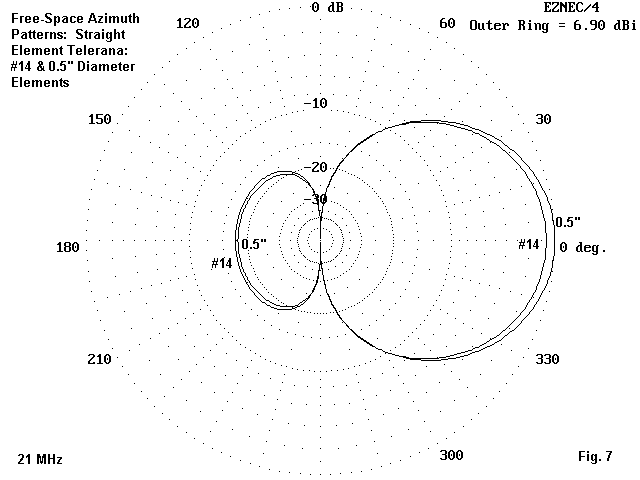
The average gain for the wire model is 5.99 dBi and the front-to-back ratio average to 15.94 dB. The 0.5" model shows 6.58 dBi and 19.06 dB as the comparable averages. Although the gain figure is only about 0.6 dB more, the 3 dB advantage in front-to-back ratio may well be worthy. Fig. 7 shows one representative comparison: the overlaid free-space azimuth patterns of the wire and tube models at 21 MHz.
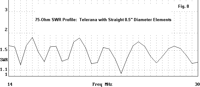
The lower phase-line characteristic impedance yields a lower design feedpoint impedance. Although it might well be refined further, 75 Ohms provides a reasonable reference for an SWR profile. As Fig. 8 shows, the 0.5" model has a well-behaved SWR curves relative to the reference.
Additional design refinements are certainly possible. We have already noted the utility of adding a stub to this model. The element might also be increased in size, working from the shortest element and increasing the diameter by the inverse of Tau. Likewise, circularization of Tau, especially at the lower end of the spectrum, would tend to equalize the gain and front-to-back ratio across the passband at the highest level obtained near mid-band.
I shall not try to implement such revisions in this exercise. The goal of this study has been to compare straight-wire LPDA design to designs using Vee-ed elements and to compare thin-wire and fat-wire elements within the same design. Having done that much, it is time to set the Telerana at rest.
Nothing in this analysis has tried to be critical of the Telerana design. It is a mechanical marvel of stressed fiberglass support of a complex wire assembly. This analysis has looked at some electrical properties of LPDAs without regard for the ease or difficulty of implementation. Only the Telerana electrical design has been brought to the modeling table. The mechanical aspect of the Telerana remains a classic in amateur antenna design.
In this space, we cannot develop a complete data base of wire equivalents to tubes. First of all, too many tube sizes are used to make this feasible. Second, the wire spacing will depend on the wire size used, and that multiplies the number of possibilities. However, we can make a small demonstration and show the modeling procedures one might use to develop a specific substitution.
Let's begin with the longest element of the Telerana in its 0.5" implementation. If we separate that element from the LPDA of which it is a part, we can find its resonant frequency. The 487.92" (40.66') element resonates at 11.63 MHz with a source impedance of 72.0 - j 0.1 Ohms. I generally set a reactance of +/-j1 Ohm as the criterion of resonance for most investigations--a figure somewhat more precise than we would need for an operational situation.
Now let's take 2 #14 AWG wires and make them parallel. Now we must figure out how to feed the wires without creating a folded dipole. Fig. 9 shows the general technique.
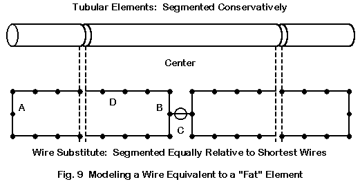
We create a short single center section of 1 segment (C). Then, we create short wires from the center section to each long wire of the pairs (B). This will make 2 wires, which we recreates with a single 2-segment wire at the far ends of the assembly (A). Each horizontal wire (D) is appropriately segmented.
The ideal situation would require that all wire segments be of approximately equal length. Hence, the lengths, of segments in A, B, C, and D would be the same. Equalizing the segment (wire) lengths of B and C is especially important. The far-end wires (A) can be of 1 or 2 segments: the difference makes little difference to the result. The segments of the parallel wires (D) should be no more than about 1.5 to 2.0 times the length of B or C. Working outside these dimensions generally yields poor results from the wire model.
A parallel-wire (#14 AWG) model of the 0.5" element yielded resonance at 11.60 MHz when the wires were 2" apart. With 120 segments each side of center along wire D, the feedpoint impedance was 72.81 + j0.3 Ohms, which was satisfactorily close to the value for the 0.5" tube. One might have nudged the spacing more precisely to place the resonance at 11.63 MHz, but the convenient 2" spacing number would have been lost.
So far, we have created a single element out of wire, one that has the same length as the original tube. One reason we wanted to preserve the length is to also preserve the current distribution along the length of the element. This function is just as important to LPDA operation as the phase line, since mutual coupling works together with phased element feed to yield the LPDA performance.
Will these substitution elements produce the same performance as the tubular original elements in an LPDA design? To create a little demonstration, let's look at a simpler design than the one with which we have been working. The reasons for this will become self-evident in a bit. The design we shall use is one that appears in The ARRL Antenna Book as a little exercise. It is not an especially good LPDA, but its merit is that it is small and designed for 17-10 meters. The model description of the test version follows.
17-10m Log Per - ARRL Ant Book              Frequency = 18.12  MHz.

Wire Loss: Aluminum -- Resistivity = 4E-08 ohm-m, Rel. Perm. = 1

              --------------- WIRES ---------------

Wire Conn.--- End 1 (x,y,z : in)  Conn.--- End 2 (x,y,z : in)  Dia(in) Segs

1          0.000,-163.46,  0.000         0.000,163.460,  0.000 5.00E-01  37
2         39.230,-130.76,  0.000        39.230,130.760,  0.000 5.00E-01  29
3         70.620,-104.62,  0.000        70.620,104.620,  0.000 5.00E-01  23
4         95.720,-83.690,  0.000        95.720, 83.690,  0.000 5.00E-01  19
5        115.810,-66.950,  0.000       115.810, 66.950,  0.000 5.00E-01  15

              -------------- SOURCES --------------

Source    Wire      Wire #/Pct From End 1    Ampl.(V, A)  Phase(Deg.)  Type
          Seg.     Actual      (Specified)

1           8     5 / 50.00   (  5 / 50.00)      1.000       0.000       I

No loads specified

                -------- TRANSMISSION LINES ---------

Line  Wire #/% From End 1   Wire #/% From End 1    Length     Z0   Vel Rev/
      Actual  (Specified)   Actual  (Specified)              Ohms Fact Norm

1    1/50.0  (  1/50.0)    2/50.0  (  2/50.0)  Actual dist  490.1  1.00  R
2    2/50.0  (  2/50.0)    3/50.0  (  3/50.0)  Actual dist  490.1  1.00  R
3    3/50.0  (  3/50.0)    4/50.0  (  4/50.0)  Actual dist  490.1  1.00  R
4    4/50.0  (  4/50.0)    5/50.0  (  5/50.0)  Actual dist  490.1  1.00  R
5    1/50.0  (  1/50.0)  Short ckt (Short ck)    6.000 in   490.1  1.00

Ground type is Free Space
This model also appears as an example in the EZNEC software.
Now let's present the substitute wire-element model.
17-10m Log Per Ant Bk Wire Sub              Frequency = 18.12  MHz.

Wire Loss: Copper -- Resistivity = 1.74E-08 ohm-m, Rel. Perm. = 1

              --------------- WIRES ---------------

Wire Conn.--- End 1 (x,y,z : in)  Conn.--- End 2 (x,y,z : in)  Dia(in) Segs

1   W3E1 -163.46, -1.000,  0.000  W2E1  -1.000, -1.000,  0.000    # 14   60
2   W1E2  -1.000, -1.000,  0.000  W5E2  -1.000,  0.000,  0.000    # 14    1
3   W1E1 -163.46, -1.000,  0.000  W4E1 -163.46,  1.000,  0.000    # 14    2
4   W3E2 -163.46,  1.000,  0.000  W5E1  -1.000,  1.000,  0.000    # 14   60
5   W4E2  -1.000,  1.000,  0.000  W6E1  -1.000,  0.000,  0.000    # 14    1
6   W2E2  -1.000,  0.000,  0.000  W7E1   1.000,  0.000,  0.000    # 14    1
7  W10E1   1.000,  0.000,  0.000  W8E1   1.000,  1.000,  0.000    # 14    1
8   W7E2   1.000,  1.000,  0.000  W9E1 163.460,  1.000,  0.000    # 14   60
9   W8E2 163.460,  1.000,  0.000 W11E2 163.460, -1.000,  0.000    # 14    2
10  W6E2   1.000,  0.000,  0.000 W11E1   1.000, -1.000,  0.000    # 14    1
11 W10E2   1.000, -1.000,  0.000  W9E2 163.460, -1.000,  0.000    # 14   60
12 W14E1 -130.76, 38.230,  0.000 W13E1  -1.000, 38.230,  0.000    # 14   50
13 W12E2  -1.000, 38.230,  0.000 W16E2  -1.000, 39.230,  0.000    # 14    1
14 W12E1 -130.76, 38.230,  0.000 W15E1 -130.76, 40.230,  0.000    # 14    2
15 W14E2 -130.76, 40.230,  0.000 W16E1  -1.000, 40.230,  0.000    # 14   50
16 W15E2  -1.000, 40.230,  0.000 W17E1  -1.000, 39.230,  0.000    # 14    1
17 W13E2  -1.000, 39.230,  0.000 W18E1   1.000, 39.230,  0.000    # 14    1
18 W21E1   1.000, 39.230,  0.000 W19E1   1.000, 40.230,  0.000    # 14    1
19 W18E2   1.000, 40.230,  0.000 W20E1 130.760, 40.230,  0.000    # 14   50
20 W19E2 130.760, 40.230,  0.000 W22E2 130.760, 38.230,  0.000    # 14    2
21 W17E2   1.000, 39.230,  0.000 W22E1   1.000, 38.230,  0.000    # 14    1
22 W21E2   1.000, 38.230,  0.000 W20E2 130.760, 38.230,  0.000    # 14   50
23 W25E1 -104.62, 69.620,  0.000 W24E1  -1.000, 69.620,  0.000    # 14   40
24 W23E2  -1.000, 69.620,  0.000 W27E2  -1.000, 70.620,  0.000    # 14    1
25 W23E1 -104.62, 69.620,  0.000 W26E1 -104.62, 71.620,  0.000    # 14    2
26 W25E2 -104.62, 71.620,  0.000 W27E1  -1.000, 71.620,  0.000    # 14   40
27 W26E2  -1.000, 71.620,  0.000 W28E1  -1.000, 70.620,  0.000    # 14    1
28 W24E2  -1.000, 70.620,  0.000 W29E1   1.000, 70.620,  0.000    # 14    1
29 W32E1   1.000, 70.620,  0.000 W30E1   1.000, 71.620,  0.000    # 14    1
30 W29E2   1.000, 71.620,  0.000 W31E1 104.620, 71.620,  0.000    # 14   40
31 W30E2 104.620, 71.620,  0.000 W33E2 104.620, 69.620,  0.000    # 14    2
32 W28E2   1.000, 70.620,  0.000 W33E1   1.000, 69.620,  0.000    # 14    1
33 W32E2   1.000, 69.620,  0.000 W31E2 104.620, 69.620,  0.000    # 14   40
34 W36E1 -83.690, 94.720,  0.000 W35E1  -1.000, 94.720,  0.000    # 14   30
35 W34E2  -1.000, 94.720,  0.000 W38E2  -1.000, 95.720,  0.000    # 14    1
36 W34E1 -83.690, 94.720,  0.000 W37E1 -83.690, 96.720,  0.000    # 14    2
37 W36E2 -83.690, 96.720,  0.000 W38E1  -1.000, 96.720,  0.000    # 14   30
38 W37E2  -1.000, 96.720,  0.000 W39E1  -1.000, 95.720,  0.000    # 14    1
39 W35E2  -1.000, 95.720,  0.000 W40E1   1.000, 95.720,  0.000    # 14    1
40 W43E1   1.000, 95.720,  0.000 W41E1   1.000, 96.720,  0.000    # 14    1
41 W40E2   1.000, 96.720,  0.000 W42E1  83.690, 96.720,  0.000    # 14   30
42 W41E2  83.690, 96.720,  0.000 W44E2  83.690, 94.720,  0.000    # 14    2
43 W39E2   1.000, 95.720,  0.000 W44E1   1.000, 94.720,  0.000    # 14    1
44 W43E2   1.000, 94.720,  0.000 W42E2  83.690, 94.720,  0.000    # 14   30
45 W47E1 -66.950,114.810,  0.000 W46E1  -1.000,114.810,  0.000    # 14   25
46 W45E2  -1.000,114.810,  0.000 W49E2  -1.000,115.810,  0.000    # 14    1
47 W45E1 -66.950,114.810,  0.000 W48E1 -66.950,116.810,  0.000    # 14    2
48 W47E2 -66.950,116.810,  0.000 W49E1  -1.000,116.810,  0.000    # 14   25
49 W48E2  -1.000,116.810,  0.000 W50E1  -1.000,115.810,  0.000    # 14    1
50 W46E2  -1.000,115.810,  0.000 W51E1   1.000,115.810,  0.000    # 14    1
51 W54E1   1.000,115.810,  0.000 W52E1   1.000,116.810,  0.000    # 14    1
52 W51E2   1.000,116.810,  0.000 W53E1  66.950,116.810,  0.000    # 14   25
53 W52E2  66.950,116.810,  0.000 W55E2  66.950,114.810,  0.000    # 14    2
54 W50E2   1.000,115.810,  0.000 W55E1   1.000,114.810,  0.000    # 14    1
55 W54E2   1.000,114.810,  0.000 W53E2  66.950,114.810,  0.000    # 14   25

              -------------- SOURCES --------------

Source    Wire      Wire #/Pct From End 1    Ampl.(V, A)  Phase(Deg.)  Type
          Seg.     Actual      (Specified)

1           1    50 / 50.00   ( 50 / 50.00)      1.000       0.000       V

No loads specified

                -------- TRANSMISSION LINES ---------

Line  Wire #/% From End 1   Wire #/% From End 1    Length     Z0   Vel Rev/
      Actual  (Specified)   Actual  (Specified)              Ohms Fact Norm

1    6/50.0  (  6/50.0)   17/50.0  ( 17/50.0)  Actual dist  490.1  1.00  R
2   17/50.0  ( 17/50.0)   28/50.0  ( 28/50.0)  Actual dist  490.1  1.00  R
3   28/50.0  ( 28/50.0)   39/50.0  ( 39/50.0)  Actual dist  490.1  1.00  R
4   39/50.0  ( 39/50.0)   50/50.0  ( 50/50.0)  Actual dist  490.1  1.00  R
5    6/50.0  (  6/50.0)  Short ckt (Short ck)    6.000 in   490.1  1.00

Ground type is Free Space
This 55-wire, 865-segment model is sizable and slow running. However, it is considerably shorter and faster than had we presented the wire substitute for the Telerana with its 13 elements replaced by 143 wires and well over double the total number of segments as the small model. The smaller model is also a good test of the substitution, since it does not have especially good performance. If the substitute were a poor one, we could expect results that significantly diverge from the original.
The following table shows how the original and the substitute fared in modeling tests at sample frequencies.
Frequency           Free-Space Gain     Front-Back Ratio    Feed Impedance
  MHz                    dBi                 dB             R +/- jX Ohms
18.12
Original                 4.44                6.42            60.2 + j 95.8
Substitute               4.35                6.29            72.3 + j112.5

21.0
Original                 4.47                6.15           142.9 - j 87.0
Substitute               4.43                6.10           127.6 - j 70.5

24.95
Original                 5.09                7.94           382.8 - j 82.3
Substitute               5.07                8.02           330.0 - j141.6

28.0
Original                 5.36                9.81           105.3 - j 54.8
Substitute               5.32                9.81           102.7 - j 36.9
The maximum gain differential is 0.09 dB and the maximum front-to-back differential is 0.13 dB. The very small gain degradation stems in part from the smaller area available on the two wire surfaces compared to the surface of the larger tube. The original tube from which we derived the substitute 2-wire spacing had a dipole gain of 2.13 dBi, while the substitute had a gain of 2.07 dBi in free space.
Although the impedance differences are greater, they are in part attributable to the slight difference we selected for resonant frequencies for the elements in order to preserve round numbers for with wire spacing. However, the impedance differences are not great enough to disturb the general trends of an SWR profile.
The demonstration shows that it is possible to develop 2-wire equivalents of larger elements. The technique used to develop the #14 wire substitute for 0.5" elements can be replicated to make substitutes out of almost any wire size for any size original element. The demonstration also shows that the performance of the 2-wire substitute can be effectively modeled with due attention to the constraints of NEC segmentation--and if one is willing to work with larger models that require considerable run time.
Whether the 2-wire substitute element would be satisfactory in an actual LPDA antenna involves mechanical considerations beyond the scope of this modeling exercise. Nonetheless, it is an option that the LPDA designer- builder should not overlook in the quest for an adequate LPDA.
Needless to say, the 5-element demonstration model would be hardly worth the effort of building. There are far better designs with which to work.
Updated 10-22-99. © L. B. Cebik, W4RNL. Data may be used for
personal purposes, but may not be reproduced for publication in print or
any other medium without permission of the author.