 Preliminary Notes on Trap Placement
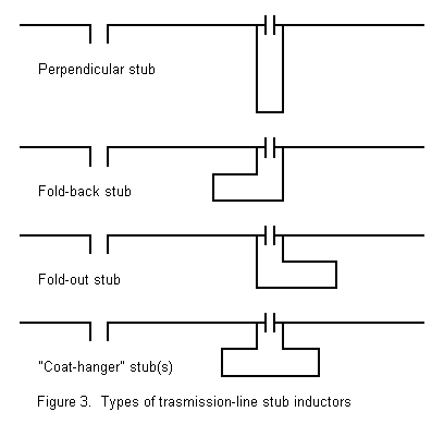
To achieve even higher inductor Qs, some builders have employed so-called linear inductors. A linear inductor is nothing more or less than a shorted transmission line stub. The stub may use either an existent commercial parallel transmission line or be constructed especially for a particular antenna design. The stub may be run perpendicular to the antenna element. For mechanical reasons, the stub is often folded back or outward along the antenna element. Samples of such lines are shown in Figure 3.

For small values of inductive reactance, the required length will adhere closely to standard stub calculations. If the folded stub lines are equidistant from the main element, the stub length will by slightly shorter than if the lines are run in a plane with the element. When the lines are placed in a plane, the induced currents from the element field are unequal in the two lines and therefore do not fully cancel.
Of special note is the so-called "coat-hanger" inductor. To calculate this line requires that we treat it as two inductive reactances in series, one for each half of the inductor. Otherwise, its properties are essentially similar to the folded inductors. As we shall see, folding the inductor toward the feedpoint or toward the element end makes no significant difference in performance.

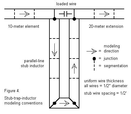
Investigating stub inductors via NEC-4 models calls for attention to program limitations. The models used in this preliminary investigation adhere to the general outline shown in Figure 4. The higher frequency element is terminated one segment shy of its true end (remembering that the trap is part of the element). A single segment, 0.5' long is added. This segment is loaded with the capacitive reactance of the trap capacitor. Since the alternative inductor trap designs adhered to the values of the conventional traps, the target capacitance is 26.92 pF, which yields reactances of 207.4 ohms at 28.5 MHz and 417.1 ohms at 14.175 MHz. The capacitor is not assigned any resistive losses. To the end of the loaded segment, the 20 meter extension is added to complete the linear portion of the assembly.
The stub is a physically modeled wire assembly. Each parallel line connects to the junction at either end of the loaded 1-segment wire, with a shorting bar (wire) at the far end of the parallel wires. Two precautions must be met. The direction of the wire assembly is significant, since the current direction in the two wires is roughly opposite. Exact opposition is not the case with these assemblies, since the current magnitude and phase are not identical at the two terminals. As well, the segmentation should be as close to identical in the two wires as possible to permit each segment to align with its counterpart in the other parallel wire.
NEC-4 presents some accuracy concerns for wires of different diameters that are parallel or which meet at angles. To minimize these errors, the shorted transmission line stub was constructed of the same materials as the main element: 0.5" diameter aluminum spaced 0.5' apart. Folded models space the inner wire 0.5' from the main element, with the outer wire 1.0' from the main element. These constraints permit NEC-4 to operate well within its design limitations. Independent calculations of stubs of this design yielded a required length of 2.83' for the 28 MHz inductive reactance of 211 ohms. (A 450-ohm parallel line with a velocity factor of 0.95 would require 2.33' of shorted stub.)
Relative to real-world construction practices, the stubs are too fat and too widely spaced. The foldback models will show excess gain that is a function of the fat inductor wires, as well as a small but significant vertically polarized radiation component. Actual antenna elements using thinner wires more closely spaced to the main element will likely fail to realize the excess gain and lose much of the vertically polarized radiation. Relative to standard stub calculations, which presume that the shorting bar has no significant dimension, the widely spaced stubs will be slightly shorter than calculated lengths, with some of the length occupied by the shorting bar's approach to center-point.
Despite these constraints--which limit the direct application of the models to a test antenna--modeling alternative trap inductors provides some data that is extremely useful, even if only in marking trends.
{The copper wire antenna of #14 wire with dimensions in inches makes it convenient to add segments and to produce somewhat more realistic transmission line stubs. The average segment in wire antenna models is between 3" and 4" and therefore, a segment of 4" was selected as the loaded segment. This set the stub construction of 4" spaced wires of #14 copper. The precalculated stub length was 23.472" (1.956'). In all other respects, the wire antenna models follow the rules set forth for the aluminum models.}
The performance of the antenna was as follows (with the Q=200 model shown for comparison):
Trap Coil Q=200
Frequency      Gain (dBi)          Feed Z (R+/-jX)
28.5 MHz       2.03                83.63 - j0.33
14.175 MHz     1.98                63.56 - j0.72

Perpendicular Stub 2.313'
Frequency      Gain (dBi)          Feed Z (R+/-jX)
28.5 MHz       1.53                63.29 - j0.76
14.175 MHz     2.02                52.99 + j0.91
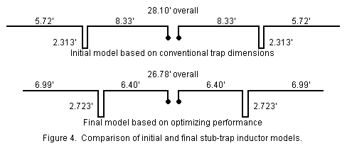
Two data discrepancies should call themselves to immediate attention. First, the 10-meter gain has suffered a very serious drop (0.5 dB). Second the 10-meter feedpoint impedance is 20 ohms less than the Q=200 conventional trap model. In addition, the stub length is very seriously shorter than predicted.
The error in this model might be difficult to assess in practice, since this is an antenna that can be made to operate and to show resonance on both bands. What the error is becomes immediately apparent when we remember that the trap assembly, treated as a load, is a part of the 10- meter antenna. Although the antenna shows a resonance at 28.5 MHz, it is not configured for maximum radiation effectiveness.

A correct model requires that the 10-meter section of the antenna be shortened. A useful target for this shortening is maximum 10-meter gain. Figure 5 contrasts the dimensions of the initial and the final model (which might be tweaked even further). The stub is now across a capacitively loaded wire running from 5.9 to 6.4' from the feedpoint. To the trap ends are added 6.99' 20-meter extensions for an overall 26.78' length. The required stub increased to 2.723' long, a figure much closer to the calculated 2.83' once the shorting bar is considered. Evidence of being close to optimum for this antenna design is the fact that the current phases of the loaded element and the stub shorting bar are almost exactly 180 degrees apart, with allowance for the slightly different current magnitudes occasioned by aluminum losses in the modeled stub lines. In this configuration, the performance figures are these:
Perpendicular Stub 2.723'
Frequency      Gain (dBi)          Feed Z (R+/-jX)
28.5 MHz       2.00                73.82 - j0.96
14.175 MHz     1.99                45.09 + j0.44
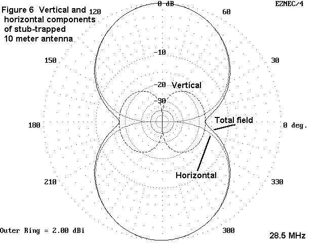
Evidence that the stub lines play a role in determining the overall length of the 10-meter segment comes not only from the gain and feedpoint figures, but as well from the vertically polarized radiation component in the antenna's free space azimuth pattern. The vertically polarized component is only about 18 dB down from the main antenna lobe. Figure 6 is a free space 10-meter pattern for the antenna with both vertical and horizontal components shown.

{Copper wire models corresponding to the aluminum models were constructed. The overall length of the wire antenna was 348.8" with 145.6" between the stub sections and 153.6" including the stubs. The distance including the traps is identical to that of the aluminum model. Given the thinner copper wire and the trend toward higher gain figures, we would expect to see a gain value at or just slightly higher than the figure for the aluminum model. This expectation is predicated on the view that the effective Q of the stubs is much higher than the the Qs of either antenna model, as outlined in Part 1 of this study. If the relationship of antenna Q to trap Q does not obtain, then 10-meter peformance should merely track conventional trap performance, and the gain of the antenna on 10 meters would likely be significantly less than 2.0 dBi.
{At 20 meters. the 95" (7.92') extensions confirm the lower remnant reactance value of stubs relative coils. Since the chief effect of the stubs at 20 meters is inductive loading, we would expect the 20 meter gain to be slightly lower than that of the aluminum model, given the greater losses in the thinner wire.
{The performance figures for the copper wire antenna are as follows:
Perpendicular Stub 21.59"
Frequency      Gain (dBi)          Feed Z (R+/-jX)
28.5 MHz       2.08                90.83 + j0.41
14.175 MHz     1.86                52.81 - j0.05
{The feedpoint impedance of the 10 meter model reflects very well the feedpoint impedance of the conventional trap model, suggesting that the stub placement is fairly well optimized. (The aluminum model might stand a bit more tweaking in this respect.) The gain is above that of the aluminum model by an insignificant amount, given the methods used here. However, the similarity of the values for comparably placed stubs is significant, as is the 0.25 dB gain improvement over the conventional trap with a Q of 200.
{The suggested rule of thumb for antenna segments at the trap frequency is this: For maximum gain, the trap Q must exceed the antenna element Q by some significant amount. Once that value is reached, resorting to higher Q traps leads to little gain improvement (although there may be mechanical reasons for selecting a higher Q design). We have provided no clear definition of antenna Q in this context. Such a definition and the development of gain expectation curves is a detailed investigation beyond the scope of available time.
{At 20 meters, the gain of the antenna is lower than with a conventional trap, largely due to the further shortening of the overall antenna length. The stub trap antenna is about 1' shorter than the conventional trap model, with a consequential further erosion of gain as it is related to antenna length. This reduction overrides the advantages of longer 20-meter extensions and trap Q at 20 meters. Trap Q does play a role, since lower Q traps at this length would further reduce 20 meter gain. The stub trap antenna at 20 has a gain intermediate between the gain of the longer conventional trap antenna with traps of Q=75 and Q=200.}
There are additional factors at work in the increased gain shown by the placement of stubs inward from their anticipated positions. The resonant frequency of a physically modeled stub and a load capacitance (or capacitive reactance) is difficicult to determine in the course of modeling. Hence, the search for the maximum gain point does not ensure that the stub is indeed resonant at the same frequency as a precalculated load consisting of R-L-C components. As the resonant frequency of a trap is lowered further below the operating frequency, two phenomena occur: 1. The gain of the antenna increases and 2. the length of the trapped section decreases. Consequently, the use of a maximum gain criterion as the marker of correct trap placement most likely indicates that the trap is resonant on a frequency well below the operating frequency. That the 20 meter gain decreased slightly is a further indication of a lowered trap resonance frequency.
Since one major goal of a dipole is gain (with the other being a usable freedpoint impedance), the seemingly radical shortening of the element poses no significant problems. However, in multi-element antennas, geometric relationships of the elements also play a role in overall antenna performance, trap placement and consequenctial gain may be subject to compromise to achieve the best possible physical relationship among the elements for the desire performance.
Current levels in the parallel circuit made up by the stub and the capacitive loading wire are interesting. NEC-4 calculates only the losses of the capacitance load, not of the entire trap. However, physically modeling the trap assembly provides data on the current in the assembly. Current magnitude just prior to the trap is .52 (relative to 1.0) and just after the stub is .09. Within the trap, current varies from 1.15 to 1.57, indicating considerable circulating current within the assembly. (In the initial model, with its higher losses at 10 meters, the current peaked at 2.29 with much lower currents on either side of the trap.)
{We may note in passing that current levels in the wire antenna models corresponded quite reasonably with those of the aluminum model, again suggesting that the very high trap Q relative to the Q of either antenna model is the dominant factor in circulating current magnitude.}
For optimized 10-meter performance, the alternative trap assembly using a shorted stub inductor must be considered a part of the 10-meter segment of the antenna, and the linear portion of the assembly shortened accordingly. For 20-meters, the length of the extensions is a function of the net trap reactance at 14.175 MHz. Since a stub's reactance is a function of the tangent of its length, the remnant reactance of the stub is only about 70 ohms at 20 meters (in contrast to the 107 ohms remnant from the conventional trap coil). Hence, we should expect longer extensions for 20 meters with the stub design--and we get them: 6.99' in contrast to the 6.33' extensions for the conventional trap model.
The major difference among models was the required length for the extensions to bring the antenna to resonance on 20 meters. The fold-back model required extensions of 7.37' for a total antenna length of 27.54' overall. Extensions for the fold-out model were 7.47' for a 27.74' overall length.
Performance figures for the two models are these:
Fold-Back model:
Frequency      Gain (dBi)          Feed Z (R+/-jX)
28.5 MHz       2.34                79.23 + j0.79
14.175 MHz     1.94                47.37 - j0.36

Fold-Out Model
Frequency      Gain (dBi)          Feed Z (R+/-jX)
28.5 MHz       2.30                83.76 - j0.20
14.175 MHz     1.98                50.72 - j0.24
There is little to choose between the two models, given the limitations of the modeling technique which precludes assigning precision to the numbers. Performance is comparable to 0.04 dB and about 4 ohms for each antenna version. And, further tweaking of the designs is likely possible using either models or test antennas. It is quite unlikely that the excess 10- meter gain would be realized using smaller more closely spaced wires for the trap inductors.
10-meter circulating currents in the trap assemblies are quite comparable to those in the perpendicular trap version, reaching peaks of about 1.62 (relative to one). Interestingly, peak currents in the 20-meter wire extensions with an operating frequency of 28.5 MHz are almost twice as high in the fold-back model (where stub wires are parallel to the 10-meter element segments) than they are in the fold-out model (where stub wires are parallel to the extensions).
The use of folded stubs as trap elements provides some mechanical advantage in the construction of trap antennas. Their performance is at least as good as the use of conventional coils, if appropriate adjustments are made to the length of the 10-meter portion of the antenna to achieve maximum gain. If those adjustments are not made and the trap treated, as in the past, as an appendage to (rather than a part of) the 10-meter antenna, stub inductors are likely to give very disappointing 10-meter service.
There is an alternative trap procedure, suggested to me by ZL1ANJ and attributed to EA7BA, of using concentric but insulated antenna tubing as the entire trap. Presumably, the concentric length from the point at which the tubes are shorted (at an inward point) to some unspecified point along the way constitutes a coaxial stub. The remaining length of concentric tubing (until the inner tube emerges) provides the capacitance across the stub that is necessary for resonance. Although mechanically promising, this technique cannot be directly addressed by reasonably simple models. Hence, comparative performance remains unknown and will require field models for determination.
This study has been of a preliminary nature. Much work to tweak the
designs can be done. Too, much needs to be done to check the applicability
of the fat wide stub designs against stubs of more normal dimensions.
However, the investigation has fairly well established the need to treat
traps as parts of the antenna segment which they limit and to suggest
directions for the builder to take in constructing the most effective trap
antennas possible.
Updated 7-11-97. © L. B. Cebik, W4RNL. Data may be used for
personal purposes, but may not be reproduced for publication in print or
any other medium without permission of the author.