 A Trap Small Quad Beam for 12 and 17 Meters

Answer: yes, although it might be a somewhat finicky construction job, especially on 17 meters, where the shortening makes wire lengths somewhat more critical. However, the idea might be worth pursuing, since these are bands where many folks are looking for something better than a dipole, but not as expensive or as large as a full-size commercial beam.
Take two of the diamonds of #14 copper wire in Figure 1 and set them 8.15' feet apart. Make the driven element (forward) diamond just about 10' per side (actually, 39' 11 inches in circumference). The rear diamond should be just about 10.4' per side (circumference = 41' 7.5"). The resulting diamond quad is 14' 9" tall and the same size wide, which is fairly compact for a 12 and 17 meter antenna.
The capacity hats are the wires starting at the side points of the diamond. They begin with a wire 9" long, from which 2 wires extend parallel to the main loop wires. Each is just about 2' 5" long for each loop.
The traps are parallel inductor-capacitor combinations with a target reactance per component of 250 ohms, giving 1.6 microH and 25.5 pF. The design used a target Q of 200. Variations in Q or trap components will affect the required lengths for the hat wires parallel the loop wires for 17-meter resonance.
The resulting antenna produces feedpoint impedances in two ranges. For 17 meters, the impedance is just above 100 ohms, while on 12 the impedance is closer to 160 ohms. For a 50-ohm match, one bands wants a 2:1 transformation, while the other band prefers a 3:1 transformation.
A series section of 75-ohm coax with a velocity factor of 0.66 can be between 7' and 7.5' long and effect the transformations close enough to provide under 2:1 SWR across both bands. (Note, this is a simple series section chosen for its impedance transforming characteristics. It is not the usual 1/4 wl section.)
The predicted performance of the antenna is given in the following table derived from NEC-4 models:
Freq.    Gain  F-B     Natural     With 7'   SWR     With 7.5'   SWR
MHz      dBi   dB      Feed Z      RG-59     50      RG-59       50

18.068   5.67  12.71    96 - j11   42 + j 8  1.27    44 + j12    1.34
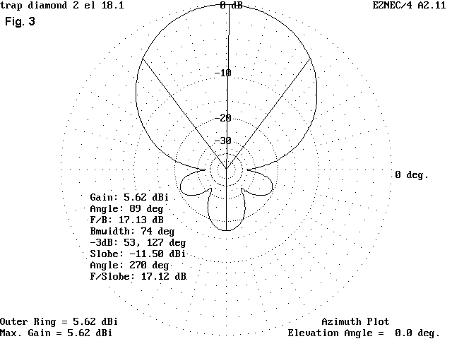
18.1     5.62  17.15   114 + j 4   47 - j 1  1.07    47 + j 3    1.08
18.168   5.35  29.41   149 + j22   44 - j16  1.43    43 - j12    1.34

24.89    6.87  18.37   160 - j 2   34 + j 7  1.54    35 + j14    1.63
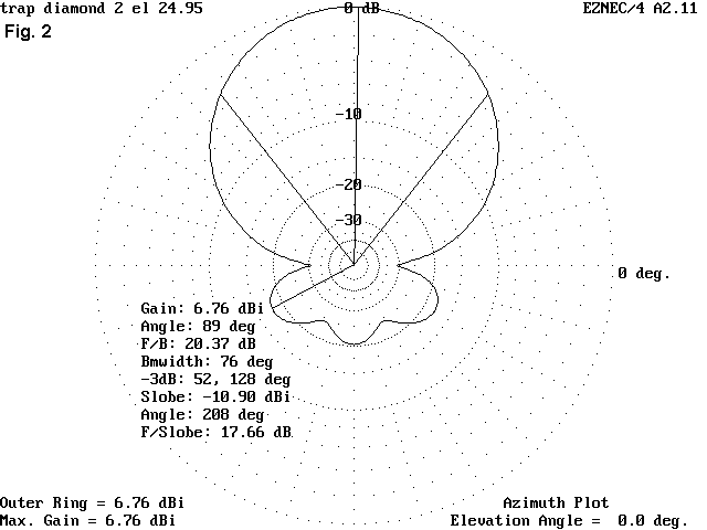
24.95    6.76  20.37   168 + j 3   32 + j 6  1.60    33 + j14    1.69
24.99    6.68  21.18   172 + j 6   31 + j 6  1.64    32 + j14    1.73
The next two figures illustrate the free space azimuth patterns for the mid-12 and mid-17 meter band points. The gain in 12 is quite decent, as is the front-to-back ratio. On 17, gain is down, although the front-to-back ratio holds up--a feature of shrunken 2-element antennas.


Both patterns are quite serviceable, although not exceptional. Since the antenna can likely be built on a stressed light PVC frame, in a manner similar to the construction I used for the 10-meter shrunken quad, experimenting with this design should not be a budget buster. If it does not work out to satisfaction, the PVC can be converted into tomato stakes next spring, and the wire used for other antennas.
Nothing in these design notes is certified by construction. But the design
techniques may have an adaptable idea or two for some other project. Or,
with some luck and patience, you might just end up with a usable small quad
for 12 and 17 meters.
Updated 9-29-97. © L. B. Cebik, W4RNL. Data may be used for personal purposes, but may not be reproduced for publication in print or any other medium without permission of the author.