I have received a number of inquiries over the last year or so concerning the best way to get omni-directional radiation from a horizontally polarized antenna on the HF bands. We have often tried to use the inverted Vee, but that antenna only turns the dipoles peanut-shaped pattern into an oval. The radiation off the ends of the wire is usually down by 8 to 12 dB--depending on the slope of the Vee legs--relative to the maximum gain broadside to the wire.
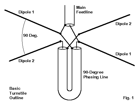
If you are truly serious about having an omni-directional horizontally polarized pattern, try the turnstile antenna. The turnstile was often used on VHF, especially in the days before repeaters, that is, when horizontal polarization was still standard. The antenna has dropped out of sight, but may have a new home on the HF bands for those who must use a fixed antenna but who also wish to have roughly equal radiation in all directions. The basic outlines are shown in Fig. 1.

The turnstile consists of two resonant dipoles at right angles to each other and crossing in the center. The two antennas do not touch. The main feedline (the usual 50-Ohm coax, with a 1:1 balun) goes to one dipole's feedpoint connections. A 90-degree phasing line of 72-Ohm coax goes from the main feedline connections to the other dipole feedpoint connections. The 90-degree phasing of the two dipoles is crucial in obtaining an omni-directional pattern.
The phasing line length will depend on the velocity factor of the line you use. 72-Ohm coax comes with either solid or foam insulation. The solid insulation usually gives the line a 0.66 velocity factor, while foam lines have a velocity factor of about 0.78.
Use the velocity factor as a multiplier on the basic 1/4 wavelength calculated from the frequency and wavelength of use in order to determine the physical length of the line. Let's use 10-meters as an example. 1/4 wavelength is about 8.63' at 28.5 MHz. A 0.66 VF line will be about 5.69' long, while a 0.78 VF line will be about 6.73' long. As with any antenna, be sure to weatherproof all connections to prevent rain from entering the coax line. Technically, coax is not necessary, but 72-Ohm parallel line is almost impossible to obtain in the U.S. Although the example is for 10 meters, the turnstile concept is relevant to any frequency whatsoever, from LF to UHF.
To build a turnstile, first build a single dipole and trim it to resonance. Then construct the second dipole to exactly the same dimensions. The construction details will depend on the band and materials. Add the phasing line, calculated for the band in use. Finally add the main feedline.
Let the phasing line hang down from the dipole junction. You can tape the "down" and "up" halves of the line together to control erratic swaying in the wind. However, it is best to space the line a bit from any metal mast you might use to support the antenna center.
Now the big question: what do we get for our efforts? The turnstile azimuth pattern for nearly any antenna height appears in Fig. 2.

The patterns is nearly circular. The maximum flattening along the sides is 2 dB or under for most common heights. The following table will give you some idea of the gain of the lowest lobe and the degree of "flattening" of the circle for various heights above ground in terms of wavelengths.
Height    Max. Gain      TO Angle       Flattening     Feedpoint Z
 wl          dBi          degrees          dB            Ohms
0.25      3.9            45 (arbitrary)   0             35.7
0.50      5.2            28               2.5           37.0
0.75      4.5*           18               1.5           36.0
1.00      4.7*           14               2.0           36.0
1.25      5.6*           11               1.5           36.1
1.50      5.2*            9               1.5           36.0
For lower HF use, a wire turnstile will rarely reach above a 1/2 wavelength in height. Since there is only a single elevation lobe at this height, the antenna might be viewed as operating under the most optimal conditions. See Fig. 3.

Despite having a single elevation lobe, the maximum gain will still be about 2 dB lower than the maximum gain of a single dipole. However, the single dipole has only 2 lobes, whereas the turnstile has 4 overlapping lobes that form its omni-directional pattern. To fill the dipole "gaps," power has to come from somewhere, and it is from the maximum lobes of each dipole. Hence, slightly less gain for the turnstile, but gain in every direction around the compass.
The starred (*) gain entries list the gain at the lowest elevation lobe. However, these lobes are not the strongest in the antenna pattern. It has long been known that between 3/4 and 7/8 wavelength of height, a dipole actually exhibits a reduction in gain from its lowest lobe. This phenomenon is due to the formation of a new second lobe at very high radiation angles.
The turnstile shows the same phenomenon, but somewhat more extremely. The situation is shown in Fig. 4, the elevation pattern for a turnstile at a height of 3/4 wavelengths.

The strongest lobe is straight up. However, the lower lobes are still usable, being only 1.25 dB weaker than the upper lobe.

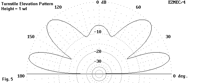
As the antenna is raised further to about 1 wavelength in height, the upper lobes decrease their angle and equalize with the lower lobes. See. Fig. 5. The 1 wavelength height might be considered a dual-purpose antenna, with lower lobes for DX and higher lobes for short skip.
As you raise the antenna further--to the 1.25 to 1.5 wavelength region--a new third lobe makes its appearance. Again, the new lobe is initially straight up. A simple dipole at this height would show its major strength in its lowest lobe. However, the dual dipole arrangement of the turnstile places maximum gain in the new lobe, although the difference in strength among lobes is much less than at the 3/4-wavelength height.
The lobe formation characteristics of the turnstile are simply one of its limitations. For lower HF use, most wire dipole arrays will be 1/2 wavelength or lower, a fact that eliminates the limitation. Heights up to about 5/8 wavelength tend to be ideal. For upper HF use, a height of just about 1 wavelength may be best: that height will equalize the lobes and provide dual skip performance.
The turnstile has other limitations as well. It is essentially a monoband antenna, since the phasing line is specific to a narrow frequency range. Operating the antenna on other bands is possible with a parallel feedline and an antenna tuner. However, with the phasing line in place, the patterns will be erratic.
One possible solution to this problem is to install a relay switching system at the feedpoint for bands other than the fundamental frequency to which the dipoles are cut. One can remove the phasing line and use either dipole to provide fairly standard patterns on frequencies higher than the fundamental. One more switch position for the relay system might permit switching from one wire to the other to obtain the strongest signal.
In fact, this system might also be useful at the fundamental frequency. Having omni-directional reception would allow you to hear signals that would disappear in the end-nulls of a single dipole. Then, switching whichever dipole provides the strongest signal might improve contact ease by up to about 2 dB (or nearly half an S-unit as meters are usually calibrated).
Construction of the turnstile will be largely a matter of the materials used. Wire construction will require special attention to the weight of two coax lines at the junction. For this kind of application, copperweld strength is recommended. For upper HF use, aluminum tubing becomes a possibility, and this type of construction usually involves a central mast. To mount the antenna elements, you can use a plywood or Lexan plate--or even crossed 2x2s (weather sealed, of course). Dipoles can be mounted on opposite sides of the plate or cross--or they can go on one side if the feedpoint ends are separated to prevent contact.
Adding a relay box requires attention both to securing it well and to weatherproofing the box. Of course, a set of control lines to activate the relays will be needed as an added cable weight to the pair of coax lines already noted.
Tuning up the turnstile system requires some care. Begin by adjusting a single dipole for resonance and then add a second dipole of identical construction. There is an important reason for this procedure, based on the properties of the two dipoles when phased by 90 degrees.
The feedpoint impedance of properly adjusted turnstile dipole pairs is just about 36 Ohms. This value yields an SWR between 1.3:1 and 1.4:1 at the feedpoint. Normally, we try to reduce the SWR to the lowest possible value. Do NOT use this procedure with the turnstile.
The turnstile exhibits a very broad stable feedpoint impedance. When properly adjusted, the antenna will easily cover any of the ham bands, including all of 10 meters. So SWR is only an indicator that you have made all of your connections properly.
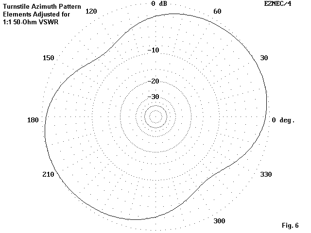
What becomes unstable as the antenna is operated at frequencies up to 3% or 4% away from the design frequency is the omni-directional pattern. It is possible to lower the operating frequency until you obtain the lowest 50-Ohm SWR. Equivalent to this move is shortening the dipole elements until you get the same result. Unfortunately, in the process, you will have lost the omni-directional pattern--as well as the ability to operate each dipole independently at a low SWR.

Fig. 6 shows the azimuth pattern of a turnstile adjusted for the lowest possible 50-Ohm SWR. The side nulls are now deeper than 6 dB, partially cancelling the advantage for which we wanted to use a turnstile. (If one reverses the connections at one end of the phasing line, then the pattern will tilt in the other direction.) Unfortunately, this condition yields no significant added gain to the main lobes, so it is not a substitute for the suggested switching system for using the dipoles independently after locating a desired signal.
The best procedure for constructing the turnstile is the one recommended, starting with a single dipole. When both are in place, carefully cut the phasing line, and then add the main feedline--plus any desired switching system. This procedure will prevent inadvertent loss of the antenna's omni-directional properties.
There are other temptations to avoid. One prominent one is to bend the outer ends of the dipoles to form an incomplete square along the perimeter--in an effort to save space. Moves like this will also ruin the omni-directional pattern, since the radiation from the bent wire ends will partially cancel the necessary radiation balance. Once more, the pattern will degrade into something like the one in Fig. 6. If a bi-directional pattern is what you need, a single simple dipole will do the job better.
Likewise, avoid making the turnstile into an inverted Vee. At downward angles between 30 and 45 degrees, you would need to use a 50-Ohm phasing line, and the feedpoint impedance will drop into the 20-25-Ohm range. As well, the gain from the antenna will decrease. If some shortening of the elements is necessary to fit a given space, the best procedure appears to be to equally fold down the ends of each dipole.
The turnstile is not a magic answer to every horizontally polarized antenna need. Instead, it is one answer to a special need for omni-directional patterns for either transmitting or receiving in a specific frequency band. Among all of the schemes designed to achieve omni-directional radiation with maximum efficiency, the turnstile has one of the very best patterns, along with the simplest construction. Perhaps we have consigned it to the annals of VHF history too long and have forgotten that it is a design that is equally adept at fulfilling HF needs as well.
Improving the Match
Since the appearance of the turnstile note, I have received suggestions for improving the match of the antenna from the present 36-Ohm value encountered by the 50-Ohm coax line. One system came from Leland Scott, KC8LDO, in the form of a useful MathCAD worksheet. See Fig. 7 for the outlines of the basic scheme.

The "short cable" will be 1/8 wl long for a pair of resonant dipoles. The "long cable" will be 3/8 wl long. (If the antenna feedpoints presents some reactance, the requisite lengths will be offset from the 1/8 and 3/8 wl figures used for resonant individual dipoles.) Both are RG-62, a 93-Ohm cable with a velocity factor of 0.86. The differential in cable length maintains the 1/4 wl phasing between dipoles. In addition, it provides a pair of impedances at the junction between the two cables and the main line of about 100 Ohms. The 1/4 wl differential in length yields conjugate reactances which cancel when connected in parallel. The resulting impedance presented by the parallel cables is exceptionally close to 50 Ohms resistive. The short cable is 3.71' and the long cable is 11.13' for a 28.5 MHz design frequency. Models of the antenna using this system show a maximum SWR of about 1.16:1 over the span from 28 to 29 MHz. Relative to the version using a single 72-Ohm phasing line, the only drawback to the system that the models suggest is a slightly higher noncircularity to the patterns. The maximum to minimum gain span averages about 3.34 dB, compared to 2.12 dB for the 72-Ohm phase-line model. It is unlikely that the degree of increased non-symmetry would be operationally noticable.

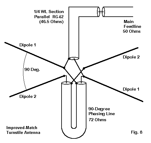
It is also possible to improve the match of the original model without disturbing the phasing or the pattern by using a 1/4 wl section composed of paralleled pieces of RG-62, as shown in Fig. 8. The 7.42' section of parallel RG-62 has an impedance of about 46.5 Ohms. The impedances presented to the main 50-Ohm feedline range between 56.5 and 60 Ohms, with virtually no reactance, for a maximum SWR of 1.2:1 in the 28 to 29 MHz range.
Further possibilities exist for improving the match of a turnstile to a 50-Ohm cable without upsetting the near-circularity of the pattern, for example, the series matching techniques described by Regier and outlined in another note in this collection. Whatever scheme is used, it is first crucial to establish correct phasing for the most circular pattern possible and then to become concerned with matching the unit to a given main feedline characteristic impedance. For non-symmetrical patterns, there are likely better antenna choices available.
Updated 03-06-2000. © L. B. Cebik, W4RNL. This item appeared in AntenneX, January, 2000. Data may be used for personal purposes, but may not be reproduced for publication in print or any other medium without permission of the author.