
Horizontal antennas include such old friends as the center-fed resonant half-wavelength dipole, the inverted Vee variant, and a host of similar antennas. Recently, it was discovered that we could use versions of MININEC and NEC-2 to model what might happen if, in addition to the horizontal wire, a portion of the feedline also radiated. The general modeling procedure was to drop a quarter-wavelength vertical wire down from the normal feedpoint (braid side) to simulate radiation from the outer surface of the braid. The physical analog to this model has been the installation of a line isolator ¼ wl down the coax.
Unfortunately, the model wire antennas emerging from these exercises appear to have gathered more acronyms and call-sign labels than careful analysis. Full modeling details have rarely been given, and results are hardly replicable. However, even if the models can be replicated, there remain strong questions about whether the models are adequate representations of the realities of antenna construction and installation. In short, it is dubious whether anything near the modeled performance can be achieved with real wire antennas. It may be instructive to examine some of the modeling techniques involved in promoting vertical radiation concepts.
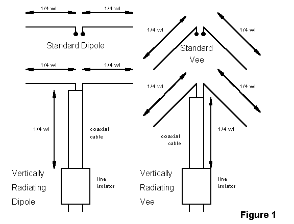
Vertically radiating horizontal antennas presume that the current originating on the inner surface of the coaxial cable braid will divide between the antenna wire attached to the braid and the outer surface of the braid. Also presumed is the idea that this outer surface is somehow floating, being too distant from an earth or system ground to be considered grounded, but having no other currents on it other than those developed as a result of the antenna-feedline junction. This permits the outer surface of the braid to act as another antena wire. A line isolator--usually a device similar in principle to a W2DU ferrite-cores-over-a-length-of-coax--is installed ¼ wl down the coax braid and terminates the radiating section of braid. The result is a current of full strength along the antenna wire connected to the coaxial cable center conductor and a divided current from the inner surface of the braid, part traveling along the antenna wire and part along the outer surface of the braid.
Since the outer surface of the braid is vertically oriented, the dominant polarization of its radiated field is vertical, with a consequential lowering of the overall radiation angle of the antenna's total pattern and a reduction in the front-to-side ratio of the antenna. If a wire dipole or inverted Vee exhibits something like a figure-8 or a peanut-shaped pattern, the vertically radiating versions of the same antennas are reported to exhibit oval or nearly round azimuth patterns.
If we accept all the premises of this scenario for the moment, it is possible to model both standard and vertically radiating dipoles and Vees using common materials and conditions, and to make a comparison between the resultant antennas patterns taken under identical modeling conditions. Let us choose copper wire, perhaps #14 as a commonly used size. Let us also select average earth as the soil under the antenna with a conductivity of 0.005 Siemans/meter and a dielectric constant of 13. These initial choices reflect how such antennas will actually be used, since few, in any, hams have access to lossless wire and perfect ground beneath the antenna.
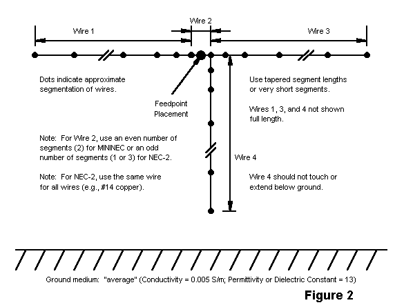
In constructing our models, we may choose either MININEC or NEC-2 (since NEC-4 is just now becoming available, but at a price beyond the means of most amateurs). NEC-2 has some limitations in this exercise, since it requires a separate wire to which one applies the source, which is centered in the added segment. This short segment must meet adjacent segment length requirements of the program, which enlarges the number of segments in the total model if the feed wire is to be kept short. However, to reduce the number of segments, one may taper the segment lengths shorter toward the feed wire to maintain recommended ratios of adjacent wires. Additionally, the vertical wire must be about the same diameter as the antenna wire, since NEC-2 outputs become unreliable when wires of different diameter are joined in many modeling situations. However, NEC-2 includes a higher quality ground analysis system.
MININEC can handle wires of different diameter, but it is not without its own restrictions. First, for reasonable accuracy, segment lengths should be tapered when wires join at tight angles, and a right angle qualifies. Second, one must be careful with the placement of the source. MININEC sources are applied at one or the other end of a segment, which end must attach to another segment or wire. The end of the first wire is not a permitted source point if multiple junctions are present. Likewise, the junction end of the down wire is not a permitted source point, since it does not reflect the series connection of the coaxial cable to the horizontal wire, but instead treats the down wire as one side of the antenna and both sides of the horizontal portion as the other side of the antenna. One solution is to add a 2-segment wire as a feed point, placing the feed at the end of one segment within the wire. Additionally, one may also taper segment lengths within the wires as they approach the feed wire to ensure that adjacent wires meet program rules. Since MININEC has only a limited accuracy ground system, dropping the vertical wire below 0.2 wl above ground without creating a true ground-mounted vertical antenna may strain MININEC limits.
Figure 2 illustrates some of the salient points of NEC-2 and MININEC models of a vertically radiating dipole.
The next question concerns the frequency of operation, which has implications for wire length and the height of the assembly above ground. With a quarter wavelength of vertically oriented coaxial cable setting a minimum height, I decided against 80 meters. The antenna would have to be a minimum of 68-70' above ground. More typical amateur heights range from 35 to 50' above ground. Therefore, the test frequency selected was 7.15 MHz. Antenna heights for models could then range from 35' to 50' for the horizontal section, with the bottom of the vertical section ranging from about 1' to 15' above ground.
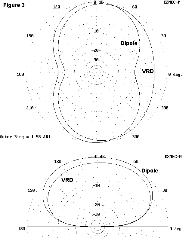
Elevation patterns provide a general indicator of an antenna's gain when directed in the azimuth bearing of maximum radiation. Since low angle radiation has been one of the claimed hallmarks of the vertically radiating horizontal antenna, an elevation angle of 20 degrees has been chosen for the azimuth patterns. Figure 3 shows comparative patterns between a standard dipole and a vertically radiating version at a 35' height. These patterns happen to be taken with NEC-2, but are not significantly dissimilar to patterns taken with MININEC.
        A Comparison of Three Modeled Vertically Radiating Dipoles

MININEC model: all #14 copper wire over average MININEC ground; with
tapered segments to a short 2-segment feed wire.  Horizontal length: 67';
vertical length: 33.5'

Height    Gain at 20°    Azimuth angle  Maximum   Take-off  Feedpoint
(feet)    in dBi         of maximum     gain-dBi  angle     Impedance
                         radiation                          (R +/- jX)
50'       3.05           79°            4.98      38°       63 - j14
45'       2.35           78°            4.75      42°       66 - j8
40'       1.73           76°            4.66      48°       67 + j1
35'       1.17           75°            4.57      55°       61 + j13

MININEC model: #14 horizontal copper wire with 0.5" vertical copper wire
over average MININEC ground; with tapered segments to a short 2-segment
feed wire.  Horizontal length: 67'; vertical length: 33'

Height    Gain at 20°    Azimuth angle  Maximum   Take-off  Feedpoint
(feet)    in dBi         of maximum     gain-dBi  angle     Impedance
                         radiation                          (R +/- jX)
50'       3.11           79°            5.07      38°       64 - j15
45'       2.41           78°            4.85      42°       67 - j9
40'       1.79           76°            4.76      48°       68 - j1
35'       1.24           75°            4.70      55°       62 + j11

NEC-2 model: all #14 copper wire over average Sommerfeld ground; with
tapered segments to a short feed wire.  Horizontal length: 67'; vertical
length: 33.5'

Height    Gain at 20°    Azimuth angle  Maximum   Take-off  Feedpoint
(feet)    in dBi         of maximum     gain-dBi  angle     Impedance
                         radiation                          (R +/- jX)
50'       3.51           79°            5.42      38°       57 - j11
45'       2.76           78°            5.15      42°       60 - j7
40'       2.02           77°            4.94      48°       61 - j1
35'       1.19           77°            4.66      56°       59 + j9

Note: NEC-2 and MININEC models using short segments rather than tapered
segment lengths do not differ significantly from the figures presented for
these models.  All models at all heights exhibit the same kidney-shaped
azimuth pattern.

Table 1.  A comparison of three modeled vertically radiating dipoles.
Obvious in Figure 3 is the displacement of the narrowed portion of the azimuth pattern toward the horizontal arm connected to the braid, relative to the overlaid pattern for a dipole. Overall gain in the most favored direction of the antennas is similar to that of a dipole, as is the overall gain to the sides (off the antenna ends). The latter is simply displaced. Nowhere does there appear the grand ovals and circles of omnidirectionality advertised for the vertically radiating antennas. Indeed, there seems to be a misconception about low standard dipoles, to the effect that they are exclusively horizontally polarized antennas. To dispel this misconception, Figure 4 compares the field components of a standard and a vertically radiating dipole azimuth pattern. Although the vertically radiating version shows naturally significantly greater vertically polarized radiation, the standard dipole has a significant amount that contributes to the broadening of the free space Figure 8 into the mere shell of a peanut.
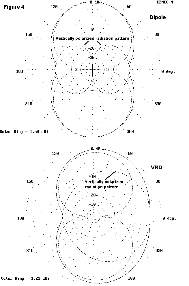
Within these modeling strictures, which attempt to use modeling program features to replicate reality to the degree to which the programs are capable, there appears little to choose between the standard and the vertically radiating versions of the dipole. The displacement differential off the ends of the antenna would be difficult to detect in actual operation, even using antenna range A-B testing techniques. However, that differential might prove marginally useful to someone with certain QRM problems.
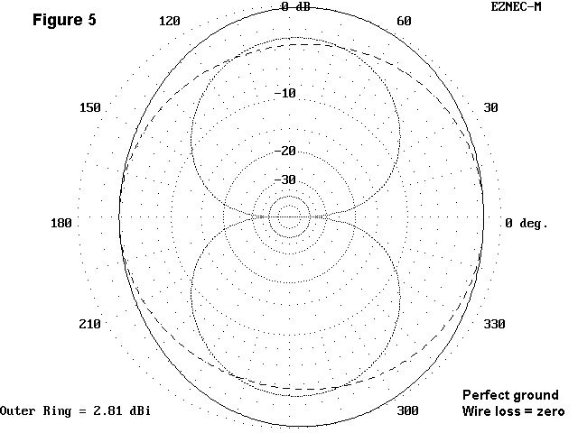
Why do these patterns differ so radically from some which claim oval or nearly circular radiation patterns for vertically radiating antennas? The answer lies in certain dubious modeling practices. One of these is the assumption of perfect ground under the antennas. (Some claims for 80-meter VRDs use the almost as rare very good or excellent ground.) This assumption permits the vertical portion of the antenna to seemingly radiate with much greater efficiency in models than a user is ever likely to achieve, even with a radial system under the antenna. Another is the use of lossless wire. A third is the selection of some precise distance of the vertical wire above ground, thereby optimizing conditions as no real user is likely to be able to replicate. These factors do not include obvious violations of the modeling constraints of the available programs, as noted earlier. Figure 5 shows what illusions may be wrought from unrealistic modeling.
When modeled as close to reality as MININEC and NEC-2 will permit and within program constraints, vertically radiating dipoles and Vees do not constitute radical departures from standard versions of these antennas. Rather, they represent predictable pattern distortions that may be of some use to some operators under some conditions. However, questions about modeling adequacy are only one aspect of the inquiry. There are some significant questions to be raised about the physical means be which a vertically radiating dipole or Vee is to be implemented.
I fear that many an investigator pursuing vertically radiating
horizontal antennas has been fooled by antenna modeling possibilities into
accepting uncritically the reality, regularity, and reliability of what
adding an extra wire to a dipole seems to show under tenuous modeling
assumptions. Until there emerges a more adequate analysis of the reported
and modeled phenomenon, the vertically radiating horizontal antenna likely
deserves to be set aside as an interesting example of unsatisfactory
antenna modeling.
Updated 3-15-97 © L. B. Cebik, W4RNL Data may be used for personal purposes, but may not be reproduced for publication in print or any other medium without permission of the author.