
 Notes on Calculating Input Values from Load Values
 The input values of voltage, voltage phase angle, current, current phase angle, resistance, and reactance (along with impedance and impedance phase angle, if desired) depend upon two properties: the load value of these parameters and the length and characteristics of the transmission line. The load may be an antenna, a junction with one or more other transmission lines, a dummy load, or anything similar. Those with little experience in dealing with these concepts and quantities may be interested in reading the following review of the relationships among the various transmission line properties.
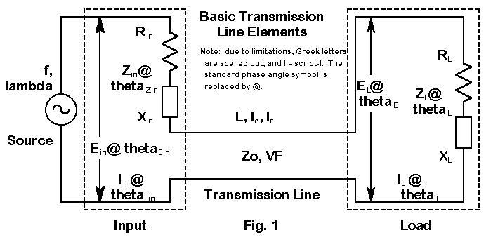
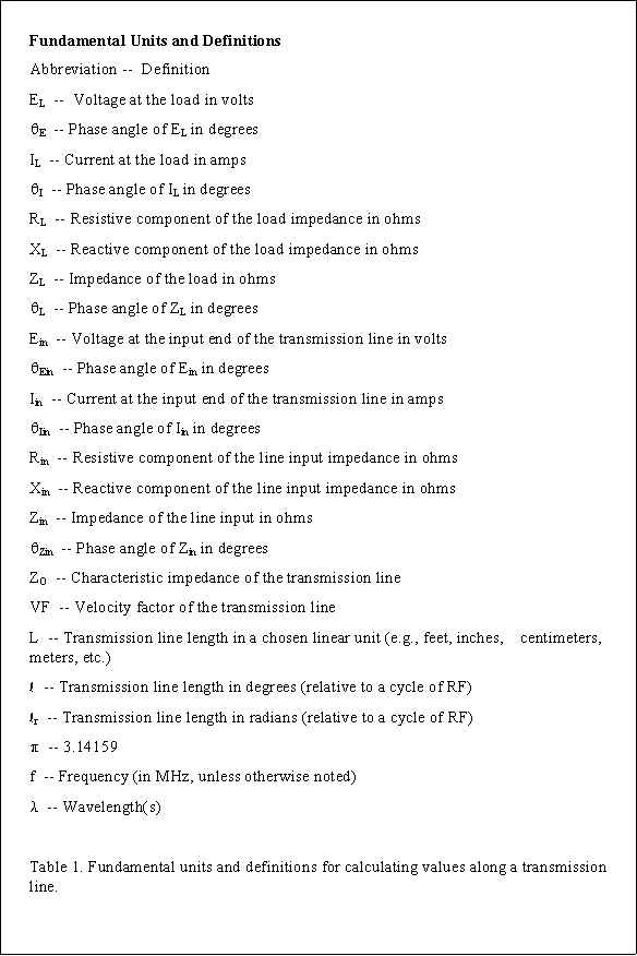
Everything begins by speaking the same language. Figure 1 schematically represents most of the elements of transmission lines, while Table 1 (at the end of the text) defines many of the abbreviations to be used in the text and the equations to follow. Since all calculations will be done in terms of degrees (or radians) along a wavelength of RF, let us note in passing the standard conversion equations:
and
where Lm is the initial length in meters and Lf is the initial length in feet. The constants can be rounded to 1.2 and 0.366 respectively, but I usually prefer to save rounding for the last step in a series of calculations, despite the predilection of many to initially round everything to the smallest number of significant figures to be found in the data group.
Should you wish to write a basic program incorporating any of the material to follow, you will have to convert degrees into and out of radians. For quick reference, the conversion equations are these:
and
where thetad is any angle (or l) in degrees, and thetar is any angle (or l) in radians.
Impedance Transformation
Let's begin with the transformation of impedance along the transmission line, beginning at the load. For every degree of travel, the impedance takes on a new value, with one exception. If the load is purely resistive and exactly matches the characteristic impedance of the line, then the impedance along the line is constant. However, if the load has any reactance or if the load does not match the characteristic impedance of the line, then resistance and reactance go through a cycle of changing values that repeat themselves every 180°. All of what follows, of course, applies to lossless lines, which provides accurate enough results for the short lengths involved in most amateur applications.
Terman (Radio Engineer's Handbook, p. 186) provides the most general impedance equation:

where l is the length of the line and lambda is the length of a wavelength, both in the same units, that is, both in feet, meters, or degrees. The terms of the equation are therefore in radians automatically.
As a matter of completeness, we should note that Keucken (Exploring Antennas and Transmission Lines by Personal Computer, p. 181) provides the appropriate expansion of this equation for use in a computer:
Keucken's procedure is to calculate the numerator and denominator independently, converting each into polar notation. Zin then equals ZO times the ratio of the polar amplitudes, while the phase angle is simply the numerator angle minus the denominator angle. Rectangular coordinates emerge from standard sine and cosine calculations.
However, it is very often more useful to begin with and end with the resistive and reactive components of an impedance separately given (that is, given in rectangular rather than polar form). The ARRL Handbook for the early 1990s (p. 16-3) provides separate resistance and reactance equations:


Equation 8 will return values with the correct signs, + for inductive reactance and - for capacitive reactance.
To obtain the impedance, simply take the square root of the sum of the squares:
and obtain the phase angle from
From the values of Rin and Xin, we can easily calculate the VSWR using the most general equation:

Since equations (7) and (8) are for lossless lines, the same VSWR value will result from Rin and Xin values taken at any length, from the antenna terminals on down the line. A few sample calculations should convince skeptics who have experienced changes in SWR readings in the shack with changes in line length that those changes arose from factors external to the basic antenna-feedline configuration. Adding loss factors to the Rin and Xin calculations will result in progressively lower VSWR values as the line length increases. Loss amendments or supplements to the basic equations are important at VHF or with very long line lengths at HF, but short HF lines used in many simple matching or phasing solutions rarely need the added complexities for results that are within measurement or construction accuracy limits. To explore the losses along a line and their effect upon VSWR readings, obtain a copy of the program TLA by N6BV, available from the ARRL.
Solving equation (11) for Rin and Xin, of course, will not return unique values. Instead, the equation will return families of values. The families of values--or curves--form the basis for the well-known Smith charts and its more recent computerized extensions, for example, the W7ZOI/ARRL program, MicroSmith.
Stubs
If the load end of the line is short circuited so that RL = 0, and XL = 0, then
and the reactance is inductive. If XL = (an open circuit), then
and the reactance is capacitive. Equations 12 and 13, of course, are the standard equations for calculating the reactance of a length (less than 90°) of transmission line. The results may be obtained directly from equation (8), assuming that it has been plugged into a BASIC program or something similar, by letting RL = 0.00000001 (as a place holder for 0.0, which may yield "Division by Zero" messages) and XL = 0 for inductive, shorted stubs. For capacitive, open stubs, plug 999,999,999 into both RL and XL.
Often, we know the reactance to be cancelled by a stub and desire the corresponding line length. If we let lL = the length of an inductive stub (in degrees) and likewise let lC = the length of a capacitive stub (in degrees), then the equations become
and
The terms of equation (15), of course, can be inverted and the arctan taken of the result, a procedure common to calculator operations. To determine the physical length of the transmission line, apply equations (1) or (2), solving for Lf or Lm, as appropriate.
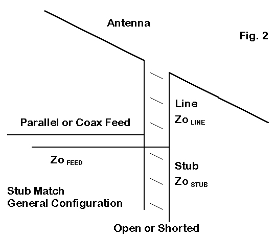
Although we may apply stubs wherever compensatory reactance is required in an antenna-feedline system, the more general stub matching situation is presented in Figure 2. Here, we introduce a transmission Line between the antenna and the junction of the Feed line to the shack or rig. (Capitalized words here refer to elements in Figure 2.) The length of Line is chosen so that at the junction, the resistive component will be the same as the characteristic impedance of the Feed line. However, in most instances, there will be also be a reactive component which the addition of a parallel stub cancels. Note that under the condition of no series reactance, the series and parallel values of feedpoint impedance are identical and purely resistive. In the most general situation, there is no requirement that the Line, Stub, and Feed sections have the same characteristic impedance.
Although calculation of line length for the Line and the Stub have been largely left to graphical solutions, there is no reason why we should not directly calculate them, especially via a short computer program. The Line length calculation simply requires us to solve equation (7) for l and to convert that length in radians into degrees and feet via equations (1) through (4) as appropriate. The rewrite of (7) yields a quadratic:

Solving for lr, we obtain

Note that there are two solutions, since for every 180° of line length (under mismatch conditions), there will be two points at which the resistive component has the same value. Applying equation (8) to the two lengths will yield opposing values of reactance. The limiting case is where the value under the radical goes to less than zero: this condition indicates that with the combination of line values chosen for the antenna values measured or derived from a modeling program, the resistive component never reaches the chosen Feed line characteristic impedance.
Converting the remnant series reactance into a parallel value provides the magnitude, with a sign change, that the stub reactance must equal to leave the junction with a purely resistive impedance that matches the Feed line ZO.
This excursion into stub-matching calculations simply illustrates the utility of equations (7) and (8). Knowing the impedance at the end of a length of a feedline terminated in a load, a short, or an open-circuit has too many uses to catalog here.
Current and Voltage Transformation
A knowledge of resistance and reactance along a transmission line will not answer every important question about a feed system. Often neglected are the classic and very useful equations for calculating the voltage and current, along with their respective phase angles, along a transmission line. Terman (p. 185) gives the basic current equation as
where l and lambda have the same meaning as with equation (5).
Note that the calculation of current at any point along a transmission line requires knowledge not only of the current and its phase angle, but as well of the voltage and its phase angle. Such information, if not measured, best comes from information provided by antenna modeling programs, which generally collect together EL, thetaE, IL, thetaI, RL, and XL in one listing or report. Although such data comes from a model and is often limited by being calculated over perfect, rather than real, ground, it may turn out to be more accurate than the output of the measuring instruments found in most ham shacks.
Expanding the Terman equation for load currents and voltages that are at other than a 0° phase angle, we can first let ratio EL/ZO = IZ. Then,
and
Substituting into equation (18), we arrive at the most general equation,
Let IH be the "real" component solution and IJ be the "j" component solution. Then
and
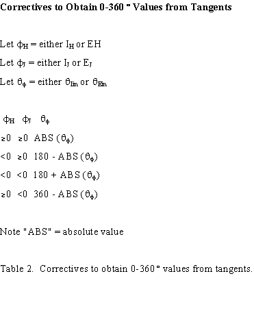
Unlike reactance that varies ±90°, the phase angle of the current along a transmission line varies through a 360° cycle. Since tangents are ambiguous, a corrective is in order, especially if these equations are loaded into BASIC or some similarly restricted language. Table 2 provides a set of general correctives applicable to either voltage or current calculations.
The Terman (p. 185) equation for finding the voltage anywhere along a lossless transmission line is
Letting ILZO = EZ, expanding, and then gathering terms, we arrive at an equation exactly comparable to (21), and we proceed as in (22) and (23) to arrive at Ein and thetaEin. Likewise, the correctives in Table 2 are required to follow the voltage phase angle through its 360° swing.
Equations (7), (8), and (19) through (24) can put into a single program for simultaneous calculation for any specified collection of voltage, current, and impedance conditions at the load of a transmission line. To prevent division by zero, do not let IH or EH go to 0, but make it read some tiny fraction, such as 0.00000001. Likewise, force IJ and EJ to zero if either is between 0.001 and -0.001.
Given an operating frequency and the characteristic impedance and velocity factor of a transmission line, you can calculate the voltage, current, and impedance conditions for any length of line. Likewise, with a simple "FOR-NEXT" loop, you can produce a screen or a page of values to explore rates of change for any of the values. A very few such sheets will convince the hardiest skeptic that with complex loads, neither voltage nor current nor their phase angles change in symmetrical sine curves associated with basic AC theory. In general, values from 0° to 90° in 5 increments just about fill a monitor screen, while 0° to 180° in 5 increments will almost fill a sheet of paper. For paper printing, you can simply plug in the values on the 180° line for a new run to complete an entire cycle. One of the easiest ways to check the accuracy of the equation transcriptions into the programming language is to add phase angles thetaZ and thetaI; they should equal thetaE, although you may on occasion have to subtract 360° from a sum to arrive at values of thetaE that have started a new cycle. You can also spot check amplitude values with Ohm's law, although it may require calculation of Zin from Rin and Xin, if Zin is not part of the charted values.
Feedpoint Conditions
(Note: equations 25 through 27 have been omitted from this version of the presentation, since they deal with a specialized application and are less generally useful.)
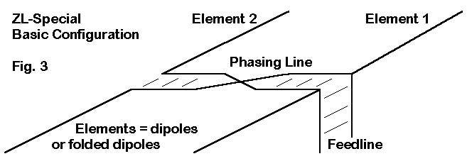
2-element arrays, where the forward element is directly driven, require a phasing line that has a half-twist between two driven elements. In the case of the ZL Special, the line is approximately 45° long with respect to transformation of the current, where the half-twist in effect places the rear element current 180° minus the line length (45°) out of phase with respect to the forward element current. The net effect is a reversed rear element current 315° (or -45°) out of phase with the forward element current. The general ZL Special configuration appears in Figure 3. We shall limit our interest in the antenna to the feedpoint conditions.
The input end of the phasing line for the 2-element horizontal array is in parallel with the forward element source. At this point, the voltage is the same for each branch of the current division, although the currents themselves may be quite different. If we calculate or derive from antenna modeling software the phase line input impedance and the forward element impedance, they will be given in series form. To obtain a single source impedance for this antenna, we shall require 1. a transformation to parallel values, 2. a parallel combining of the two, and 3. a return to series form for obtaining the feedpoint impedance of the combination relative to any feedline connection.
Converting the pair of series impedances into parallel form requires the standard conversion equations:
and
It is usually arithmetically easier to invert these values into conductance and susceptance values, each parallel component of which may be added for a combined value and then to invert each result to obtain the parallel values for the resultant resistive and reactive components of the feedpoint impedance. Finally, use these standard equations to reconvert the combination to series form:


The calculations associated with feedpoint impedances of a horizontal 2-element array are amenable to BASIC and other utility program languages.
This exercise has aimed to demonstrate the mathematics of calculating feedline input values from load values for any transmission line and of calculating the length of matching stubs, along with the feedpoint impedance of rudimentary arrays. None of the equations are in any sense new, although only a few of the crucial ones--for example, those involving values of current and voltage, along with their phase angles--appear in any of the current handbooks readily available to radio amateurs. Once there was a point to these omissions, since Smith charts obviated some (but by no means all) of the tedious hand calculations. Without diminishing the utility of Smith charts, even the most rudimentary form of programming--that is, BASIC--can reduce the work of making direct calculations down to a matter of inputting data. Moreover, familiarity with the equations provides insight into what the Smith Chart is doing and how. Thus, it is perhaps time once more to place these very useful equations before the amateur community in readily available form for use by the ham interested in antennas and feedlines.
Most of the equations cited in this set of notes have been placed into utility programs among the
HAMCALC collection, developed and regularly updated by George Murphy, VE3ERP. Since the collection of
programs uses GWBasic, the equations (or their break down for implementation) is readily accessible to
interested users. The latest version of HAMCALC as of the date of converting these notes to HTML is 37.
Although older versions of HAMCALC appear on bulletin boards, a current version can be obtained directly
from Murph. His address is 77 McKenzie Street, Orillia, ON L3V 6A6, Canada. Murph requests $5.00 to
cover the cost of materials and shipping, and you will be added to his mailing list as a registered user.
You may, however, distribute copies of HAMCALC freely.
Updated 11-25-98. © L. B. Cebik, W4RNL. Data may be used for personal purposes, but may not be reproduced for publication in print or any other medium without permission of the author.