
 I Want to Build a 3-Element Yagi
Those of us with more time than money get the urge to upgrade our antennas from dipoles to beams in the home workshop. The logical first step might be a 2-element Yagi. Often, we skip this step because we have heard or seen evidence that 2-element Yagis do not quite have the specifications we want. If we make use the common reflector-driver design, the gain is low and the front-to-back ratio is poor. If we opt for a driver-director design, we get more gain and better front-to-back ratio, but a very narrow beam width and a potentially very low feedpoint impedance. So we immediately jump to 3-element designs.
Our next step is usually a semi-fatal one. We search the magazines and handbooks on our shelves for a design that looks like one we can build. We know what the author claims the beam will do, but we are not ever sure of how it does what it is supposed to do or whether our version is doing the same thing.
So let's back up a bit and look at some 3-element Yagi basics. I shall focus on monoband beams, because they are much easier than multi-band beams to model and to build so that their performance matches the model. Even if you have your heart set on buying a tribander, perhaps these basics will help you better to understand both the antenna maker's claims and the performance you actually get.
The basics I have in mind have little to do with the theory of parasitic element operation. The ARRL Antenna Book and some references I shall mention along the way do a good job at that level of explanation. Instead, I shall begin in the middle of things with some distinctions among Yagi designs. There are so many Yagi designs floating around today that they can be at first sight a bit bewildering.
High Performance Designs
The first decision we have to make is whether we wish to have a wide-band Yagi or a high-performance Yagi. Let's begin with the high-performance designs, since these have very great initial appeal. We shall return later to some wide-band designs.
Once we have opted for a high-performance design, we have to figure out what we mean by that term. First, there is the matter of size. The element lengths will not vary by a large amount from one design to another (but they will vary significantly in terms of the performance). So, size turns out to be a question of boom length.
James Lawson, W2PV, developed most fully the notion that the gain of a Yagi is highly dependent upon the boom length. His book, Yagi Antenna Design, has become one of the classic references for those interested in basic Yagi theory. Based on his work, many designers have optimized 3-element Yagis of various lengths for maximum performance.
Maximum performance is a balanced mix of high gain, good front-to-back performance, and a satisfactory feedpoint impedance. Let's work backwards through the list.
For almost any length boom, one can get a little more gain from a Yagi by so spacing and sizing the elements that the feedpoint impedance drops to about 10 Ohms or less. Most high performance designs you will encounter tend to opt for feedpoint impedances closer to 25 Ohms. The reasons are many, but one good reason is a matter of losses. Suppose that the total resistance of all the connections at the feedpoint, including those of a matching system for 50-Ohm coaxial cable, amount to 1 Ohm. (That is a quite high value and can be reduced by good construction practices.) With a 10-Ohm feedpoint impedance, about 9-10% of the power is going to heat. If the feedpoint impedance is 25 Ohms, then the loss is closer to 4%.
To this consideration, we can add the fact that it is generally easier to design low-loss matching systems for a 25-to-50 Ohm conversion than for a 10-to-50 Ohm conversion. So 25 Ohms becomes a kind of de facto (but not absolute) limit to a Yagi's feedpoint impedance.
For the higher feedpoint impedance, it is also somewhat easier to design a 3-element Yagi whose gain and front-to-back performance figures hold up across such HF bands as 20 and 15 meters--as well as the first MHz of 10 meters. As well, the designs can be replicated in the home shop with moderate building skills and are not so finicky as to require industrial laser measuring equipment in setting the dimensions.
Within these constraints, then, lets look at three good designs for 3- element Yagis.
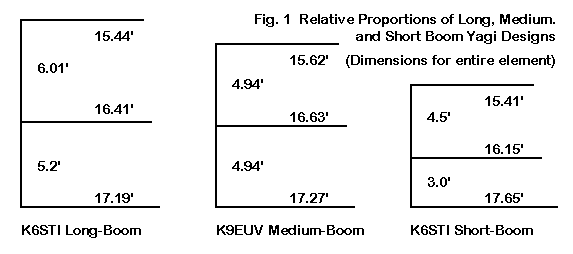
As revealed in Fig. 1, the designs I have in mind use three different boom lengths. The long-boom design, shown for 28-29 MHz, is adapted from an optimized design by K6STI. It uses an 11.31' boom, which is nearly 1/3 wl long. The K9EUV design uses a 9.88' boom, and has the additional feature of using equal spacing between elements. (A fourth director element at the same spacing and the same length as the present director provides good 4- element Yagi performance.) The third design is a short boom Yagi, also by K6STI, that requires a 7.5' boom. For construction, you should round these boom-length numbers upward to the next whole foot to provide room for mounting plates and hardware. So we have 12, 10, and 8 foot boom 3-element Yagis.
Caution: Do NOT build these designs as given here. They all use uniform diameter elements. Converting them to the actual lengths needed by physical designs that employ tubing that decreases in diameter will net us different dimensions. But that is a subject for a future episode.
The 10-meter designs all use 0.5" aluminum tubing. We can scale them for any band in the following way. Take the ratio of the new design frequency (for example 14.175 or 21.22 MHz) to the present design frequency (28.5 MHz) and invert it (since lower frequencies will require longer, fatter elements). Now multiply the element lengths, the element spacings, and the element diameters by this figure.
As a sample, here is a collection of dimensions for the three basic designs for 10, 15, and 20 meter versions of the antenna.
Long-Boom
Frequency (MHz)          28.5                21.22               14.175
Element Lengths (feet)
     Reflector           17.90               23.11               34.56
     Driver              16.41               22.06               33.00
     Director            15.44               20.76               31.05
Spacing (feet)
     Ref-Driver           5.2                 6.99               10.46
     Driver-Dir           6.01                8.08               12.09
Element dia. (inches)    0.5                 0.75                1.0

Medium-Boom
Frequency (MHz)          28.5                21.22               14.175
Element Lengths (feet)
     Reflector           17.27               23.20               34.72
     Driver              16.63               22.34               33.43
     Director            15.62               20.99               31.41
Spacing (feet)
     Ref-Driver           4.94                6.63                9.92
     Driver-Dir           4.94                6.63                9.92
Element dia. (inches)    0.5                 0.75                1.0

Short-Boom
Frequency (MHz)          28.5                21.22               14.175
Element Lengths (feet)
     Reflector           17.65               23.73               35.50
     Driver              16.15               21.71               32.47
     Director            15.41               20.71               30.98
Spacing (feet)
     Ref-Driver           3.00                4.03                6.03
     Driver-Dir           4.50                6.05                9.05
Element dia. (inches)    0.5                 0.75                1.0
Clearly, I have violated my own scaling scheme by using the closest standard value of aluminum tubing as the element diameter. Hence, some very small adjustments are required in the element lengths and spacings, but generally, these are too small to make an operational difference. Nonetheless, some of the difference shows up numerically in the design frequency performance figures for the three designs. Here the table divides the designs by bands.
20-Meters:  14.175 MHz
Antenna Design           Free Space          Front-to-      Feed Impedance
                         Gain dBi             Back dB       R +/- jX Ohms
Long-Boom                8.11                27.31          25.71 - j 0.93
Medium-Boom              7.78                35.50          27.02 + j 0.50
Short-Boom               7.13                41.35          27.46 + j 0.01

15-Meters:  21.22 MHz
Antenna Design           Free Space          Front-to-      Feed Impedance
                         Gain dBi             Back dB       R +/- jX Ohms
Long-Boom                8.16                26.12          24.80 + j 0.37
Medium-Boom              7.81                34.88          26.06 + j 0.94
Short-Boom               7.17                61.67          26.56 - j 0.00

10-Meters:  28.5 MHz
Antenna Design           Free Space          Front-to-      Feed Impedance
                         Gain dBi             Back dB       R +/- jX Ohms
Long-Boom                8.11                27.15          25.70 - j 0.80
Medium-Boom              7.80                34.77          26.51 + j 1.69
Short-Boom               7.12                41.66          27.45 - j 0.01
These tables of predicted performance from NEC models show a number of things, including how to be misled. First, the numbers--even though slightly different in the decimal columns--illustrate that for each design, the performance is identical on all three bands. The excess decimals are given because NEC reports them and because they show how little different the performance varies as we correctly scale a beam from one band to another.
However, the front-to-back figures can mislead us into thinking that the short-boom model has an almost miraculously better front-to-back performance than the other beams, as good as they are. The figure given is for the 180-degree front-to-back ratio, which is usually a very convenient figure to obtain. That figure may not be indicative of the performance of the antenna in all its rearward directions.
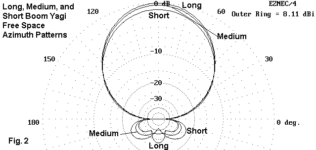
Fig. 2 provides an overlay of the 28.5 MHz free space azimuth patterns of all three antenna designs. We may note the forward gain peaks, which just about correlate to the differentials in boom length. The rear lobes give us much more valuable information. Here we see that the long-boom design has three small lobes of roughly equal size so that the front-to-back ratio in the table gives a fair appraisal of the overall front-to-rear performance. In contrast, the other two models have deeper 180-degree "dimples," combined with much stronger angling lobes. When averaged out, none of the antennas has much of an advantage over the other. Indeed, anything above 20-dB front-to-back ratio overall might be considered outstanding.
To this point, it may seem that the decision we need to make is one of gain advantage vs. mechanical disadvantage to a longer boom. However, let us not be so swift to judgment. For I have once more misled you by giving you the peak or nearly peak performance of the antenna at one frequency. The next question is how each of these designs performs across an entire ham band.
Since the first MHz of 10 meters is the greatest stretch for these designs (because 20 and 15 are proportionately narrower), let's sweep the antennas across the 28 to 29 MHz range and see how the performance of each holds up.
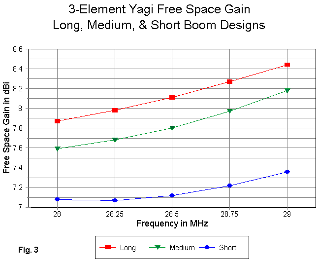
In Fig. 3, we have the gain of the three designs across the pass band. Note that the gain figures in the tables are intermediate values. The gain across the band can vary by as much as 0.4 dB in at least one of the designs. In selecting a design, we must also ask whether the lowest gain--which occurs at the low end of the band for 3-element Yagi designs--is an acceptable figure (when weighed against all of the other factors involved in our decision to build).
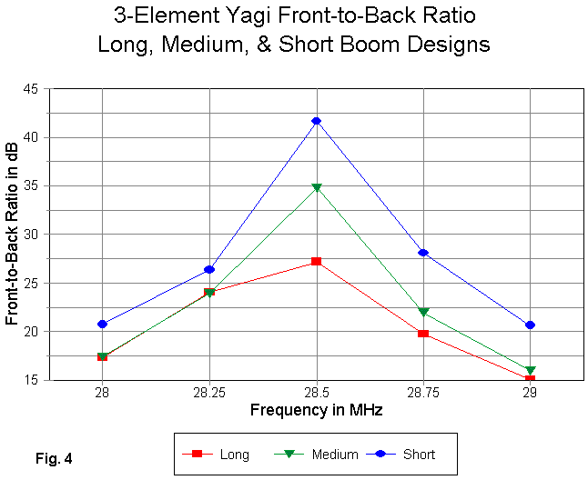
Fig. 4 records the 180-degree front-to-back ratios across the pass band. Here we can either be impressed by the peak values, or we can take a closer look at the values at the band edges. The short-boom design actually excels in this department, with no value falling below 20 dB. The other two designs are remarkably close in their band edge values, which are about 17 dB at the low end and 15-16 dB at the high end. Before settling on a design for the two lower bands, we should remember that these bands are only 68% to 70% as wide as the 10-meter passband. Hence, we can achieve better band-edge results by centering the peaks in our final design.
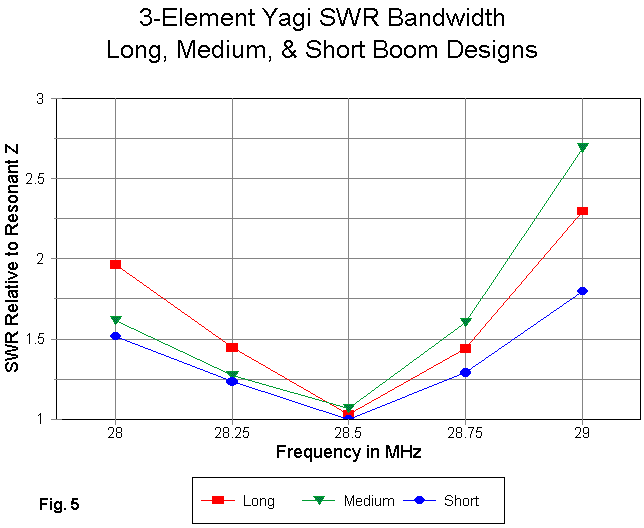
A rough measure of whether we shall be able to effect a wide-band match to a 50-Ohm cable can be derived from the SWR curve of the antenna related to the resonant impedance before matching. Since the feedpoint impedance of all three models is so close to 25 Ohms, we can use that number as representative of the resonant feedpoint impedance. Then we can evaluate the SWR curves in Fig. 5.
For all three designs, the SWR climb more quickly above the resonant design frequency than below it. On 10 meters, this means exceeding a 2:1 SWR value at the upper end of the pass band for two of the three designs. However, all three designs will likely show under 2:1 SWR across the narrower reaches of 20 and 15 meters. The short boom design shows the flattest curve.
Although the designs were set up for a resonant feedpoint impedance (little or no reactance), one can extend or shrink the driver length as necessary to use any of the common matching system: beta, gamma, Tee. Of course, a 1/4 wl section of 35-37 Ohm coax will provide a matching section to a 50-Ohm main line if we leave the feedpoints resonant. We shall look in more detail at typical matching systems before we are done.
So it looks like we are almost ready to make a decision. Seemingly, all we need to do is to look at how the elements might change if we use several diameters of tubing for each one.
Not so fast. We have not yet looked at truly wide-band designs to see if they hold any advantages and what those advantages might be. So while we are still in this preliminary stage of design evaluation, let's look next month at a pair of wide-band Yagi designs.
Updated 07-31-99. © L. B. Cebik, W4RNL. This item appeared in AntenneX, April, 1999. Data may be used for personal purposes, but may not be reproduced for publication in print or any other medium without permission of the author.