
 I Want to Build a 3-Element Yagi
Had the 3-element Yagis we explored in the first two parts of this investigation been designed for VHF, we might have been able to use the dimensions as given. At VHF and above, we often use elements with uniform diameters. However, at HF, the most common practice is to use elements composed of tubing whose diameter decreases as we move outward from the element center. That makes a big difference--perhaps the difference between a beam that works and one that only seems to work.
Tapered-Diameter Elements
The relationship between uniform-diameter and tapered-diameter elements has long been guessed at, but only in the last decade or two has it been fully appreciated. Perhaps the most complete treatment of that relationship appears in David Leeson, W6QHS, Physical Design of Yagi Antennas. Leeson's conversion equations are built into some antenna modeling software (EZNEC and NEC-Win Plus).
When an element in the vicinity of 1/2 wavelength long is composed of materials which taper downward in diameter away from the center point, the required length for resonance increases relative to an element of equivalent uniform diameter. Moreover, the equivalent uniform diameter is not simply the average diameter of the materials used.
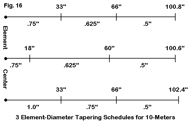
Fig. 16 gives us some examples to explore. Each shows 1/2 of a resonant aluminum element for 28.5 MHz. At the top, the element is roughly equally divided. The second element uses the same sequence of tubing, but in unequal lengths. The bottom element uses the same inner section lengths as the first example, but with a steeper taper.
In this example, and in all element-diameter taper schedules, only the exposed part of each tubing size is shown. Where one tube fits inside another, an additional overlap length of about 3" is generally recommended. Anything more tends to add weight without adding strength, and much less than the 3" overlap may jeopardize junction strength.
The examples show that the required length for resonance changes if we change the relative lengths for a given taper schedule or if we change the taper schedule itself. The following table can make the changes even clearer.
Example   Required       Average   Equivalent     Length of      Feed Z
(Fig. 16) Length in      Dia. in.  Dia. inches    Equiv. El.     R +/- jX
Top       100.8          0.623     0.631          98.58          71.8-j0.1
Middle    100.6          0.634     0.598          98.67          71.8-j0.1
Bottom    102.4          0.742     0.739          98.39          71.8-j0.2
The more radical the taper, the longer the required length for resonance. Variable length sections alter the length and the equivalent uniform diameter. Sometimes the equivalent diameter is close to the average--and sometimes not.
Many home Yagi builders tend to freely substitute materials in a design, unconcerned about the changes in element length that may be required to get the same performance as the original. These same builders often lack any means of checking performance other than an SWR meter. Hence, they assumed that if the antenna has the same feedpoint characteristics as the original, it must yield the same performance. The assumption is very often a bad one.
Without sophisticated antenna test range equipment, the best method available to check a Yagi without any element loading for performance is antenna modeling software. Both MININEC and NEC (the latter with tapered- diameter corrections built in) have been calibrated and tested extensively, and Yagi designs that pass the modeling test generally perform as modeled. There are almost always slight variations between the model and the physical version of the antenna, but in most cases, they are far smaller and less detrimental to performance than the guess work that marked the first 30 years of home Yagi design after World War II.
Let's look at some dimensions for 3-element monoband Yagis using various diameter taper schedules for 10, 15, and 20 meters. The differences from our uniform-diameter study models may be instructive. The following notes will use common US aluminum tubing sizes, which tend to come in 1/8" increments. A common wall size of 0.58" permits succeeding tube sizes to mate closely and still have enough play to slide one within another with ease. Since builders in other parts of the world must work with available sizes, usually specified in millimeters, here is a small table of equivalences.
US Size        Size in mm          US Size        Size in mm
in inches                          in inches
0.375           9.5                1.0            25.4
0.5            12.7                1.125          28.6
0.625          15.9                1.25           31.8
0.75           19.1                1.5            38.1
0.875          22.2                2.0            50.8
Because non-US antenna elements will likely have a different set of element diameter transitions, it is especially important to remodel a Yagi design when changing the element dimensions from English to metric.
Some 10-Meter Designs
We shall look at only two of the many possible element taper schedules one might use for 10-meter beams. See Fig. 17.
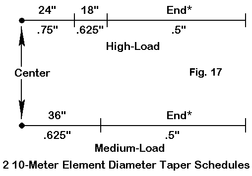
Following the work of K6STI, we shall call the upper schedule the high- loading schedule, because it was thought to be better able to withstand higher winds. The lower version is called the medium wind load schedule. Other schedules are not only possible, but are in use by both home builders and commercial manufacturers. Some beam-makers prefer heavier, more rigid element designs, while others prefer more "aggressive" tapers that flex without breaking. End diameters of 7/16" and 3/8" are used in some commercial designs. A builder who wishes to depart from one of the "ordinary" element designs may wish to consult a computer program called YagiStress to check the survivability potential of a proposed element diameter schedule.
As a consequence of the many possible element designs, we can only sample a couple, with the goal of ultimately comparing tapered element lengths to the uniform lengths used in our initial look at different Yagi design philosophies. Our point will be, in part, to verify that the performance promised by the uniform-diameter designs can be obtained with tapered elements.
10 meters is a good starting point, because the diameter changes in a given element are the fewest. Let's begin by comparing the dimensions of our short boom study design with version built from the taper schedules shown in Fig. 17. Dimensions will be in inches. The "end" section length will simply be the difference of half the total length and the distance from element center up to the start of the last tubing section.
Antenna        Uniform-Dia (0.5")       High Load      Medium Load
Dimension
Refl. Length        211.8               216.0          215.0
Refl.-DE Space       36.0                36.0           36.0
DE Length           193.8               203.6          202.0
DE-Dir. Space        54.0                54.0           54.0
Dir. Length         184.9               189.0          187.2
All of these antennas use the same element spacing. The parasitical element dimension extension of the tapered-element designs runs from 3 to 5 inches, but the driven element required for resonance is 8 to 10 inches longer than the uniform element.
One evidence that the antennas are comparable is the feedpoint impedance (R +/- jX Ohms) at 28, 28.5, and 29 MHz.
Antenna        Uniform-Dia (0.5")  High Load           Medium Load
Frequency
28.0           27.0 - j 11.5       28.8 - j 11.0       30.0 - j 10.6
28.5           27.5 - j  0.0       28.9 - j  0.3       30.1 + j  0.2
29.0           22.6 + j 14.0       23.5 + j 13.6       24.7 + j 13.9
We can make a similar comparison between the uniform-diameter wide-band Yagi and a tapered version. Let's use the Reisert design, along with a "high-load" tapered version of the same antenna.
Antenna        Uniform-Dia (0.5")       High Load
Dimension
Refl. Length        211.8               214.8
Refl.-DE Space       69.2                70.0
DE Length           193.8               199.2
DE-Dir. Space        63.8                63.0
Dir. Length         177.8               184.8
In this case, we have made some slight but important changes in the element spacing to achieve performance across the entire 10-meter band, mainly in centering the front-to-back curve so that performance at the band edges is comparable. Both the original and the tapered version of the antenna provide under 2:1 50-Ohm SWR across the band. However, the dimensions of the tapered version differ significantly from the uniform-diameter version. Thus, even if a designer provides neat equations for calculating uniform- diameter elements, those equations disappear from utility once one moves to tapered-diameter elements.
To establish that the modified beams perform like the originals, let's look at a pair of graphs.
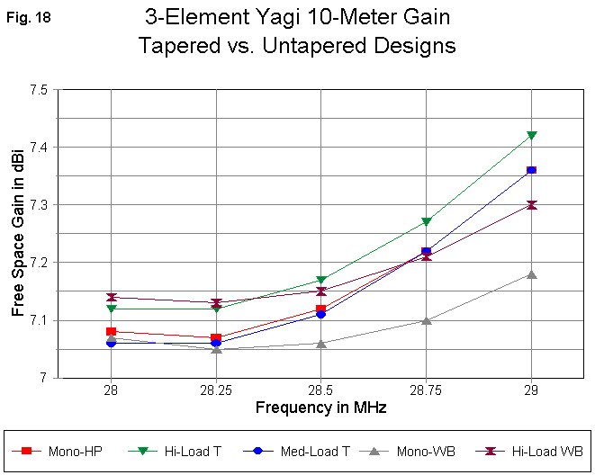
Fig. 18 provides gain curves from 28 to 29 MHz for all 5 Yagis in the tables above. The gain values for the high-performance, short boom models are within a few hundredths of a dB of each other. The difference between the tapered and untapered wide-band Yagis averages under 0.1 dB.
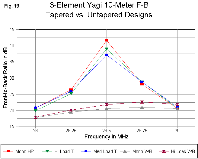
The front-to-back curves in Fig. 19 tell a very similar story. All three of the high-performance, short boom Yagis show the same high mid-band peak in 180-degree front-to-back ratio, with similar pass band edge performance. The wide-band models show insignificant differences and also end up at very similar values at the wider band edges of the design. In short, with some care in adjusting element lengths--and occasionally the element spacing-- one can achieve the same basic performance from a tapered-diameter Yagi as from a uniform-diameter version of the same design.
Some 15-Meter Designs
In Fig. 20, we can examine the differences between high-load and medium- load element tapers for 15 meters.
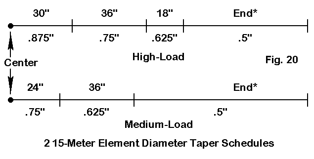
Obviously, each level requires an additional, larger tubing segment to accommodate the longer element. Corresponding design dimensions for the original uniform-tape design and tapered-diameter designs appear in the following table.
Antenna        Uniform-Dia (0.75")      High Load      Medium Load
Dimension
Refl. Length        284.4               289.0          286.0
Refl.-DE Space       48.4                48.0           48.0
DE Length           260.5               274.0          271.0
DE-Dir. Space        72.6                92.0           92.0
Dir. Length         248.5               254.0          251.0
The difference in overall boom length is immediately noticeable--a matter of 19" or over 10% of the total length. In some respects, the tapered- element beams are not the same design as the study model, although the longer elements required by element-diameter tapering are apparent. The 15-meter study model was scaled directly from the 10-meter model, while the taper-diameter models came from work by K6STI.
One consequence of the longer boom with about the same reflector-driven element spacing is a lower feedpoint impedance. The following table shows the difference:
Antenna        Uniform-Dia (0.75") High Load           Medium Load
Frequency
21.0           27.4 - j  6.2       20.5 - j  9.2       21.4 - j  9.9
21.225         26.6 - j  0.0       20.4 + j  1.0       22.1 + j  0.3
21.45          23.5 + j  9.0       20.7 + j 10.0       22.5 + j  9.4
The shorter, uniform-diameter model would permit more versatility in matching and would likely be amenable even to a 35-Ohm 1/4 wl matching section. The lower impedances of the longer tapered-diameter models would likely require a beta match or similar, with suitable adjustments to the length of the driven element.
However, there may be compensation for the lower source impedance.
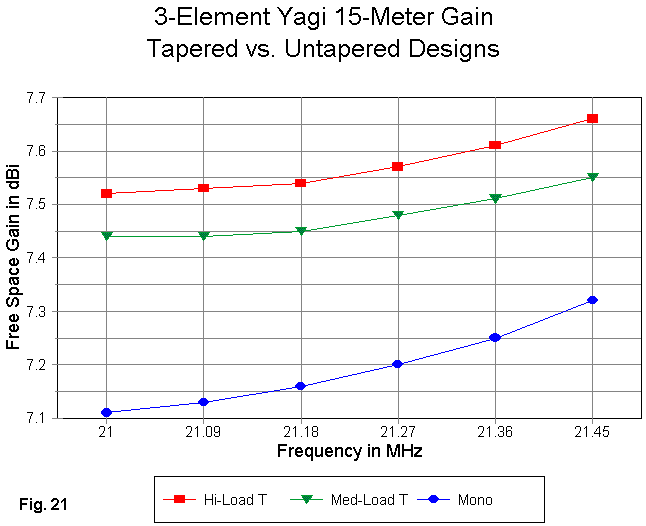
The gain curves in Fig. 21 show the nearly half dB gain advantage accrued from using a longer boom. Not only is the gain higher, but it changes less across the 15-meter band.
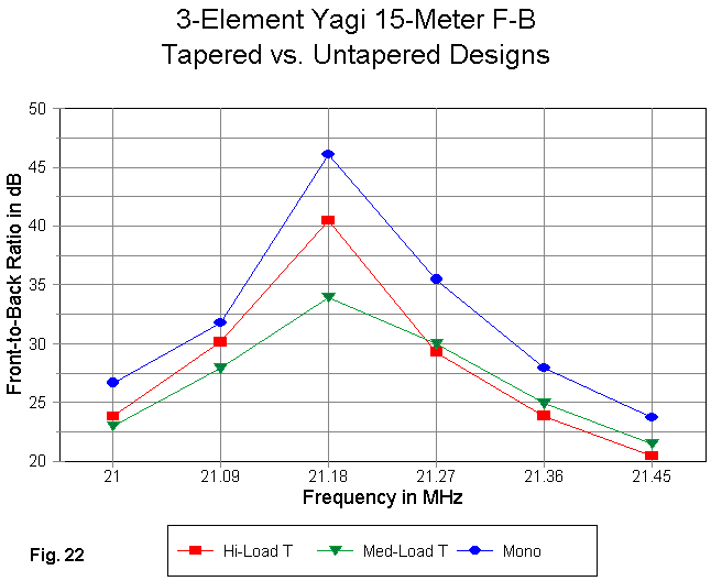
In Fig. 22, we discover that all three models have excellent front-to-back ratios, never worse than 20 dB. Since the peak value reflects a deep dimple in the rearward lobes, differences have less importance: roughly equally high marks go to all three designs.
In the end, the decision comes down to whether the lower feedpoint impedance and the 19" of additional boom are worth the added gain. The shorter length boom with tapered elements can be developed into a beam having characteristics very close to the study model--as we saw in the case of 10-meter beams.
Some 20-Meter Designs
Tapered element design can become quite complex as we move to the 20-meter band. See Fig. 23.
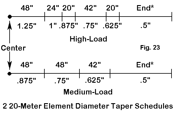
The medium load element adds one more section to the corresponding 15-meter element. However, the high-load model adds two sections. In addition, the 1/4" jump in diameter as we enter the center section of the element generally suggests that two tubing sections of the same length are used: a 1.125" diameter section inside the 1.25" section.
Once more, if we turn to our short-boom model, we obtain dimensions of the following values.
Antenna        Uniform-Dia (1.0")       High Load      Medium Load
Dimension
Refl. Length        425.9               447.3          438.0
Refl.-DE Space       72.4                80.0           90.0
DE Length           389.6               421.6          414.0
DE-Dir. Space       108.6               106.0          106.0
Dir. Length         371.7               393.3          386.0
Despite the use of larger diameter sections in each element, the high-load element has the more radical taper and results in a greater required element length at each position than the thinner but less radically tapered medium-load element. The element position adjustments, necessary to sustain performance across the 20-meter band, elevate the source impedance from about 25 Ohms to about 30 Ohms.
A similar significant lengthening occurs with the long-boom (24') high performance Yagi design.
Antenna        Uniform-Dia (1.0")       High Load
Dimension
Refl. Length        414.7               433.8
Refl.-DE Space      125.5               125.5
DE Length           396.0               415.0
DE-Dir. Space       145.1               145.1
Dir. Length         372.6               391.0
Note that the boom length is here preserved. The average element length increase is about 19" for the radically tapered high-load element or nearly 5% of the total element length.
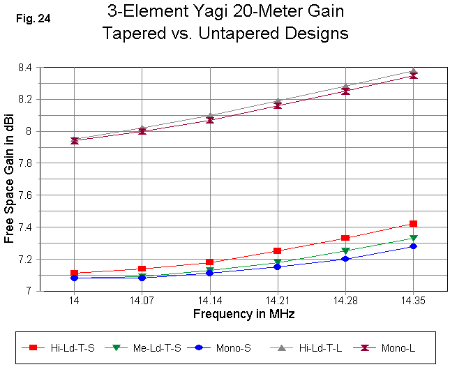
The gain curves in Fig. 24 show that for each type of beam, we obtain similar gain curves relative to untapered and tapered models.
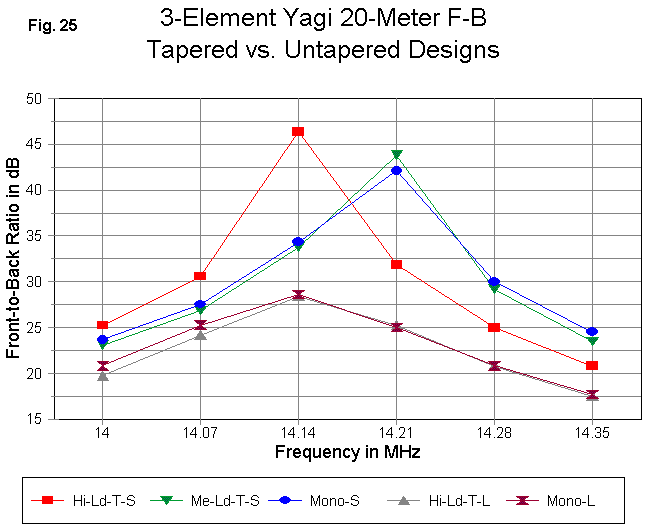
In Fig. 25, we can see the front-to-back performance. The two high- performance models have values that closely overlap. The short-boom models place their front-to-back peaks at different frequencies. If the high-load model peak were moved upward in frequency by just a bit, its band-edge performance would closely parallel the other two models.
Some Miscellany
The point of our exercises has been to familiarize you with the effects of element-diameter tapering on overall Yagi dimensions. Moving from a uniform-diameter design to one that includes multiple tubing sizes requires careful redesign to take into account the actual element-diameter taper used. This is no casual design process, but rather a task of optimizing dimensions throughout the design. Programs such as YO and YagiMax can mechanize the process to a great degree.
The particular models used in this exercise do not mean that any particular design is recommended. However, the range of models does suggest a set of standards, relative to performance expectations and boom length.
Several items have not be covered. For example, the models surveyed so far all assume insulated mounting relative to the boom. We have not looked at the so-called "plumber's delight" element mounting system. One technique for dealing with the effects of direct electrical mounting to the boom is to create a short, large-diameter wire at the very center of the element.
Also missing is a consideration of the requirements and the hazards of long booms. When viewed from the mast-to-boom mounting assembly, the boom is a pair of lever arms. The longer the arm, the greater force exerted by an element of some preset size. Seemingly small increases in boom length can require close attention to boom strength. The increase in boom length can also create larger wind forces as viewed from mast. Nonetheless, very durable assemblies have been created for Yagis far larger then our 3-element models.
Although the high number of variables involved in the physical structure of 3-element Yagis would make a short discussion less than useful, there is a subject to which we might devote one more part in this series: feeding and matching the antenna to a standard 50-Ohm coaxial cable feedline.
Updated 07-31-99. © L. B. Cebik, W4RNL. This item appeared in AntenneX, June, 1999. Data may be used for personal purposes, but may not be reproduced for publication in print or any other medium without permission of the author.