 Part II: The Input Story

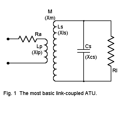
The input resistance in series with LP is designated RA and is the resistive impedance coupled back to the primary. As we have noted, the secondary tuned circuit at resonance has no series-equivalent reactance and therefore does not couple a reactance back to the primary or input side of the circuit. To couple a compensating capacitive reactance back to the primary, one must resonate the secondary at a frequency somewhat higher than the operating frequency. In this case, there is both a resistive and reactive component to the secondary impedance, and hence, resistive and reactive components to the impedance coupled back to the primary.
Since the offset adjustment has little effect on the value of the coupled resistive component, but chiefly provides the capacitive reactance needed to cancel the inductive reactance of the primary inductor, we shall normally not mention (except where necessary) this offset adjustment. However, tuner designers and users should remember that this offset is a normal part of most antenna tuner adjustments. When we use an SWR meter between the ATU and the transmitter, we are making this adjustment automatically in seeking a 1:1 SWR. If we leave the reactance of the primary inductor uncompensated, the SWR will be above 1:1 for the case where RA is 50 ohms.

In editions of the ARRL Antenna Book since at least 1960, a different equation is given, presenting the initial appearance that the account there may differ from this one. However, let's do a little work on equation (1) above.
First, we know that the coefficient of coupling (k) and the mutual inductance (M) are related by the square root of the product of the two coupled inductances. Since converting an inductance to its reactance at any given frequency is a matter of multiply the inductance by 2pif, which cancel out in the relationship, we can also express how k relates to M this way:

Squaring both sides of equation (2), we can replace the term XM2 in equation (1), cancel out an XLS above and below the line, and reach this step:

For a parallel loaded circuit where the load resistance is small compared to the resistive impedance of the resonant circuit, the loaded circuit Q is approximately the following:

Equations (3) and (5) give us important information about the design of inductively coupled ATUs. First, the resonant secondary ATU is most efficient when the numerical values of RA and XLP are the same. (Note that we only approximate this condition when we detune the secondary in order to cancel the reactance in the primary.) Under these conditions, a relationship emerges between k and Q:

The upshot is this: we can optimize our ATU design by varying the relationship between the load resistance and the reactance of the secondary inductor, or we can optimize our design by varying the coefficient of coupling--or we can do both. That gives us a good bit of flexibility in designing the ATU.
We shall look at both sides of the circuit for ways to optimize our design. As we did in Part I, we shall stick to purely resistive loads and leave the question of reactance on the line for later consideration. Likewise, we shall retain the parallel configuration of the secondary circuit and devote some attention later on to low impedance loads and the series-counterpart of the circuit. Let's master one thing at a time.
With the chosen values and an assumed k of 0.6, the mutual reactance was 100 ohms. The secondary loaded Q was 2.8 or so (which tells us that everything we are doing here is an approximation, since the equations are truly accurate only for Qs above 10). Whichever equation we use to obtain the coupled resistance to the primary, we obtain about 54 ohms. However, this value of RA applies only to a load of 1500 ohms resistive.
What happens if we have a different load to match with the same components? The following table tells us a story.
                      Some Values of RA for Various Loads
                  RL (ohms)            Loaded Q       RA (ohms)
                   500              0.95         18
                  1000              1.89         36
                  1500              2.84         54
                  2000              3.79         72
                  2500              4.73         90

Table 1.  Some values of RA for various loads (RL) in the standardized circuit.
In order to effect a 50-ohms match, we might consider altering the value of XLP. This would entail altering the size of the primary inductor, which would inevitably alter the values of M and k. However, assuming we could retain a k of 0.6, the following table gives us the trend of value changes needed for the 50-ohms match.
                    Some Values of XLP for a 50-ohms Match
                  RL (ohms)            Loaded Q       XLP (ohms)
                   500              0.95         146
                  1000              1.89          73
                  1500              2.84          53
                  2000              3.79          37
                  2500              4.73          29

Table 2  Some values of XLP for various loads (RL) to achieve a 50-ohms match.
For most inductively coupled tuners, this is not a practical alternative. The primary inductor is normally fixed within or immediately over the secondary inductor. Tapping it precisely would require closely spaced taps. Mechanically, the switch leads or the manual tapping wires would introduce variations in the impedance seen at the input terminals of the tuner. But the exercise does give us a feel for what happens at the primary with changes in antenna feedline loads.

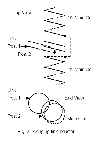
The swinging or movable link or primary inductor, moving within a space at the center of the secondary coil, effectively changes the coefficient of coupling and hence the mutual impedance of the coupled inductors. The value of k increases as coupling is increased, that is, as the link is moved into the secondary field. Notice that the value of k changes continuously with changes in the primary inductor position, in effect giving us a variable k-control. We cannot say in the abstract what the value of k might be with each possible position. However, we can look at the values of k necessary to effect a 50-ohms match in our standard circuit.
                     Some Values of k for a 50-ohms Match
                  RL (ohms)            Loaded Q         k
                   500              0.95         0.99
                  1000              1.89         0.71
                  1500              2.84         0.57
                  2000              3.79         0.50
                  2500              4.73         0.45

Table 3  Some values of k for various loads (RL) to achieve a 50-ohms match.
Since values of above about 0.6 are normally not achievable with air-wound inductors, the standardized 7 MHz tuner circuit would not be able to match loads less than about 1500 ohms. However, we might select a larger primary inductor value, which would reduce the required values of k. Unfortunately, this move would also increase the value of XLP so that it no longer match the desired value of RA, thus setting a less than optimum ratio between the two figures.
A second alternative results from equation (6), which suggests that we might redesign the coupler secondary, tailoring its Q to provide a more usable range of values for k. We shall retain a target values for RA and XLP of 50 ohms each. Let's also set a limit: at a load impedance (RL) of 300 ohms, the value of the coefficient of coupling (k) will be 0.6. From Table 3, we can see that at lower impedance values, k will need to reach values not likely to be achieved, but at load values above this value, required values of k will be lower. By swinging the link further out from the main inductor, these values of k can be achieved.
Since k, XLS, and RL are related, we can rewrite equation (6) as

               Some Alternative Values of k for a 50-ohms Match
                  RL (ohms)            Loaded Q         k
                   500               4.63        0.46
                  1000               9.26        0.32
                  1500              13.89        0.27
                  2000              18.52        0.23
                  2500              23.15        0.21

Table 4  Some values of k for various loads (RL) to achieve a 50-ohms match
with the revised swinging link coupler.
Although this redesign achieves the immediate goal of providing values of k within the range of a swinging link for a span of realistic load values, all is not well. When the Q exceeds a value of about 10, the tuning becomes very sharp, requiring one to reset the tuner variables more than once across a single amateur band.
Although the swinging link might be combined with some techniques applied to the tuner secondary that we shall explore a bit further on, they are no longer the input circuit of choice. Swinging links were once popular, but have essentially gone out of style because they are mechanically large and complex. Moreover, there is a much simpler means of achieving the same goal.
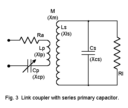
The most common way to adjust the input circuit of an inductively coupled ATU is with a series capacitor. See Figure 3 for a revision of our standard circuit to incorporate the unit.

The first task that the new series capacitor, CP, can perform is to cancel the reactance of LP. This frees us from having to retune the secondary circuit to achieve this effect. Essentially, CP and LP form a resonant series circuit, leaving only RA as the input impedance of the overall impedance matching circuit.
We choose the value of CP to resonate with LP at the lowest frequency in the band to be covered. In our running example, at 7 MHz the reactance XLP is 53 ohms; hence, the reactance of the capacitor must be the same at resonance. The corresponding capacitance is 430 pF. However, we show the capacitor as a variable for a set of good reasons.
The values just calculated apply for the case where the overall circuit load is 1500 ohms resistive. However, not all loads faced by the ATU will be exactly 1500 ohms. Other load values will not be converted by the circuit constants to the values of RA and XA in the example (where XA has had a value of zero).
In the first episode, we showed how to cancel the value of XLP by tuning the secondary circuit to a higher frequency, so that at the operating frequency, XLP and XCP did not have the same values at the operating frequency. As we increased the frequency at which XLP and XCP were equal, a value of XA was coupled back into the primary circuit, and the value was capacitive. At the same time, the value of RA slowly lowered.
Had we begun with a secondary load, RL, that was higher than 1500 ohms, the value of RA would also have been initially higher. To a limited degree, we may use the same technique of making XLP and XCP equal at a higher frequency to produce something closer to 50 ohms for RA. However, when we do this, we also couple a capacitive reactance, XA, into the primary circuit. Since this coupled reactance provides part of the reactance needed to cancel the reactance of the primary inductor, the new series capacitor, CP, must now be set at a lower reactance--just enough lower so that the sum of its reactance and the coupled reactance together cancel the coil reactance. A lower reactance in CP means a higher capacitance. Therefore, the series capacitor used in the primary should have a value sufficiently greater than the target value to handle such cases.
Lower values of RL would have yielded lower values of RA. To raise them, within limits, we may set XLP and XCP to be equal at a frequency below the operating frequency. This will simultaneously raise the value of RA coupled back to the primary and also introduce a value of inductive reactance XA. The series capacitor must now be set at a higher value of reactance (and a lower value of capacitance) to cancel the sum of the introduced and the primary inductor reactances.
The series capacitor in the ATU primary circuit may be thought of as a "fine tuning" device, capable of allowing a given fixed secondary circuit inductor and its associated variable capacitor to handle a wider range of loads without directly altering the coefficient of coupling. Still, the range of variation that the primary capacitor, CP, can handle is limited. For wide ranges of RL, other means of coupling the load to the primary are necessary. The chief function of the series primary capacitor is always to cancel the primary inductor reactance, thus presenting the input source with a resistive load.

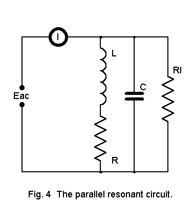
Figure 4 shows a conventional parallel tuned circuit. Note that the series resistance in the coil leg (RS) is in addition to the load resistance (RL), but the two are not in either direct series or parallel with each other. When the operating Q of the circuit is above 10, the presence of RS makes little or no difference to the notion of resonance. When the operating Q is below 10, differences begin to appear.
When a series or parallel tuned circuit is just off resonance, we expect several differences from performance at resonance. First, XL is not equal to XC. Second, the current through the parallel circuit (in contrast to current within the circuit load) is greater than minimum. Third, the current through the circuit is not in phase with the voltage. In a high loaded-Q circuit, XL and XC are equal, current though the circuit is minimum, and current is in phase with the voltage all at just about the same frequency. However, in low-QL circuits, these three phenomena occur at somewhat different frequencies.
The goal in tuning a parallel resonant circuit in an impedance matching circuit is to achieve minimum current within the parallel circuit and maximum current to the load at the operating frequency. With respect to this goal, successful tuning of the circuit produces resonance. It is not the goal to have the current and voltage in perfect phase within the tank circuit or to have XL and XC be equal. These latter phenomena may occur at nearby frequencies, and they become resonant frequencies relative to each phenomenon. (In 1995, the ARRL Handbook expanded the coverage of low-Q parallel resonant circuits to cover these points more thoroughly: see pages 6.37-6.42 of any edition since then.)
Hence, for the aims of the inductively coupled tuner, the definition of resonance that is relevant is to maximize current in the load of the secondary (equivalent to minimizing current through the paralleled inductor and capacitor). Hence, when we retune the secondary to achieve maximum power output from the tuner, we are resonating the circuit, no matter what values of XL and XC may be required to do this.
We have also ignored the values of resistance and reactance coupled from the primary into the secondary. Given the disparity of coil sizes, the amounts are quite small in most matching situations and hardly call for any change of control settings to maximize current in the secondary. However, the effect is real and the control settings are not quite the same as they would be without the mutual coupling. In some cases, these further adjustment requirements add to those just mentioned; in other cases, they may partially cancel each other out. Nonetheless, the overall readjustment of the tank circuit to account of all factors affecting maximum current flow within the tank circuit are part of the effort to achieve resonance.
The most certain way to assure that proper resonance has been achieved is some form of output power measurement.
We have only begun to see the flexibility of the inductively coupled impedance matching
circuit by surveying the most common variations we impose on the input side of the circuit. In
the next installment, we shall look at some useful variations of the output side of the circuit.
Updated 11-28-97. © L. B. Cebik, W4RNL. Data may be used for
personal purposes, but may not be reproduced for publication in print or
any other medium without permission of the author.