 2. From Place to Laplace
Although the equations for conversion are common handbook material, let's repeat them here for reference (in case you have a calculator handy):

where Xl is in ohms, L is in Henries, and F is in Herz. Incidentally, NEC works almost exclusively in basic units for inductance and capacitance, so using the most basic equations is apt.

where Xc is in ohms, C is in Farads, and F is in Herz.
Now we may turn to a definite example. We shall resurrect the 1/2-size #14 copper wire dipole in free space, with its 2 mid-element loads. For the moment, we shall let the resistance be zero and worry only about the load reactance, which was 870.4 ohms.
Using the appropriate equation, we discover that this reactance, at the target frequency of 14.15 MHz, yields a required inductance of 9.79 microH. However, for modeling purposes, we should get used to specifying this and similar inductances in the computer form of engineering notation, hence 9.79e-06 H. (Likewise, although most HF capacitance values are in pF, for example, 23 pF, we need also to express them in a similar way, that is, as 23e-12 F. Notice that we insert no spaces in any part of the number.)
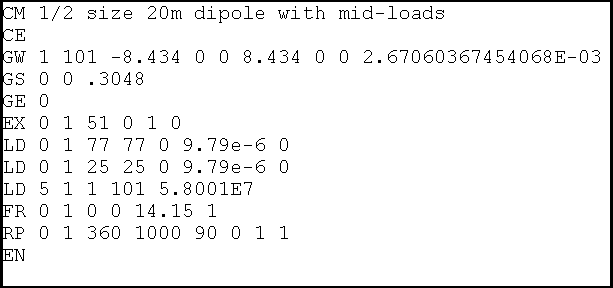
The following figure shows the antenna description in NEC input file format for the 20-meter dipole with the loads expressed in type 0 format:

Each of the load lines (ignoring the type 5 wire loading) follows the conventions just noted:
  LD  0    1     77       77       0       9.79e-6       0
  LD  0    1     25       25       0       9.79e-6       0
     Type Tag 1st-Seg Last-Seg Resistance Inductance Capacitance
For type 0 loads, some of the entries have changed their meanings, specifically, the entries after resistance. Note that the order in which we enter the loads makes no difference to the calculation, although--except for examples like this one--I tend to enter all loads in some logical order. That practice makes modification easier, since I can more easily find the load I wish to modify and less easily select the wrong one. following the order of the elements in the antenna and working from left to right or from End 1 to End 2 for each element generally works in most cases.
The inductance entry is in the notation we described. In some cases, exponents with leading zeroes will be truncated to a single digit; in others, the leading zero will appear. Where values are missing (we had no resistance and no capacitance in this example, enter zero. NEC knows to treat these as missing values, whether we are dealing with series or parallel loading circuits. NEC does not create inappropriate short circuits for missing values. The user has to do that by specifying very small values other than zero.
Besides allowing the user to enter a load line in the antenna description, NEC-Win Pro provides two other means for entering load data. One is the load screen accessed from the load line.

On this screen, we specified a Series RLC load and entered zeroes for the missing values and the inductance value. This screen produces the entry line for the load at segment 77.
Within the NEC-Win Basic model, calling up the drag-and-drop screen produces the following screens:

Although the data is the same, this screen set permits us to specify the load position as a percentage of element wire length.
Within EZNEC, entering R-L-C loads is a 3-screen sequence, as shown in the following partial replication of EZNEC screens.

Since EZNEC defaults to R+/-jX values, we changed the load type. If we had been working from a previous model that had R+/-jX loads, these loads would have been deleted. Therefore, we had to enter two new loads in the exact positions occupied by the old loads, as seen on Screen 1.
We begin the process of providing values for these loads on Screen 2, by selecting either a series or parallel type load.
On screen 3, we enter the values for the R, L, and C components of the load, using the engineering-computer notation, as shown.
Once we enter the values, they appear at the bottom of the screen as Laplace coefficients for the equations in the program that supply the NEC core with its input data. I have treated this example as if I were modifying existing values. Had there been no previous entry, all numerator (Num) values would have been 0.000E+00. However, note that the inductance value appears as the numerator for S^1.
For simple series loads, the Laplace coefficient for resistance will appear as the numerator for S^0 and the inductance will appear as the numerator for S^1. In some complex loads, some of the coefficients will not be the same as the values entered. Therefore, it is a good practice to keep a record of the actual R, L, and C values entered for each model.
Now that we have our model, we might as well run it. EZNEC Pro, using NEC- 4 returned a gain of 1.76 dBi and a source impedance of 26.08 + j1.65 ohms. NEC-Win Pro, running NEC-2 return values of 1.76 dBi and 26.09 + j2.13 ohms. In short, no difference.
     Load 1:   S^0            S^1            S^2
     Num       0.000E+00      9.790E-06      0.000E+00
     Den       1.000E+00      0.000E+00      0.000E+00
If we add an arbitrary 2 ohms resistance in series with the inductor, we see the following table:
     Load 1:   S^0            S^1            S^2
     Num       2.000E+00      9.790E-06      0.000E+00
     Den       1.000E+00      0.000E+00      0.000E+00
For inductors and resistors in series, we now know where to look for the values we inserted.
With capacitive loads, the table takes on a different look. Consider once more our slightly long dipole that we center loaded with a capacitor having a reactance of -j102.8 ohms. If we convert the reactance to a capacitance at 14.15 MHz, the value required is 109.4 pF or 109.4e-12 F. If we now plug this value into the EZNEC load screen, we see a table like this one:
     Load 1:   S^0            S^1            S^2
     Num       1.000E+00      0.000E+00      0.000E+00
     Den       0.000E+00      1.094E-10      0.000E+00
The capacitive value shows itself in the denominator line at S^1. Complex loads having resistance and capacitance are a bit more complex in appearance. Let us place an arbitrary 2 ohm resistor in series with the capacitor. The coefficients now look like this:
     Load 1:   S^0            S^1            S^2
     Num       2.000E+00      2.188E-10      0.000E+00
     Den       0.000E+00      1.094E-10      0.000E+00
The resistance is in the numerator line at S^0, while the capacitance value remains where it was. The new number in the numerator line at S^1 is the product of the two values. Incidentally, note that all values are transformed to the form x.xxx, with whatever exponent is needed to make the figure equal to the number entered.
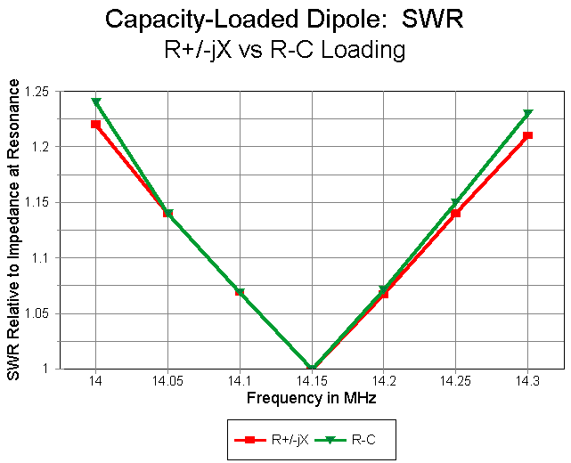
The long dipole with capacitive loading is also interesting because it seems (and only seems) to suggest that it makes little difference whether we use a complex R +/- jX or an R-L-C load when evaluating an antenna across a ham band. A frequency sweep of the capacitively loaded dipole from 14.0 to 14.3 MHz produces the following table of source impedance values for each type of load:
     Frequency      Load=R+/-jX         Load=R-L-C
                    Source Impedance    Source Impedance
     14.00          86.88-j17.46 ohms   86.87-j18.58 ohms
     14.05          87.90-j11.64        87.90-j12.37
     14.10          88.94-j 5.85        88.94-j 6.23
     14.15          90.00+j 0.05        90.00+j 0.04
     14.20          91.05+j 5.78        91.05+j 6.13
     14.25          92.13+j11.70        92.13+j12.42
     14.30          93.22+j17.48        93.22+j18.55

The SWR curves are hardly distinguishable, as one might expect from the table of source impedance values. However notice the steeper rise in reactance with the series R-L-C load, which provides the correct reactance of the loading capacitor for each frequency checked.
When the characteristics of an antenna vary more extremely across a band of frequencies, the trend becomes more noticeable and important. Consider our short, mid-element-loaded dipole once more. Just as an example, we shall use the model that does not introduce the series resistance that represent losses due to having a finite Q. The table below provides the source impedance values reported by each type of load, while the graph supplies comparable SWR data.
     Frequency      Load=R+/-jX         Load=R-L-C
                    Source Impedance    Source Impedance
     14.00          25.13-j25.45 ohms   24.84-j42.26 ohms
     14.05          25.44-j16.46        25.24-j27.82
     14.10          25.76-j 7.44        25.66-j13.14
     14.15          26.08+j 1.65        26.08+j 1.65
     14.20          26.41+j10.62        26.52+j16.47
     14.25          26.74+j19.93        26.96+j31.77
     14.30          27.08+j29.07        27.42+j47.06

Clearly, the R+/-jX loaded model provides an excessively optimistic report of the antenna operating bandwidth--by nearly a factor of 2. Once more, just to be repetitive, accurate modeling of a loaded antenna across a band of frequencies requires the use of R-L-C loads.

where Rs and Xs are the series values of resistance and reactance and Rp and Xp are the corresponding parallel values of resistance and reactance.
For parallel to series conversions:

with the same designations.
Parallel R-L or R-C circuits do not have much utility, since they are only the converted counterparts of series R-L and R-C circuits. However, for the exercise, you can convert the mid-element loads with a Q of 300 into their parallel counterparts, arriving at values of Rp=261243 and Xp=870.41 ohms from the series values of Rs=2.9 and Xs=870.4 ohms. The reactance, of course, yields a required inductance of 9.79e-6 H
For NEC-Win Pro, we would simply select a parallel RLC circuit and enter the calculated values of R and L, with zero for the missing C. In EZNEC, we would similarly select a parallel RLC load and enter "261243,9.79e-6,0." In the coefficients table, we would see
     Load 1:   S^0            S^1            S^2
     Num       0.000E+00      2.558E+00      0.000E+00
     Den       2.612E+05      9.790E-06      0.000E+00
We recognize the values of R and L in the S^0 and S^1 positions of the denominator line, while the value in the S^1 position of the numerator is simply the product of the two.
To further establish the equivalence of appropriately converted series and parallel loads, here are sample results for the mid-element loaded short dipole run with both types of loads in NEC-4 within EZNEC Pro:
Frequency           Series RLC Model              Parallel RLC Model
             Gain (dBi)  Source R+/-jX     Gain (dBi)  Source R+/-jX
14.00 MHz      0.92      30.07-j42.36        0.94      29.96-j42.38
14.15          0.93      31.55+j 1.52        0.93      31.55+j 1.52
14.30          0.94      33.13+j46.95        0.92      33.26+j46.95
The most useful application of parallel loads is with traps and similar RLC circuits. A trap is a resonant L-C circuit used to provide multiband service from a single element. There are several studies devoted to traps listed in the main index to these articles. Here we shall only cover certain essentials related to traps as computer modeling loads.

The figure shows a typical dual-band trap dipole for 20 and 10 meters, resonant on 28.5 and 14.175 MHz. The element material is 0.5" diameter aluminum. The traps are resonant on 27.75 MHz to equalize performance on the two bands.
The models for this consist of three wires. The first is 6.41' (76.9" or 1.95 m) long with 12 segments. The last wire is identical to the first. Between them is a wire 16.36' (196.3" or 4.99 m) long, with 31 segments. The first and last segments are loaded by parallel R-L-C circuits representing the traps.
The figure also shows trap circuit-equivalents. The upper schematic provides the basis for modeling a trap. The main losses in a trap are normally in the coil, given its finite Q. For this model, a Q of 200 was selected as being slightly more conservative than some commercial traps available. However, Qs from 100-400 have been successfully constructed.
The trap values are 1.2 microH and 27.4 pf to achieve resonance at 27.75 MHz. The reactance of each component is about 210 ohms at resonance. With a Q of 200, the coil series resistance is about 1.05 ohms. To create a true parallel circuit, we must convert the series inductive leg to its parallel equivalent. The inductance remains almost identical to its series value, but the equivalent parallel resistor becomes quite large.
However, we must do the conversions at other than the trap resonant frequency. At 28.5 MHz, the net reactance of the circuit is capacitive, and the required parallel resistance is nearly 43 kohms. At 14.175 MHz, the net reactance is inductive and the required parallel resistance is about 21.3 kohms. There is a program within HAMCALC and also within another trap article in this collection that will perform the requisite calculations, as well as explain the procedure in detail.
In effect, we have two sets of parallel R-L-C loads, one for 10 meters, on for 20 meters. (The amount that the parallel resistance changes within a band the size of 20 meters is too small to be significant, especially in view of the rounded figures used in most cases for coil Q, although one may calculate the resistor's value for each frequency of interest.)
Entering the parallel R-L-C circuit for which ever band interests us is done in the same way as for series loads, except that we select the parallel option and enter figures for all three types of components. The following figure shows a typical NEC-Win Pro entry screen for one of the loads for the 10-meter model.

With EZNEC, entry procedures are also the same as with a series load. The Laplace coefficients lines that result may seem mysterious at first sight:
     Load 1:   S^0            S^1            S^2
     Num       0.000E+00      5.155E-02      0.000E+00
     Den       4.296E+04      1.200E-06      1.413E-12
S^0 in the denominator line is the resistance, while S^1 in the same line is the inductance. S^1 in the numerator line is the product of the two numbers. It would appear that S^2 in the denominator line must have something to do with the capacitance, but the value seems to have no relationship to the 27.4 pF entered. However, if we divide S^2(d) by S^1(n), we arrive at our original capacitance. This is handy to keep in mind if you forget to record the capacitance you entered.
At 28.5 MHz, the model (in NEC-4) returns a gain of 2.08 dBi, with a source impedance of 85.69 + j0.02 ohms. The same model using NEC-2 returns the same gain and a source impedance of 85.57 - j0.33 ohms, establishing equal reliability in both programs for handling parallel R-L-C loads. At 14.175 MHz, the model with the appropriate parallel resistor yields a gain of 1.97 dBi with a source impedance of 63.16 - j0.63 ohms. (Once more, these figures are excessively precise for practice, but are given to illustrate the numbers provided by the programs.)
As with all loads, the parallel R-L-C load is placed in series with sources and transmission lines. There is no direct provision for placing a load in parallel with sources or transmission lines within NEC.
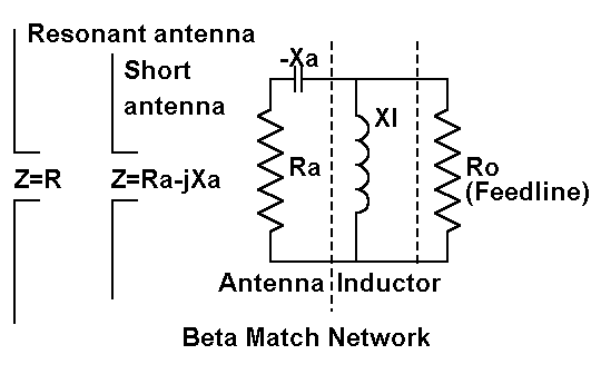
The beta match is a modified L-network for transforming a higher (feedline) impedance to a lower (antenna) impedance. An L-network consists, when transforming to a lower impedance, of a shunt or parallel reactance on the high impedance side and a series reactance of the opposite type on the low impedance side.

As the figure shows, the modification consists in letting the antenna feedpoint impedance supply the series reactance and then installing only the shunt reactance. Normally, we make the antenna a bit shorter than resonant to provide a capacitive series reactance and then add a shunt inductive reactance. The inductive reactance may be in the form of an inductor or a shorted transmission line length (the hairpin). However, for special cases, we might also make the antenna long, providing a series inductive reactance and then install a shunt capacitive reactance.
Beta values are easily calculated, either from the following equations or from a program such as found in the HAMCALC collection. Let's sample the normal case, letting the series reactance be capacitive and the shunt reactance be inductive.
The common factor in L-networks is delta, which may be called the working Q or measure of efficiency of the network.

From delta, we can calculate the requisite values of Xa (the series reactance at the antenna feedpoint) and Xl (the shunt inductor).

Now let's return to one of the antennas in the first episode of this series. Consider the half-length 20-meter dipole with mid-element loading. This model used a single wire of 101 segments 16.868' long. The mid- element loads were on segments 25 and 77 and had values of 870.4 ohms. The source impedance of this antenna was 26.08 + j1.65 ohms.
The transformation from 26 ohms to 50 ohms for coax feed is a good job for the beta match. Using the equations above, we find a delta of about 0.95, resulting in an Xa of 24.97 and an Xl of 52.7. Now, let's model this antenna, working toward the beta match.

The figure indicates several steps we need to take in order to ensure an adequate model of the antenna and its beta match. Step 1 we have already taken in modeling the original antenna. The gain, using lossless mid- element loads in this exercise, is 1.76 dBi.
Step 2 consist of preparing the model for a parallel load. Break the single antenna wire into 3 parts, the two outer parts having 50 segments each, with the loads installed where they physically had been in the original model. This would place them on segment 25 (49%) of the left wire and segment 26 (51%) of the right. At the center is a single segment wire the length of the segment that it replaced (about 2" in this example). When we run this model, we obtain a feedpoint impedance of 26.08 +j1.68 ohms and a gain of 1.76 dBi, establishing that we have not made anything but a cosmetic change in the model.
Step 3 will establish the antenna shortening in order to provide the desired series source capacitive reactance. Here, we have two choices. We may physically shorten the outer wires, or we may simply reduce the mid- element loads a bit. Let's do the latter. Lowering the mid-element load reactances to 857 ohms each produces a feedpoint impedance of 25.63 - j23.20 ohms.
Step 4 requires that we add to the physical structure of the antenna. We add 3 1-segment wires to form a box around the center source wire. On the wire parallel to the source wire, we initially install a resistive load of 10 Mohms. This resistive load produces what is essentially an open circuit in the new structure so that we may check the effects, if any, of the structure on the antenna performance. Under these conditions, we obtain a feedpoint impedance of 25.97 -j23.55 ohms, and an antenna gain of 1.70 dBi.
Although these changes are small, they do indicate that the structure is not insignificant. Had we used fewer segments, each would have been longer, and the box wires would have had greater effects on performance of the model. Reversing the positions of the source and the resistive load provide another indication that the structure is not insignificant: the feedpoint impedance and the gain change by very noticeable amounts. In practice, we tend to ignore small lumps and bumps in linear antenna element structure, but careful modeling suggests that their cumulative effects on performance may be more than trivial.
Step 5 consists in replacing the resistive load with the reactive load indicated by our work with the equations. Placing a purely inductive reactance of 52.7 at the parallel load point yields a source impedance of 53.28 - j0.10 ohms. Using a very small structure to model the parallel load produced results very close to predictions from the equations.
Step 6 takes into account the Q of the beta coil. Let us assume a small inductor with a Q of 300 and hence a series resistance of 0.18 ohms. This small move produces a source impedance of 53.13 + j0.12 ohms, all the while making no change in the antenna gain of 1.70 dBi in free space.
If we wish to check the performance of the beta matched antenna away from the design frequency (14.15 MHz), we must make one further move: change the load type from a Type 4 (R +/- jX) load to a type 0 (series R-L-C) load. The resistance remains at 0.18 ohm, while the requisite inductance is 0.59 microH. At the target frequency, the source impedance is reported by NEC as 52.91 + 0.13 ohms.
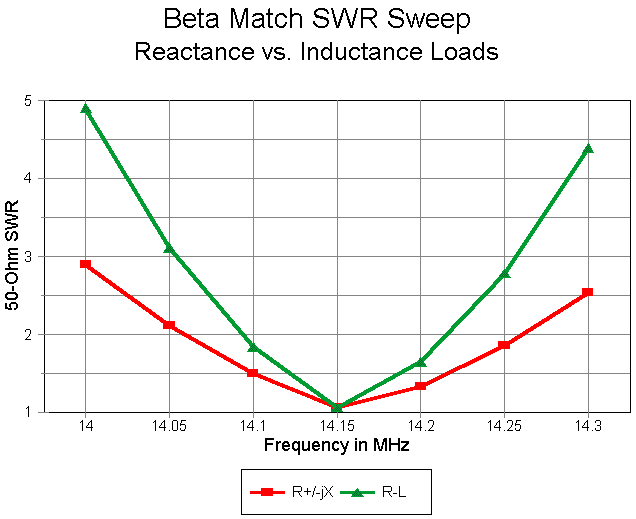
The importance changing to a series R-L-C load becomes apparent the moment we frequency sweep the completed antenna model from 14.0 to 14.3 MHz.

As the graph shows, assuming that the reactance of the coil will remain "close enough" to the value at the design frequency produces an overly optimistic curve of SWR. Using a series R-L-C load for which NEC provides the correct reactance at each frequency checked shows a much narrower (and more correct) operating bandwidth for the antenna. The difference is more than slight.
As the exercise demonstrates, it is possible to model loads in parallel to
a source using the smallest feasible structures and paying close attention
to details along the way. Among those details are deviations from the
modeled performance without the added structure and an evaluation of the
degree to which those deviations also apply to the real-world antenna.
Equally important is using the right load type to model antenna performance
across the relevant band of frequencies.
Updated 12-28-97. © L. B. Cebik, W4RNL. Data may be used for
personal purposes, but may not be reproduced for publication in print or
any other medium without permission of the author.