
 A 10-Meter LPDA
Here is an EZNEC description of Eric's design:
3 el. Log Cell (S=0.12, K=1.1)     Frequency = 28.8  MHz.
Wire Loss: Aluminum -- Resistivity = 4E-08 ohm-m, Rel. Perm. = 1
              --------------- WIRES ---------------
Wire Conn.---End 1 (x,y,z : in)  Conn.---End 2 (x,y,z : in)   Dia(in) Segs
1         0.000,-84.400,  0.000         0.000, 84.400,  0.000 3.75E-01  27
2       -47.700,-94.300,  0.000       -47.700, 94.300,  0.000 3.75E-01  31
3       -105.25,-105.25,  0.000       -105.25,105.250,  0.000 3.75E-01  35
               -------------- SOURCES --------------
Source    Wire      Wire #/Pct From End 1    Ampl.(V, A)  Phase(Deg.)  Type
          Seg.     Actual      (Specified)
1          14     1 / 50.00   (  1 / 50.00)      1.000       0.000       I
No loads specified
                -------- TRANSMISSION LINES ---------
Line  Wire #/% From End 1   Wire #/% From End 1    Length    Z0   Vel Rev/
      Actual  (Specified)   Actual  (Specified)             Ohms Fact Norm
1    1/50.0  (  1/50.0)    2/50.0  (  2/50.0)  Actual dist   50.0  0.95  R
2    2/50.0  (  2/50.0)    3/50.0  (  3/50.0)  Actual dist   50.0  0.95  R
3    3/50.0  (  3/50.0)  Short ckt (Short ck)    5.000 in   200.0  0.95
4    1/50.0  (  1/50.0)  Short ckt (Short ck)   14.000 in   200.0  0.95
Ground type is Free Space
Eric used 3/8" diameter elements with a 50-Ohm, VF-0.95 antenna transmission line. (The function of the 0.95 VF is largely to be conservative for construction methods using pairs of wires, bars, or booms with periodic spacers.) TL #3 is a shorted stub at the rear of the antenna, while TL #4 is a beta match shorted transmission line stub. The natural source impedance of the antenna is in the 20s, with a considerable capacitive reactance, and the beta match becomes a natural form of matching to a 50-Ohm line.
The one feature about Eric's design that troubled me was its extra 9.4" of boom length. Everything else in this exercise had been designed for 8' booms (that might be obtained from hardware depots rather than special sources, since the ultimate goal is a garage-built antenna). Hence, I wondered what the consequences might be of shortening the boom. To provide some initial element length and spacing numbers to compare with Eric's, I resorted to LPCAD once more. LPCAD is intentionally limited to 4 elements as the minimum number for any design. So I simply increased the upper frequency limit so that the third element fell at about the 8' mark, and deleted the shorted element when transferring the model to EZNEC. Only a little adjustment was necessary to derive a 3-element monoband LPDA on an 8' boom.
lpda10m                  Frequency = 28-30  MHz.
Wire Loss: Aluminum -- Resistivity = 4E-08 ohm-m, Rel. Perm. = 1
              --------------- WIRES ---------------
Wire Conn.---End 1 (x,y,z : in)  Conn.---End 2 (x,y,z : in)   Dia(in) Segs
1         0.000,-106.00,  0.000         0.000,106.000,  0.000 3.75E-01  43
2        50.559,-95.400,  0.000        50.559, 95.400,  0.000 3.75E-01  41
3        95.339,-86.000,  0.000        95.339, 86.000,  0.000 3.75E-01  39
              -------------- SOURCES --------------
Source    Wire      Wire #/Pct From End 1    Ampl.(V, A)  Phase(Deg.)  Type
          Seg.     Actual      (Specified)
1          20     3 / 50.00   (  3 / 50.00)      1.000       0.000       I
No loads specified
                -------- TRANSMISSION LINES ---------
Line  Wire #/% From End 1   Wire #/% From End 1    Length     Z0   Vel Rev/
      Actual  (Specified)   Actual  (Specified)              Ohms Fact Norm
1    1/50.0  (  1/50.0)    2/50.0  (  2/50.0)  Actual dist   50.0  1.00  R
2    2/50.0  (  2/50.0)    3/50.0  (  3/50.0)  Actual dist   50.0  1.00  R
3    1/50.0  (  1/50.0)  Short ckt (Short ck)   19.000 in    50.0  1.00
4    3/50.0  (  3/50.0)  Short ckt (Short ck)   15.000 in   200.0  1.00
Ground type is Free Space
In this final design using 3/8" elements, I used a 50-Ohm line for the antenna transmission line stub, along with a VF of 1.0. Stubs can be adjusted in length for the materials used during construction, so long as the inductive reactance is the same.
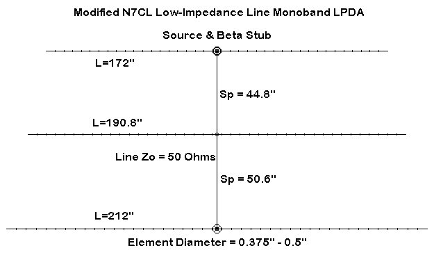
The sketch may place some perspective on the numbers in the tables.
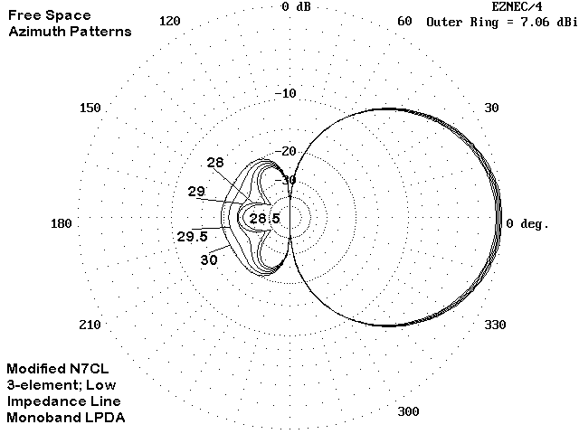
The overlaid patterns of the modified N7CL LPDA--using a version with 0.5" elements and a VF of 0.95, show a generally promising pattern across 10 meters, with only the 30 MHz front-to-back value falling below 20 dB. How this model stacks up against Eric's original will emerge later on in this phase of the design process.
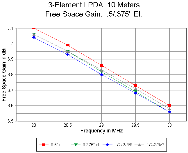
The antenna free space gain across 10 meters shows a decreasing set of values from above 7 dBi to about 6.6 dBi. The half-inch model is marginally superior, but the constant 3/8" element version is never worse than the mixed size models. Hence, from the perspective of gain, changing element size to achieve a constant length-to-diameter ratio is an exercise in futility.
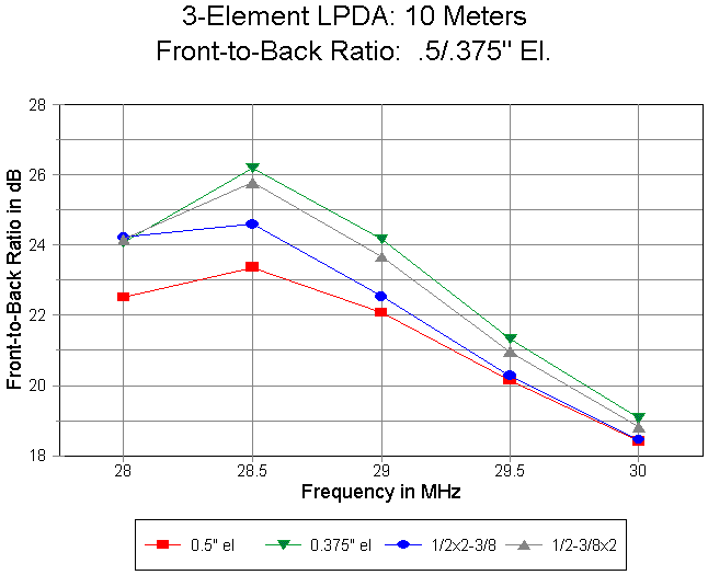
The front-to-back curves tell essentially the same tale. The constant element diameter curves bracket the mixed-size models. Interestingly, a pattern picked up earlier replicates itself here: the higher the gain, as yielded by a fatter element, the lower the front-to-back ratio for any given set of element lengths and spacings on a given frequency. Here the thinner (3/8") element passes through 20 dB at about 29.7 MHz, while the larger (0.5") element drops to about 18.5 dB at 30 MHz.
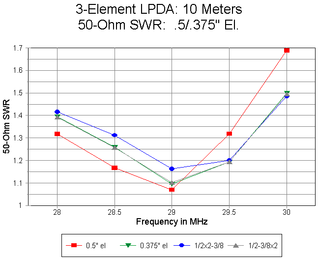
For the type of design in question, the SWR increases more rapidly above the design center frequency than below it. Using 2 or 3 3/8" elements provides the shallowest curve, while using 2 or 3 1/2" elements provides steeper curves on one or the other end of the band of operation.
Although a successful version of the short-boom 3-element LPDA might well be built using half-inch or 3/8-inch elements, the thinner elements actually provide a modicum of advantage over the thicker ones. In no category did the tapered element diameter schedule provide any advantage over using elements of one diameter throughout the design.
The descending gain pattern is a function of the design using an inductive stub to close the rear of the antenna transmission line and to tailor the antenna operating characteristics. Removing the stub from the rear provides an antenna with more gain on every frequency, but far less front- to-back ratio. One way to view the stub is as a load that electrically lengthen elements acting as a reflector. This view is at best partial, since every element is active at every frequency in the narrow span of a monoband LPDA. However, like reflector loads in parasitical beams, the increased front-to-back ratio also has the consequence of reducing gain by a small amount and of changing the source impedance. What Eric did in his design was to balance these effects to yield a 3-element LPDA having the characteristics he wanted. These characteristics are general enough to carry over into modified versions of his work.
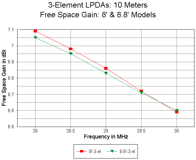
A comparative gain curve for the N7CL original and the shortened version shows excellent coincidence. In fact, in the shorter version, other characteristics were sacrificed to provide as high an upper band limit gain as possible, since the shorter model tended toward a more rapid gain drop off in its original set of dimensions.
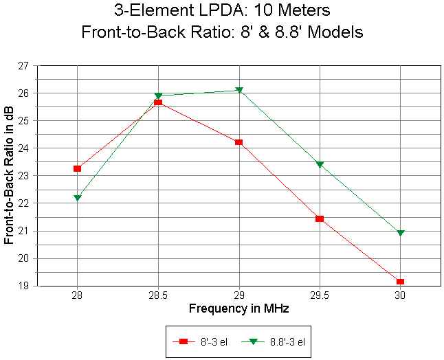
As noted, squeezing gain from a monoband LPDA tends to lower the front-to- back ratio in the area of squeeze. Although the front-to-back curve for the 8' boom model might have its curve moved slightly to equalize low-end of the band values, it would still show a deficit relative to the 8.8' boom model at the upper end of the band. In short, for the monoband LPDA, gain and front-to-back ratio are trade-offs. When there is a surplus, as in 4- element models, the trade-off appears mostly as a minor adjustment of the operating characteristic curves. When the values are at the limits of a preset specification sheet, the trade-off process become serious.
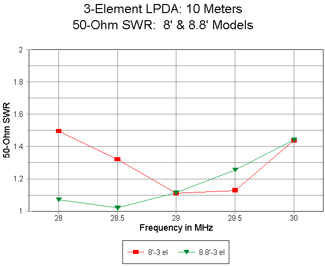
What was traded to achieve as shallow as possible as gain curve with acceptable front-to-back ratio was source reactance. The unmatched variance in reactance across the band for the 8' boom model is much greater than for the 8.8' model. The result when beta matched for 50-Ohms is a flatter SWR curve for the 8.8' boom model than for the 8' boom model. Both versions of the monoband LPDA maintain an SWR of less than 1.5:1 across the band, but the long boom model is clearly superior.
For the average builder, using the long boom will result in slightly superior overall performance. As well, it will likely be somewhat more forgiving of the normal range of variances that occur using home shop construction methods. However, the exercise in modifying the design has revealed something of the limits of the 3-element design and the trade-offs necessary to achieve a design close to the specifications set up at the beginning of the project.
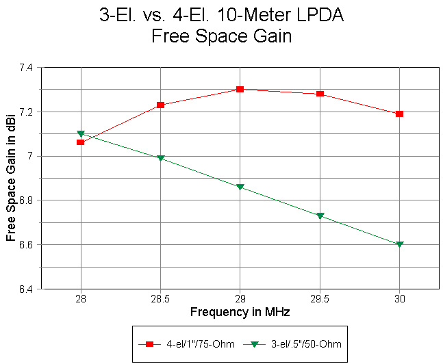
The gain curve of the 4-element design is clearly superior to that of the 3-element design. For designs so far investigated, it appears that a 3- element LPDA cannot sustain a gain near 7 dB over all of the 2 MHz bandwidth. At the upper end of the band, the 3-element design shows about 0.6 dB less gain than its 4-element counterpart. Moreover, the 3-element design begins to fall short of the desired goal of having 3-element 8' boom Yagi gain all across the band. (Remember that one of the specifications set was not merely that the antenna achieve a match across the 10-meter band, but that it also sustain certain operating characteristic levels throughout.)
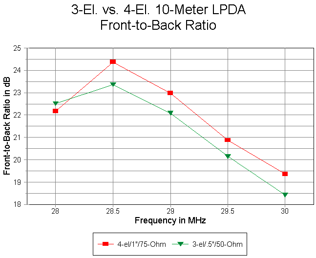
Although the 4-element front-to-back curve is superior to that of the 3- element LPDA, the difference is not so great as to be decisive--at least not to the degree that the gain curve differentials appear to be decisive. Although the upper band edge front-to-back for the 3-element model drops below 20 dB, the amount is operationally slight.
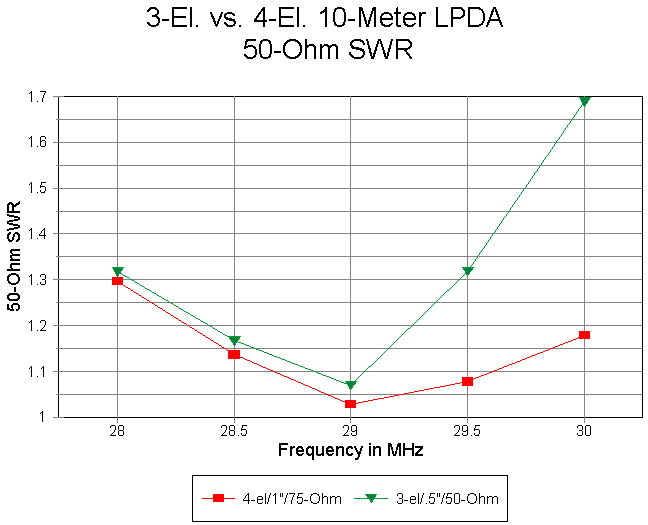
The SWR curve for the half-inch 3-element model using a 0.95 VF line is steeper than some of the others for more perfected models of the smaller antenna. However, in this context, it demonstrates somewhat vividly the SWR curve advantage of the 4-element model using fat elements. Although the small antenna SWR curve cannot be considered unacceptable, the 4-element model curve is especially attractive for rigs having ultra-sensitive power-reduction circuits. (Note that the original N7CL design has an SWR curve more closely akin to the 4-element design.)
To conclude that the 4-element design is superior to the 3-element design on the same length of boom (or slightly longer) is not to classify the lighter antenna as unacceptable. If the reduced upper band-end gain is acceptable and the marginalness of the front-to-back ratio in the same region is not obstacle, then the simpler design might well be the design of choice.
Although seldom used for ordinary transmission line purposes, flat-face conductors can be brought to much closer center-to-center distances than round conductors. In addition, they present a higher equivalent "diameter" than round conductors in this application.
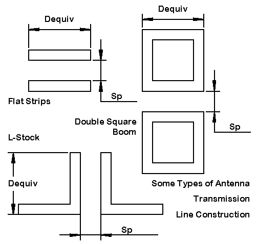
The sketch shows some possibilities for the construction of low impedance antenna transmission lines for the monoband LPDA. Flat plates might present the most problems for home constructors without welding equipment for making connections. Jerry Hall, K1TD, used a modification of the L- stock configuration with his 2-meter LPDA. Square stock promises the possibility of combining both boom and transmission line functions in one assembly.
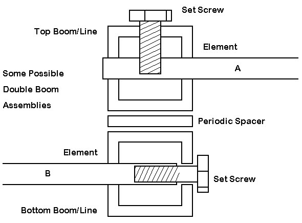
Perhaps the chief problem facing the user of square stock is the element attachment problem. The figure shows two types of element locking mechanism. However, what is not shown can create more mechanical problems than what is shown (since elements can be tapped). First, the element is suspended from a very small region at its end. Either the square stock should be thick or it should be reinforced so that the element does not rest on a metal edge. The holes in the element should be as precise as possible. For the "top" set crew model, inserting a length of stiffening rod or tubing inside the main element may also distribute the load.
The elements are non-symmetrical relative to each boom and tend to place twisting forces on the boom pieces. In the sketch, there is compression on the right side and separation on the left. Hence, near each element, the booms should be locked, possibly using an insulating plate with screws into each boom piece. The plates should be attached on both side of the boom assembly to counter both the compression and separation forces. Such plates might well eliminate the need for periodic spacers to maintain boom spacing.
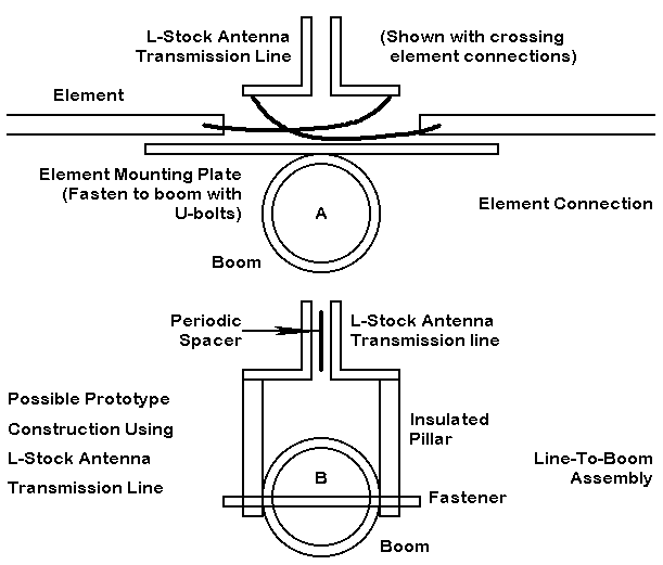
L-stock requires a separate boom, as well a some system for keeping the antenna transmission line parts far enough away from the boom to negate any interaction. The spacing is convenient, since it also provides enough room for crossing wires (for at least one element in the 3-element designs and 2 in the 4-element designs). The L-stock flanges are convenient for making attachments to the connecting wires without disturbing the facing surfaces of the transmission line. If the orientation shown in the sketch yields problematic interactions with the boom, the co-planar parts of the stock can be moved to the top edge. Of course, the element mounting plates must be insulators.
For initial prototypes, something like the L-stock version of the antenna transmission line seems advisable. Revisions to the design that emerge during or after initial construction may leave some holes in the flange, but these will likely not affect the performance or mechanical soundness of the antenna. The open structure permits many test-bed practices that might well be revised in final versions. For example, the spacers might be held in place with cable tie-wraps until testing and final positioning has been set. Likewise, simple copper wire might be used as the connecting wires to the element, even if the final version might call for aluminum strips to minimize bi-metal effects.
These preliminary thoughts on constructing a prototype suggest that I am getting closer to actually committing to one--at least one to try out. I have reduced the materials needs to those I can obtain locally for the most part--or obtain easily from ham vendors. Some of the mechanical parts may require some ingenuity, remembering that this is a garage project and not a manufacturing prototype. So I am expecting a good bit of trial and error, as well a setting some dimensions (like the antenna transmission line spacing) through both pre-element and post-element assembly testing.
Now if I could only decide whether the 3-element version is good enough or
whether I should try the 4-element version for more assured performance
across the band. My thanks to Eric Gustafson, N7CL, for sharing his
design, even if it has resulted in a bad case of indecision.
Updated 11-14-98. © L. B. Cebik, W4RNL. Data may be used for
personal purposes, but may not be reproduced for publication in print or
any other medium without permission of the author.