 Some Model Quads:
A persistent question about multi-band quads, whether 2-element models or larger, is the proper way to feed them. There are several questions associated with this basic inquiry, but only a few have I been able so far to shed any light on through the models in my collection. But perhaps it is worth a note or two on the question to reveal how far I have gotten so far.
The strongest interactions in 2-element multi-band quads appear to be these: 20 vs. 10 meters when 10-meters is active; 12 vs. 10 meters when 10 meters is active.
I have modeled 2-band combinations of 12 and 10 meter quads. I am not satisfied with the results, even though the source position distorts the driver shape the least. Finding dimensions that will yield good free space patterns and usable feedpoints on both bands is not easy. The 12-meter driver acts like a 10-meter reflector, but one that either surrounds the 10-meter driver or is ahead of it. The 10-meter reflector acts like a 12- meter director, in conflict with the 12-meter reflector. although I have been able to stabilize 12-meter performance in models, 10-meters still eludes me.
I have also modeled common-feed 20-10-meter combinations. Here, the problem appears to differ. The 10- and 20-meter drivers interact when 10 is driven, because the 20 meter driver is about 2 wl long and has a low impedance--something like 200 Ohms, when the 20 meter quad is driven away from the presence of the 10-meter elements. The combination on 10 meters not only shows angular side bulges, in line with the pattern of a 2 wl loop, but as well is sensitive to the loop distortions created by the common feed position between the two drivers. In free space, the patterns tilt downward by a considerable degree.
In a five-band common-feed quad, I have found no satisfactory arrangement that will yield patterns and impedances good on all bands. So far, when the patterns look reasonably clean (meaning that they are similar to the patterns of monoband quads), the impedances become unworkable, and vice versa.
These notes do not mean that there is no satisfactory arrangement. That is why I have shown no figures here. The net result simply means that I have found no such arrangement, if it exists. However, my criteria are fairly stringent. For an arrangement to be satisfactory, the quad must on all bands have a satisfactory pattern and a satisfactory source impedance. There is some latitude in the impedances that might be acceptable, but the patterns must approach the standards set by quad models using separate feed points for each band. So far, I must admit failure in this quest.

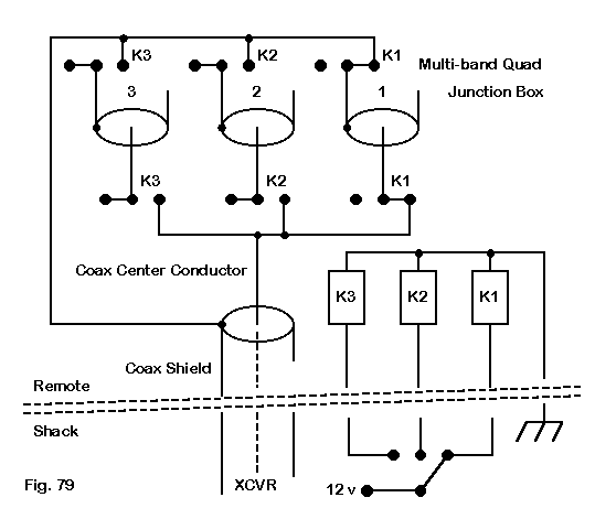
Key to this system is that the unused lines are completely open. Neither their braid nor their center conductors are connected to anything, including the box or each other. Each line, by standard design, is 1/4 wl long at the operating frequency of the unused driver. Depending upon the placement of the remote switch, one may need to use either 0.66 or 0.78 VF feedline to get the closest approximation of the right length (without coming up short).
The benefit of this system is that all relays are enclosed in a single box that can be effectively weather proofed (while allowing drainage or evaporation of condensation). Whether this system has disadvantages, we shall examine shortly.
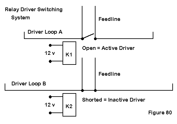
A second system is to short the feedpoint of each driven loop right at the feedpoint itself, as illustrated in Fig. 80.

In this system, a weatherproofed relay is positioned at the feedpoint. The relays can be "normally closed" types so that the loops are shorted without power to the system. The only energized relay is located at the active driven element. It is opened, thus allowing the feedline to be in series with the element loop.
This system assures that the unused driver loops are closed--a condition generally considered to be more optimal for achieving good quad patterns and usable source impedances. However, the weight and exposure of the relays when placed at the sources makes this system somewhat more of a mechanical design problem than the single remote box and 1/4 wl stubs. It entails in most designs the use of a separate feedline for each band--or a secondary switching system for the feedline.
As a consequence of this complexity, the most common design for separately feeding each band of a multi-band quad has been the central switching box and 1/4 wl stubs. However, there are still a few questions which we might pose about this system:
1. Do we need the stubs to be open-ended to create a short across the loop?
2. Since the stubs will be 1/4 wl long at the frequency for which the driver is tuned, will they effectively short the loop when the quad is operated at other frequencies?
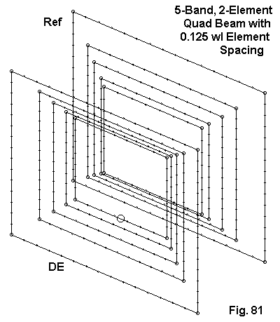
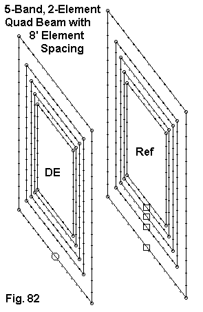
To look into these questions together, I remodeled a couple of 2-element multi-band quads that we looked at in Part 4 of this series. One was the study quad that used a constant 0.125 wl spacing between elements. This is a version of the spider-type quad in which elements for lower bands are both ahead and behind elements for higher bands. The second was the KC6T design that uses an 8' boom for all bands, along with capacitive reflector loading. Although 2 models might not be exhaustive as a study, the pair may give us some suggestive results.

The data I collected from this model comes in 4 parts, three of which I shall present in tabular form. First is the performance data for the model with the unused driver loops closed. The data includes the Free Space gain in dBi, the 180-degree front-to-back ratio in dB, and the source impedance in Ohms.
Frequency      Gain      Front-to-Back       Source Impedance
 in MHz        in dBi    Ratio in dB         (R +/- jX Ohms)
28.5           7.48      20.28               40.0 - j 0.3
24.94          7.32      25.83               41.5 + j 0.1
21.225         7.16      24.70               52.9 + j 0.2
18.118         7.23      32.38               60.9 - j 0.5
14.175         7.23      28.92               84.2 - j 0.1
We may consider this our base-line data against which we may compare data from modeling variations.
The first variation was to connect a 1/4 wl line to each driver. The other end of the line of the active driver element was brought to a very short wire used as the remote source point. For this exercise, the TL facility of NEC-4 was used, so the lines are handled as mathematical lines, not as physical lines that may play a desired or undesired role in far field pattern formation. Two subvariations were used. In one, each unused line was set as an open line, which uses a very remote wire and a specified very high impedance (or very low admittance) to create the open circuit. The second subvariation used a remote short, thin wire that serves as the source wire when the element is active. Inactive lines are simply connected to their unique wires without a source. The results between the two systems varied only in the hundredths column of the model output reports, and so only one set of data will be given.
For reference, the line lengths used are as follows, where the Frequency column indicates the driver element to which a given transmission line stub is connected.
Frequency      Stub Length    Stub Length
 Band           in feet        in inches
10              8.628         103.54
12              9.859         118.31
15             11.585         139.02
17             13.717         164.60
20             17.347         208.16
In each case, the source impedance of the element when driven was used as the line characteristic impedance (rather than using some common figure, such as 75 Ohms). The lines use a VF of 1.0, since line loss variations cannot be determined by NEC. Actual lines would be shortened in accord with the actual velocity factor of the line used.
With the unused lines either brought to their individual short wires or left open, the following performance figures were reported by NEC-4.
Frequency      Gain      Front-to-Back       Source Impedance
 in MHz        in dBi    Ratio in dB         (R +/- jX Ohms)
28.5           7.43      20.10               39.2 + j 0.0
24.94          7.33      25.64               41.0 - j 0.0
21.225         7.17      25.02               51.6 - j 0.1
18.118         7.23      32.12               60.0 + j 0.7
14.175         7.23      28.85               85.6 - j 0.1
To the degree that NEC can model the situation, the use of 1/4 wl lines-- each set to the operating frequency of the driver--that are open at the remote switch point creates virtually no change in the patterns or the source impedances of the 2-element multi-band quad on any band. for this model, at least, it does not matter that the lines are not 1/4 wl long at the frequency of current operation. They provide sufficient closure to allow standard performance on each band.
The second variation set each unused driver line (without any other change to the line) at a remote short circuit. In principle, this would open the unused driver loops. The results reported by NEC-4 are the following.
Frequency      Gain      Front-to-Back       Source Impedance
 in MHz        in dBi    Ratio in dB         (R +/- jX Ohms)
28.5           7.33      19.68               54.9 + j16.9
24.94          7.17      28.95               71.0 + j 3.7
21.225         7.07      23.02               79.0 + j 1.1
18.118         7.20      37.31               78.6 - j 0.7
14.175         7.23      29.57               88.6 + j 0.7
The use of shorted 1/4 wl stubs for this concentric quad model is certainly not catastrophic. There is a slight gain loss with increasing frequency, while the changes in the front-to-back ratio are variable. These mixed results tend to indicate only a small shift in resonant frequency for the driven loops as a result of the inactive loops having shorted stubs.
The more noticeable affect is the increase in source impedance for the quad at higher frequencies relative to the impedance with shorted unused loops (or open stubs). Note that this source impedance is the value at the end of the stub for the active band, using a characteristic impedance line equal to the source impedance of the baseline value from the first table. nonetheless, this technique bears watching in other models, since it seems at first appearance a useful result.

For this quad, the baseline data is as follows.
Frequency      Gain      Front-to-Back       Source Impedance
 in MHz        in dBi    Ratio in dB         (R +/- jX Ohms)
28.5           7.46      22.81               75.4 - j 0.3
24.94          7.20      30.63               76.9 + j 0.3
21.225         7.28      34.40               69.5 + j 1.7
18.118         7.30      31.71               69.5 + j 1.7
14.175         7.21      24.01               76.6 + j 1.6
As notes in Part 4, one of the interesting aspects of this design is the relatively constant source impedance from band to band. This factor simplifies the stub modeling. The line lengths will be the same as in the first test, but the characteristic impedances will be between 70 and 75 Ohms. For the two subvariations of an open-circuit remote stub end, the results are as follows.
Frequency      Gain      Front-to-Back       Source Impedance
 in MHz        in dBi    Ratio in dB         (R +/- jX Ohms)
28.5           7.42      22.54               71.7 + j 0.2
24.94          7.18      31.60               74.0 + j 0.7
21.225         7.28      35.20               68.2 - j 1.2
18.118         7.30      31.72               69.0 - j 1.3
14.175         7.21      23.97               77.0 - j 1.7
As with the concentric quad model, the flat-plane model shows no significant difference in any performance parameter between the baseline data set and the open unused stub set.
The only test remaining is the one in which the unused driver stubs are short circuited at their remote ends. The data for this test is as follows.
Frequency      Gain      Front-to-Back       Source Impedance
 in MHz        in dBi    Ratio in dB         (R +/- jX Ohms)
28.5           -1.34     14.74                 4.7 + j83.0
24.94          6.63      28.14                41.7 - j96.5
21.225         7.13      30.02               183.2 - j23.8
18.118         7.26      34.61               120.7 - j12.5
14.175         7.22      24.36                80.8 - j 1.1
The flat-plane model obviously suffers far more from the use of shorted stubs for the unused driver than does the concentric model. 12 and 10 meter operation suffers the most and requires considerable redesign before even approaching the performance in the baseline data set.
What is more assured, although by no means finalized, is the fact that unused driver loop closure is desirable for attaining good performance on all bands of a 2-element, 5-band quad. With relatively equal assurance, we can also suggest that cutting the open-ended stubs to 1/4 wl at the loop's normal operating frequency suffices to allow the array to achieve peak performance on all bands (within, of course, the design limitations inherent in each type of quad). Modeling does not seem to turn up any particular problems with the open-stub system of remote switching.
This study is very incomplete, being limited to a subset of models in my collection. Nevertheless, the results seemed worth adding to this series, since they do appear to allay any hesitation over using the open-stub remote switching system and to suggest that using shorted stubs may be unwise--or at least not fully predictable for any given situation.
Updated 4-2-99. © L. B. Cebik, W4RNL. Data may be used for personal
purposes, but may not be reproduced for publication in print or any other medium
without permission of the author.