
As a result of a number of requests that I have received for models of quads from my files, I thought that I might make a batch available all at once. Actually, I shall divide the material into 3 sections: full-size 2- element quads, shrunken 2-element quads, and multi-band quads of 2 or more elements. My collection lacks some interesting types, such as a good model of the Swiss quad.
I shall not be adding modeling files per se, but I shall add some model descriptions that one can transcribe into any modeling software format. Not many descriptions are necessary, because virtually all models are constructed in the same manner. Initially, all models begin in a free space environment. Each loop is centered on a 0, 0 X (or Y) and Z axis. The loop corners are then defined.
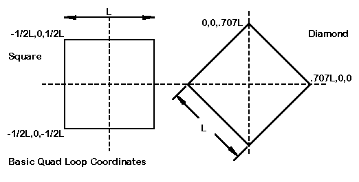
For square loops with bottom wires parallel to the ground, a coordinate set consists of two entries, each one-half the side dimension, with + or - signs as dictated by the particular corner of the loop. Hence, the upper left corner of a loop with 9' sides will use -4.5, 0, 4.5 as X, Y, and Z coordinates.

Diamond loops require that one multiply one-half the length of a side by 1.414 to arrive at the peak, which will then be at either the X (or Y) or the Z coordinate when the other is zero. The same loop as above, but turn to a diamond configuration, would use for the top coordinates 0, 0, 6.36.
The "unused" coordinate, of course, receives the spacing dimension between elements. Simple monoband quads can set any element to zero and count from that point. Multi-band spider-hub quads often use a zero-center point to best advantage. Once one has one element complete and correct, ne may then use an appropriate copy mechanism to replicate the element, changing coordinate numbers (or letters, if symbolic entry is used) to account for dimensional differences.
Once the loops have been constructed in a free space environment, adjustment for height above ground is a simple matter of changing all Z-coordinates by the same amount. Of course, the amount will be the height above ground if the height represents the loop center. Other adjustments may be needed if the height represents the bottom of the lowest wire.
Despite a few remnant protestations from a few quad designers, antenna modeling programs have proven very effective and accurate for designing and analyzing quads. All programs have some limitations, so let's note the most important ones.
MININEC 3.13, the core of such programs as ELNEC, AO, and NEC4WIN, has a problem with corner-clipping as segment centers tend to give the effect of linking and ignoring the small increment to the actual corner junction or pulse. The standard method for reducing this effect to negligible amounts is length tapering. Length tapering can be manually or automatically implemented, and the automatic systems can be visible or invisible to the user who does not look at the post-run wire tables for the antenna. It is a process of reducing the length of segments gradually as corners are approached so that two conditions are met. First, the segments closest to the corner are very short without exceeding the minimum segment length, either absolutely or relative to wire diameter. Second, the changes in length from one segment to the next are within the boundaries set for accurate output from the core.
NEC (-2 or -4) (as found in programs like NECWires, EZNEC, and NEC-Win) does not require length-tapering at corners, since the currents are taken from the entire segment. However, NEC has two limitations to note. First, angular junctions of wires having different diameters yield inaccurate results. This is no problem for the standard wire quad loop. However, some quad design use large diameter tubular horizontal members and vertical wires to connect them. NEC has a problem with this configuration. Second, NEC requires that the source be placed on a segment, which presents problems to corner feed points, such as might occur on a diamond shaped quad. We shall look at the alternatives for handling this situation as we proceed through the models.
The initial monoband quads will all be for 10 meters. In most instances, I shall not express dimensions in terms of equations of the order "L = 1234/f" since the required length of a quad loop will vary with the wire diameter on any band. The fatter the wire, the larger the quad loop for the same resonant frequency. Therefore, unless one adjust the wire size as well as the length, scaling will be imperfect. Since the models will use #14 AWG copper wire (0.064" diameter"), direct diameter scaling makes for unlikely assemblies (for example, #10 AWG on 20 meters based on the use of #14 AWG on 10 meters).
With these reservations in mind, we may look not only at the models, but at their characteristics as well. The exercise will provide some useful expectations of various kinds of quads (but by no means all kinds), including recognition of what may be misleading about showing only peak data without the remainder of the data curves across a band of intended operation. We shall also find some easy ways out of a few seeming blockades to achieving desired performance curves. In the last part, we shall take up the question of remotely switching stubs as a feed system for multi-band quads.
The following books should be required reading for anyone interested in large or small quads:
William Orr, W6SAI, and Stuart Cowan, W2LX. Cubical Quad Antennas, 3rd Ed. Lakewood, NJ: Radio Amateur Callbook, 1993
Bob Haviland, W4MB. The Quad Antenna. Hicksville, NY: CQ Communications, 1993
John Koszeghy, K2OB. High Performance Cubical Quad Antennas, 2nd Ed.
Updated 4-2-99, 2-25-2000. © L. B. Cebik, W4RNL. Data may be used for personal
purposes, but may not be reproduced for publication in print or any other medium
without permission of the author.