MODELING AND UNDERSTANDING SMALL BEAMS
PART 3: THE EDZ FAMILY OF ANTENNAS
The Extended Double Zepp (EDZ) has been a lonely antenna for most of its life, since Hugo Romander, W2NB, introduced its potential to the amateur community in 1938. Even its vertical cousin, the Extended Single Zepp, seems to have changed its name to the 5/8-wavelength ground plane to avoid identification with the EDZ.1 By contrast, everyone knows about the family of antennas related to the half-wavelength dipole: the quarter-wavelength ground plane, the 2-, 3-, and more-element Yagis, the ZL-Special. The EDZ also spawns a family of antennas that include parasitic and phase-fed beams. This report tries to fill in some of the family tree without necessarily recommending everything that the computer modeling says is theoretically possible with the EDZ. What looks good on the computer may not work out in backyard practice. However, the ideas we shall consider may spur someone else to realize some of the potential shown by EDZ beams.
Here is a sample: A good 2-element dipole-based Yagi shows about 3 1/2 dB gain over a similarly placed wire dipole. To achieve 6 dB gain over that same piece of wire requires 4 to 5 elements. Suppose one could make an 2-element antenna with the same 6 dB gain over the original wire. That fact would qualify the EDZ beam as a small beam in boom length, although not in element length. Both parasitic and "135-degree" phase-fed versions of the EDZ promise the computer to give the indicated performance. However, achieving that performance will impose severe restrictions that mark the antennas for special purposes under narrowly defined circumstances.
For this study, all antennas are referenced to 10-meters, with any exceptions clearly noted. Within limits, the results can be scaled, at least within the upper HF region of the spectrum.
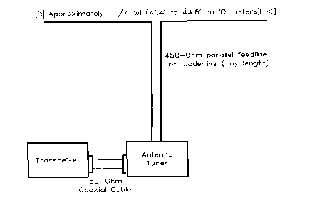
Before turning to the more distant cousins of the EDZ, let's begin at home with the basic horizontal EDZ. It is a wire antenna, about 1 1/4 wavelengths long, fed in the center. It presents a high, complex impedance at the feedpoint, ordinarily necessitating the use of parallel feeders and an antenna tuner. Fig. 1 suggests the basic set-up.
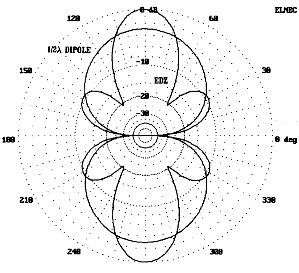
The chief advantage of the EDZ over a resonant half-wavelength dipole is bidirectional gain. See Fig. 2, which provides patterns for free space half-wavelength and EDZ dipoles. Relative to a wire dipole, whether in free space or over real ground, the EDZ provides about 2.9 dB gain over the resonant dipole, with a bandwidth in the main lobe some 45 degrees narrower. For the cost of wire, the EDZ provides some significant advantages.
Some authors have provided formulas for cutting the EDZ. The most common is based on the long wire length formula:
L (in feet) = 984 (N - 0.025)/ f (in MHz), where N = number of wavelengths, or
L (in feet) = 1205/f (MHz).
Beers prefers a constant of 1218, while recent editions of The ARRL Antenna Book call for 0.64 per side, which yields a numerator of 1258.2
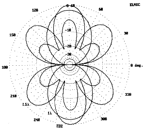
Most wire models using #12 to #18 show their maximum gain in 10-meter models with a length closer to 1225/f (MHz). However, such number-crunching devices are misleading. They obscure the fact that selecting the length of an EDZ is always a compromise between gain and another factor that dipole builders do not have to confront: side lobes. Fig. 3 overlays three EDZ patterns for wires of different lengths. The pattern with the greatest gain also has large side lobes and a narrow beam width. The other patterns show slightly less gain (less than -0.1 dB), but the shortest model (L= 1180/f (MHz)) also has the least off-axis gain. The cost of smaller sidelobes is a higher capacitive reactance at the feedpoint. In the end, selecting a length for an EDZ may be determined less by absolute gain potential than by the amount of off-axis QRM to be tolerated. Table 1 summarizes the modeled variations of gain and front-to-sidelobe ratio for 10 meter antenna lengths from 41.4' to 44.6' in free space.

                   EDZ Antenna Length vs. Gain and Sidelobes

Length      #12 Copper Wire               #18 Copper Wire
(Feet)      Gain (dBi)  Front-to-Side     Gain (dBi)  Front-to-Side
                        Lobe Ratio (dB)               Lobe Ratio (dB)

41.4        4.94        -15               4.90        -16

41.8        4.98        -13               4.94        -14

42.2        5.01        -11               4.96        -11

42.6        5.02        -10               4.98        -10

43.0        5.03        - 9               4.98        - 9

43.4        5.02        - 8.5             4.97        - 8.5

43.8        5.00        - 8               4.95        - 8

44.2        4.96        - 7               4.91        - 7

44.6        4.90        - 6.5             4.85        - 6.5

  delta G=0.13 dB  delta F-S=8.5 dB  delta G=0.13 dB  delta F-S=9.5 dB

Notes:
1.  Antenna model is for 28.5 MHz in free space.
2.  Gain figures are recorded to 2 decimal places for comparison purposes only.  Single digit
differences in the first decimal column are unlikely to be significant to performance.
3.  Front-to-side lobe ratios are estimated from antenna plots.  Higher accuracy is not required
to show the trend in sidelobe growth with antenna length.

Table 1.  EDZ antenna length vs. gain and front-to-side lobe ratio.
Had Fig. 3 showed further shortening of the antenna wire, eventually the side lobes would have disappeared--just as the antenna length approached a single full wavelength. Moving in the other (longer) direction, the main lobe gain quickly falls off to yield the traditional 6-petal pattern of a 1 1/2 wavelength antenna. Fig. 4 illustrates these extremes.
With the EDZ, there are also subtleties occasioned by antenna height. Within the usual amateur backyard building limits (20 to 70 feet antenna height), antenna gain will vary, with peaks at the 5/8, 1 1/8, and 1 5/8 wavelength heights and minima at the 7/8, 1 3/8, and 1 7/8 wavelength heights. Unfortunately, the 7/8 wavelength height, about 30 feet on 10 meters and 35 feet on 12 meters, is often a tempting and convenient amateur construction height. However, moving up a quarter wavelength in height (to about 39 feet on 10 meters) can increase gain by 1.6 dB over the 7/8 wavelength point and decrease the main lobe take-off angle by 4 degrees, with a consequent increase in radiation at the lower angles most favorable to DX. Above a height of 1 1/2 to 2 wavelengths, the gain fluctuations with height become insignificant, but the radiation at low radiation angles continues to increase. Half-wavelength dipoles also show such fluctuations at about the same heights, but to a much lesser degree. Gain variations with height result from reflected antenna currents being reinduced into the wire at phase angles that vary according to antenna height. The same phenomenon also creates a varying feed point impedance.3
The EDZ is a nonresonant antenna, displaying great capacitive reactance. Within the range of reasonable lengths (about 41.5' to 44.5' on 10 meters), the antenna shows a feedpoint impedance ranging from 175-j930 at the short end to 110-j640 at the long end. The impedance--both the resistive and reactive components--falls off more rapidly as the length passes the midpoint (43'), where the impedance is about 150-j840 .
Most commonly, hams feed the EDZ with open-wire or similar parallel transmission lines and an antenna tuner. This style of operation permits the operator to use the antenna on other bands in a way similar to the use of center-fed (double) Zepps in the 1930s. (I suspect that this fact contributed much to the name "extended double Zepp.") More recently, Yardley Beers reminded us that impedance matching need not be done at a distance from a highly reactive antenna. He developed a system of transformer matching between the antenna and a coaxial feedline. The secondary of the transformer not only provided the step-up ratio for the resistive component of the impedance, but as well provided the inductive reactance to compensate for the antennas natural capacitive reactance.4
Stub matching to a 50- coaxial feedline is also possible by selecting a line (for example, 450-Ohm parallel line) and, by calculation or experiment, choosing a length that results in a 50-Ohm resistive impedance when a suitable stub is connected in parallel across the junction of the matching section and the main feedline. A 44-foot long #14 wire 10-meter EDZ at about 35 feet above average ground would require a 450- (.95 VF) matching section just over 5-feet long and a parallel shorted stub of the same material just over 1.2 feet to provide a perfect match to 50- coax. Setting more precise dimensions than these would require information on the antenna's feedpoint impedance over the actual terrain of the site. Stub matching should result in a very reasonable 2:1 SWR bandwidth of over 800 kHz on 10 meters. See the Appendix to review the characteristics of stub matching and a method of calculating the elements of such a system.5
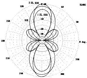
John Reh, K7KGP, was perhaps the first in recent times to experiment with 2-element arrangements of the EDZ, developing a 180-degree phased array of identical elements spaced 1/8 wavelength apart. The antenna is an extension of one version of the "two-section W8JK," which used 1-wavelength elements. Fig. 5 provides free space patterns of the 8JK and the phased EDZ antennas, both bidirectional arrays, along with a single element EDZ. The phased EDZ provides about 1.1 dB gain over the 8JK and about 2.9 dB gain over a single EDZ. This is equivalent to about 5.8 dB gain over a 1/2-wavelength wire dipole equally situated.
One advantage of the 180-degree phased EDZ array, like all other 180-degree phased arrays of any length, is the immunity of the antenna to variations in gain and impedance with changes in height. From 0.5 to about 2 , the gain of the array climbs quickly and then more slowly to essentially flat-top above 1.2 . The impedance remains quite constant, with the reactance varying by less than ▒ 1 . The difference in these characteristics from their counterparts in a single-wire antenna is due to the cancellation of radiation vertically (both incident and reflected), thus reducing the complexity of radiation interactions with the elements with changes in height. Fig. 6 compares the elevation patterns of a single wire EDZ with its 180-degree phased counterpart over medium earth at a height of 35 feet, about 1 at 10 meters.
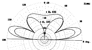
Fig. 7 shows the general outline of the phased array, along with two feed systems. Dimensions of the elements are not critical. Neither is the exact spacing. Construction can consist of two #18 copperweld or #12-14 copper wires with spreaders every 5 to 8 feet. For 10 meters, 4.5' lengths of thin wall PVC thin-wall conduit serve well. Hack saw slots into the ends to point 4.3' to 4.4' apart. Drill the ends of the cuts to pass the wire with friction. Leaving the burrs on the holes increases friction and holds the wires in place. Press the wires into the slots until they reach the holes. A 2-year test of this system showed no tendencies for the spreaders to slip from their initial positions, even without any adhesives or additional wire ties. Single end supports (towers, trees, guyed masts, etc.) are adequate for the antenna if the element ends, extended by 3/16 to 1/4 inch diameter sun-resistant synthetic rope, are attached to a longer and studier PVC length. Schedule 40 material is strong enough to permit the installation of eye-bolts. The end ropes pass through the eye-bolts and down to a tie off point for raising and lowering the antenna.

Feed systems are numerous, but only two are shown here. Section A. in Fig. 7 shows individual feedlines brought together with a reactance-cancelling stub, while Section B. shows a taut section of feedline between the elements, with a section dropped vertically to the coaxial cable junction. Either system will work over a narrow frequency range. It is possible to model feedline sections and correlate the results with feedline calculations using standard formulas.6 Calculations used standard 450-ohm line with a velocity factor of 0.95, while MININEC models used #18 wire spaced 0.083' (1") apart and NEC models specified transmission line lengths, impedances, and velocity factors. Of course, MININEC models do not treat feedline as feedline, but as part of the radiating structure where the fields tend to cancel each other. Nevertheless, the resulting figures came within construction variations of each other.
For an array consisting of two 44' #14 elements spaced between 4.3' and 4.4' at 28.5 MHz, the feedpoint impedances of the elements are each approximately 20-j650 . For reasonable variations in these dimensions (up to a half foot shorter and wire as thin as #18 copperweld), the resistive component will vary by an Ohm or 2, while the reactive component may range between -600 and -800 .
To achieve a Vee-shaped junction of two feedlines that in parallel produce a resistive impedance of 50 when a compensating parallel stub is added, requires a pair of lines, each nearly 5 feet long. Remember, one of the two lines has a half-twist to place the elements 180 out-of-phase. Where they join at the point of the Vee, a shorted stub only about an inch to an inch and a half long provides the proper compensation. Is the stub essential? Without the stub, the antennas feed impedance at the junction of the Vee is about 3 resistive and 12 reactive.
Only general figures are given here, because exact numbers depend upon knowledge of all the antenna and feedline variables for a given installation. In the area of line length required for a 50-Ohm match, the impedance shows a rapid change per unit length. Hence, a very fractions of an inch of line length may separate the impedance values generated by slight variations on a given version of the antenna. Trimming must be done in small increments. Series or parallel capacitors of a capacitive stub will compensate for the remnant reactance.
Using a taut 4.4' line between elements, with a further feedline centered at the 2.2' mark yields a different situation. Each line--a bit under 25 in length--shows an impedance of about 8.5-j300 at the junction point of the two, for a parallel combination of 4.25-j150 . Various models of this structure gave values of 3.9 to 4.3 resistive, with a reactive component of 140 to 175 . Connecting a single length of 450 feedline vertically from this junction a usable stub-main feed junction about 1.5 feet down the line. A very short shorted stub (about 2 inches long) in parallel across the junction will provide the 50- match to a coaxial feeder. Due to the very low resistive component of the junction, special care should be taken to ensure as lossless and weatherproof a set of connections as possible. Moreover, the very high reactance-to-resistance ratio indicates that the match will have a quite narrow bandwidth.
Models also suggest an untried scheme as a variant on Fig. 7B. Without a twist in the line, divide the antenna structure down the middle of the taut feedline, with each half fed in the center of its side of the line. Cross-connect the two resulting feedpoints in a parallel connection (essentially putting the twist at the connection), and the feedpoint impedance will be about 4.5-j150 , ready for the same connecting line as above.
Of course, the use of coax may be set aside and the parallel feeders run all the way to the station antenna tuner. Several factors recommend this method in preference to a stub match. First is the criticalness of the system tuning. Matching sections require lengths over which both resistance and reactance are changing by great amounts per unit of line length. With either the Vee or the flat-top stub-feed systems shown, the 2:1 SWR bandwidth is just over 100 kHz wide at 10 meters.
Second, the dimensions just given apply to a single height for the experimental antenna; alterations of antenna height from the 35' model height will require total recalculation. Indeed, the more critical the dimensions of a matching line and stub, the more ease of adjustment a good antenna tuner will provide.
The resulting array produces a pair of opposing narrow main lobes (28 to 32) with sidelobes about 50 off-axis and down about 12 to 14 dB, depending upon the exact choice of element lengths, spacing, and wire size. At a wavelength in height (35' at 10 meters), the take-off angle is about 13 with a -3 dB point at 7 above ground. Models also suggest that interaction between the antenna elements and the feeding-phasing structure may reduce gain by up to a dB from the theoretical optimum. The missing power reappears in the 90 off-axis directions, reducing the front-to-side ratio by a small but determinant amount. Nonetheless, for a fixed array where both forward and reverse directions may be useful but do not usually result in QRM, this antenna may be worth the work it takes to pruning it to a particular frequency and to a match with the transceiver.
If one could make the 2-element EDZ unidirectional, one might achieve a little more gain, plus have the advantage of reduced QRM from the rear. Theoretically, there are two ways of achieving this goal: a. create a parasitical beam, and b. phase-feed the rear element in a manner similar to the ZL Special. Table 2 shows a comparison of the free space gains of models of the full EDZ family, along with a standard half-wavelength wire dipole and the 2-element Yagi that has been used as a reference in earlier installments of these reports.
        Relative Free-Space Gains of Various Antennas in the EDZ Family

      Antenna                    Gain (dBi)

1/2 wl  Dipole                   2.07

1-el. EDZ                        4.85

2-el. reference Yagi             6.30

2-el. EDZ, 180-degree phase fed  7.85-8.10

2-el. EDZ, parasitic             8.70-9.25

2-el. EDZ, 135-degree phase fed  8.95-9.30

Notes:
1.  The "2-el. reference Yagi" refers to the modified W6SAI 10-meter beam used as a standard of
broadband 2-element design throughout this series.
2.  All values are derived from computer models and, except for the reference Yagi, average
several designs using, as relevant, different element lengths, spacings, and wire sizes.

Table 2.  The relative free-space gains of various antennas in the EDZ family, along with a
reference dipole and Yagi.
The idea for a two-element beam based on the double extended Zepp was first presented to me in 1991 by Brian Egan, ZL1LE, who proposed for his computer studies of a 15-meter model element spacing of 100 inches, with one element fed and the other a loaded reflector. My concern for keeping the wires properly spaced led me to consider closer spacing, something in the neighborhood of 1/8 wavelength spacing, as used in the ZL Special. The result was the development of two different, but related antenna concepts. One is a double extended Zepp version of the ZL Special, with phased feed. The other, following ZL1LE's lead, uses two elements of the same length, with one fed and the other loaded as a reflector. The computer says both should work quite similarly. The ZL Special version (referred to as the 5/4ZLS hereafter) offers the potential for eliminating loading coils. The symmetrical antenna (referred to as the ZL1LE hereafter) offers the potential for reversibility, allowing me to orient it toward Europe and toward down-under just by moving an accessible feedline.
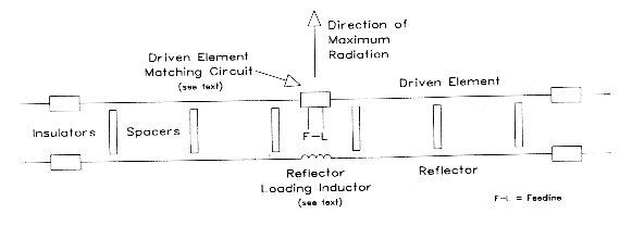
The original ZL1LE antenna used wide spaced elements. The modified version shown in Fig. 8, uses 1/8 wavelength spacing (4.39 feet) between two equal length elements. The forward element is fed, while the rear element is parasitic. However, to achieve any forward gain and significant front-to-back ratios, the rear element must be loaded inductively. With a carefully selected load, and minimizing losses in the load inductor, the antenna is capable of potentially superior performance. The gain at most heights averages across the design bandpass better than 14.5 dBi, or about 6.5 dB better than a dipole of equal height and orientation. The front-to-back ratio for various models runs from just under 20 dB to more than 30 dB.
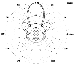
Fig. 9 shows the azimuth patterns for two model beams at a 35' height. The patterns with smaller sidelobes and a smaller front-to-back ratio (about 23 dB) uses #12 copper elements 41.67' long, spaced 4.39' apart and requires a reflector load of 1035 . The version with larger sidelobes and a higher front-to-back ratio uses 44' elements at the same spacing, with the same wire and a 685 reflector load reactance. As with any member of the EDZ family, balancing various characteristics determines the final choice of design. In any event, one must model the parasitic EDZ beam over real ground, as in Fig. 9, to gain a perspective on the actual characteristics. The free space pattern yields a pattern whose rear lobes look like miniatures of the forward lobes, a picture that does not hold over real ground.
Table 3 compares the modeled performance of the ZL1LE antenna in two versions to the performance of a single element EDZ and of a 2-element 180-degree phase-fed array. Also noted are the necessary changes in loading inductor for the parasitic element to achieve maximum front-to-back ratio at each height. Below a height of about 2 , the parasitic EDZ beam in almost any form is height sensitive with respect to gain, front-to-back ratio, and the required loading inductance to achieve maximum front-to-back ratio. A height of about 1 provides the best combination of gain and front-to-back ratio. In fact, experimental models of the antenna appear to lose much of their dx potential if not at least 1 above ground.7
Comparisons of Antenna Models Based on the Extended Double Zepp
HeightGain Front-to- Front-to S/L Beam Source Source Load
(Feet)(dBi) Back Ratio Side Ratio Gain Width Resistance Reactance Z=10+jXL
(dB) (dB) (dBi) (░) R (Ohms) -XC (Ohms) XL (Ohms)
Single Wire EDZ (42.8' Elements, #18 Copper)
F.S. 4.9 10 -5 32 162 840
20 11.3 10 1 36 128 860
25 10.0 10 -1 34 150 810
30 9.6 10 -1 34 193 830
35 11.0 10 1 34 159 870
40 11.0 10 1 32 137 830
45 10.0 10 0 32 173 820
2-Element EDZ, 180° Phase-Fed Array (42.8' Elements, #18 Copper)
F.S. 7.8 15 -7 30 26.4 (x2) 820
20 12.2 17 -5 32 26.3 822
25 12.8 16 -3 32 25.2 820
30 12.7 15 -2 32 26.8 819
35 12.9 15 -3 32 27.0 820
40 13.2 15 -3 32 25.9 820
45 13.2 15 -3 32 26.1 819
2-Element Parasitic EDZ Beam (42.8' Elements, #18 Copper)
F.S. 8.7 16.4 11.8 -3.1 32 89.8 775 950
20 14.3 18.0 13.5 0.8 34 80.7 792 905
25 13.6 11.9 13.0 0.5 34 76.6 777 945
30 13.1 18.1 12.3 0.7 32 97.1 760 980
35 14.4 25.3 12.8 1.6 32 96.0 775 935
40 14.4 13.2 12.0 2.4 32 79.1 785 930
45 13.8 14.3 11.9 1.9 32 88.3 768 970
2-Element Parasitic EDZ Beam (41.67' Elements, #12 Copper)
F.S. 8.8 15.4 14.0 -5.0 34 102.0 830 1055
20 14.5 16.9 15.8 -1.3 36 94.8 852 1000
25 13.7 11.1 14.0 -0.3 36 86.2 832 1050
30 13.5 16.9 14.7 -1.2 34 109.3 813 1095
35 14.5 23.4 15.1 -0.6 34 110.0 830 1035
40 14.6 12.5 14.0 0.6 34 89.2 843 1025
45 13.9 13.4 14.0 -0.1 34 99.1 822 1080
Notes:
1. F.S. = free space 2. Sidelobe figures estimated from graph for bidirectional antennas.
3. Loading coil assumed to have an approximate Q of 100
Table 3. Comparisons of antennas based on the Extended Double Zepp as modeled at typical
amateur construction heights and optimized (where necessary) for maximum front-to-back ratio.
The source impedance for the antenna shows a large capacitive reactance which requires compensation. Assuming the use of a suitable inductance to eliminate the reactance, the feedline impedance, now only resistive, is roughly twice that of the normally used 50-ohm coaxial cable. A 2:1 quarter-wave matching section of 75 ohm cable cut to design center frequency would likely yield an acceptable match. A linear choke, such as the W2DU ferrite choke balun, would be apt between the feedline and the matching section.
Since this antenna requires inductors in both elements, one to cancel the series capacitive component of the source impedance and the other to load the reflector, the system holds potential for being used as a fixed beam whose direction is reversible. However, if the components are mounted at the antenna, it is unlikely that anyone would climb a structure to readjust the inductor values. However, the inductors need not be mounted at the antenna.
Low loss parallel feedline--450-ohm is recommended for its ability to withstand power and weather--permits both matching inductors to be mounted closer to the ground. A wavelength (assuming .95 velocity factor) at 28.5 MHz is about 32.8 feet, and a half wavelength is 16.4 feet. For 10-meter antennas at 20 or 35 feet, feedline runs to a platform near the ground are feasible with a length of line that permits the impedance conditions at the element centers to replicate. Using rotary or tapped inductors, one can adjust the loading and the compensating inductors with comfort and ease. A chart of settings would ensure quick adjustment. Installing a coaxial connector near each coil would permit shifting the feedline from one element to the other, thus permitting the direction of the beam to be reversed.
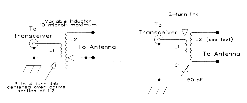
The reason for employing this scheme is to achieve a reversible fixed beam. A 44'-element beam was constructed for reversible parasitic operation. I mounted a rotatable 5' plank on the end of a 4-by-4 sunk in the ground. One end of the plank held the reflector inductor, the other held the driven element matching system. Rotating the plank and reconnecting the feedlines reversed the antenna. A modified version of the Beers matching system converted the driven element impedance to 50-ohm coax values. Fig. 10 shows two systems tried with equal success. One uses a rotary coil with a fixed 3-turn link of #18 solid hook-up wire. The other uses a fixed 2-turn link over a fixed coil of 8 turns of 1.5" diameter, 10 turns per inch stock, with a 50 pF variable capacitor in series with the link to control the degree of coupling. Either system amounts to installing an antenna tuner at the antenna, a multiple of a half wavelength below it.
Tuning the inductor to maximum front-to-back ratio requires a variable inductor and a signal source several wavelengths behind the antenna. Coil variability should range of 4.0 to 6.5 ÁH to cover a 10-meter reactance range of 770 to 1100 . A 10 ÁH variable inductor picked up at a hamfest provided sufficiently sharp tuning for tests. Of course, weather-proofing the tuning components is essential for this scheme.
Test results showed that the parasitic EDZ beam has excellent gain and reasonably good front-to-back ratio for the frequency to which everything is tuned. However, without retuning--especially the reflector inductor--everything goes to pot very quickly as one tunes off frequency, especially downward. SWR curves do not necessarily provide significant information in this connection. After adjustment of all the variables for 28.5 MHz, an SWR meter in the coaxial feedline showed under 2:1 between 28.1 and 28.9 MHz. However, below the design frequency, the beam had lost its unidirectional characteristic.
Table 4 models the effects of off-frequency use of the parasitic EDZ. If the value of XL is low by 10%, the reflector becomes a director, and the beam reverses its direction. Using values of XL optimal for a frequency 0.5 MHz higher in the 10-meter band results in performance similar to that of the bidirectional array. A higher XL value, optimal for a lower frequency, results in a gradual drop in gain and a more rapid drop in front-to-back ratio. If one must choose a single inductor value for the reflector coil, the best choice is the optimum value for the lowest operating frequency in the band. However, the large variation in optimum inductance required across a wide band like 10 meters suggested that the parasitic EDZ beam is best used as a fixed-direction, fixed-frequency or narrow band antenna. For that use, however, it is inexpensive compared to a Yagi with similar gain and front-to-back ratio.
   Performance of a 2-Element Parasitic EDZ with Nonoptimum Reflector Loading

Measurement Optimum Frequency Optimum Load      Reactance   Gain        Front-to
Frequency   for XL Used       Reactance (XL)    Used (XL)   (dBi)       Ratio (dB)

28.0 MHz    28.0 MHz          1030 Ohms         1030 Ohms    14.6       22.3
28.5                           905              1030         13.7        8.0
29.0                           795              1030         13.0        5.2

28.0 MHz    28.5 MHz          1030 Ohms          905 Ohms   -12.4       -0.9
28.5                           905               905         14.6       22.3
29.0                           795               905         13.6        8.0

28.0 MHz    29.0 MHz          1030 Ohms          795 Ohms   -12.9       -3.4
28.5                           905               795        -12.5       -0.9
29.0                           795               795         14.6       22.0

Note:  Modeled antenna used 2 42.8' elements, #18 copper wire space 4.39' apart at a height of 20'
over medium earth.  Similar results were obtained with other "equal-element" parasitic models at
various heights above ground.

Table 4.  Performance of a representative 2-element parasitic EDZ with nonoptimum reflector loading.
One untested potential for the ZL1LE antenna is at 2 meters, where materials and dimensions make the antenna self-supporting. Using 0.75" diameter aluminum tubing, one can construct a beam with a driven element 8.2' long and a reflector 8.6' long, spaced just over 10" apart. Models indicate a reflector load between 250 and 305 ohms at 144.5 MHz. The source impedance is about 50-j290 , which simplifies the process of matching the antenna to coaxial cable to the elimination of the reactance alone. Due to the increase in element diameter to element length ratio, bandwidth increases over HF wire models and may cover a full megahertz of the band without undue loss of gain or front-to-back ratio if the antenna is optimized near the low end of the desired frequency range.
Such antennas almost exist. One commercial advertisement includes a double 5/8-wavelength vertical, that is, two such antennas end to end. The same ads indicate that some directionality will result if the antenna is mounted on the side of a tower, which apparently forms an untuned reflector. Perhaps some day a manufacturer who can control the reflector loading reactance within tight specifications may produce a true 2-meter ZL1LE.
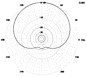
The horizontal advantages of the 2-meter antenna for low-end CW and SSB operations, despite bandwidth restrictions, are the same as for HF models. However, Fig. 11 shows an azimuth pattern of the antenna mounted vertically, with the center 35' above ground. The bandwidth to half-power points is about 135 and the gain is over 13 dBi. The utility of such an antenna at a ham station for both repeater and Packet work seems obvious, and three of these antennas arrayed around a tower might well increase the range of any repeater. The lack of suitable VHF test equipment must leave the development of a working model of the 2-meter ZL1LE to others.
The phase-fed version of the two element EDZ beam consists of two unequal length elements spaced 4.31' apart for 28.5 MHz. The directly-fed forward element is 42.3 feet long, while the phase-fed rear element is 44.7 feet long. Configured as a wire beam, this assembly is unidirectional. Computer models show a peak gain of 14.7 dBi across the 1 MHz design bandwidth, with an average front-to-back ratio of about 20 to 23 dB, peaking at about 30 dB. The beamwidth is a narrow 34 degrees. All of these figures apply to a 35-foot height for the antenna. Fig. 12 shows the pattern of the antenna as optimized for 28.5 MHz.
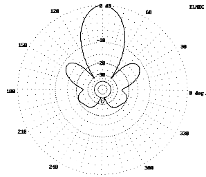
Experience with ZL-Special would suggest that with 1/8th-wavelength spacing, the rear element should be fed 135 out-of-phase with the forward element. Modeling suggests otherwise. The model whose pattern appears in Fig. 12 is current phase fed at 143 to achieve maximum front-to-back ratio. Since the proposed method of feed is a twisted parallel feedline section, the modeling technique was altered. The rear element is modeled in the opposite direction from the forward element, and the phasing directly applied as -37 to the rear element source point. This technique yields identical pattern figures, but provides correct information on current and voltage amplitudes and phases for use in calculating phasing lines.
The chief difficulty in implementing the 5/4ZLS version of the 2-element EDZ is feeding two elements with highly reactive components in such a way as to ensure that equal power flows to both elements and that the rear element is about 143 out of phase with respect to the forward element. The source impedances for the model under discussion are 100-j830 and 5-j660 for the forward and rear elements respectively. I have been unable to discover any cable of any length that will provide the proper phasing in the manner of the traditional ZL Special. Moreover, the demands of this antenna may exceed even the flexibility of a phasing network. The high reactances at the feedpoint place any network in a region which is experiencing very rapid changes in current phase and in impedance per unit length. Regretfully, the 54ZLS has had to be consigned to the realm of antennas with theoretical potential but no present feasibility.
Nevertheless, models do suggest that the dimensions of this antenna, when fed as a Yagi, will produce excellent unidirectional gain and a good front-to-back ratio with a reflector load of 675 . In essence, the ability to adjust the reflector loading substitutes for a phasing line in bringing the reflector current to the correct magnitude and phase to achieve a deep rear null. However, no unidirectional EDZ array will do much better than about 20 dB front-to-rear ratio when including all parts of the rear lobes.
It is worth noting, however, that what we call "phasing" lines in antennas like the ZL Special are actually impedance transformers, with or without the half twist. Explorations of models using approximately 1/8th half-twist parallel transmission lines between two identical elements produced an alternative means of matching an EDZ to 50- coaxial cable. A two-element version of the 10-meter EDZ with such a connecting section made up from 600- (.95 VF) parallel line shows an almost perfect impedance for coaxial-cable feed. The gain of the antenna is about the same as a single element EDZ (about 11 dBi at 35 feet over medium earth), with a slight (less than 0.9 dB) difference between the two main lobes. The SWR is less than 2.5:1 over the first MHz of 10-meters. For the cost of an additional element and some separators, the builder can produce a coax-fed adjustment-free EDZ.
Understanding the possibilities for EDZ arrays and beams depends, as we have seen, on understanding the basic properties of the single element EDZ antenna. Two-element arrays, either bidirectional or unidirectional are possible and feasible--if they fit the operating needs and circumstances of a particular station. As wire beams, they are fixed and thus fit for point-to-point communications. Their narrow bandwidths and beamwidths reinforce this type of use. Moreover, they are not forgiving of casual building and tune-up practices.
There remains much to be learned about the behavior and the possibilities of EDZ beams. A bit of that data appears in other notes at this site, for example, EDZ Beam Update; Feeding the EDZ; and Phased Yagis, EDZ Beams, and Landsdorfer-Sacher Yagis.
If thelimiting factors factors are not deterrents to building one of the EDZ family of beams, but part of the needs of a station, then the operator can expect considerable gain over many other types of wire antennas. Moreover, the cost of these antennas, including wire elements and feedlines, is well below the cost of Yagis with equal gain (and equal front-to-back ratio for the ZL1LE). EDZ beams may have a small but not insignificant niche in the spectrum of amateur antennas. I do not recommend them, since recommendation would require a detailed knowledge of too many variables directly related to the communications situation in which the antenna might play a part. However, I do recommend further experimentation, modeling, calculation, and ingenuity in pursuit of getting the most out of this interesting family of antennas. EDZs and other nonresonant arrays may have gone unjustly neglected in our dipole-and-coax age.8
1. This tongue-in-cheek introduction does have a serious point. The Jones handbook mentions the 5/8 wavelength vertical, especially as a broadcast antenna, as early as 1936, if not before. See Frank C. Jones, Jones Radio Handbook, 3rd Ed. (San Francisco: Pacific Radio Publishing Co., 1936), pp. 73-74. However, see Hugo Romander, W2NB, "The Extended Double-Zepp Antenna," QST, June, 1938. The antenna remained much neglected after this initial introduction to the ham community.
2. Yardley Beers, "The 5/4-Wavelength Dipole: A Revival," Communications Quarterly (November, 1990), pp. 40-41. Jerry Hall, Ed., The ARRL Antenna Book (Newington, ARRL, 1991), p. 8-34.
3. See L. B. Cebik, "The Effects of Height on Other Antenna Properties," Communications Quarterly (Fall, 1992), pp. 57-79.
4. Beers, "The 5/4-Wavelength Dipole: A Revival," pp. 41-44.
5. K7KGP's 12-meter EDZ, shown in recent ARRL Handbooks, can mislead builders, since his stubless match applies only to the antenna feedpoint impedance figures he lists. See The ARRL Handbook (Newington: ARRL, 1992), p. 33-11. The matchline he specifies leaves an Ohm or 2 of remnant reactance, much too little to be of concern. Except in very rare cases, other feedpoint impedance figures will require a stub to compensate for reactance at the junction of the matchline and the main feedline. The Appendix to this article provides a method of directly calculating both the matchline and stub elements of a stub-matching system.
6. See Terman, Radio Engineer's Handbook (New York: McGraw-Hill, 1943), pp. 185-186, among other sources (for example, Johnson's Antenna Engineering Handbook, 3rd Ed.), for the basic formulas for calculating the impedance, current, and voltage along a lossless transmission line for any length from the load. Fortunately, these formulas are amenable to simple basic programming that, in addition to figures for specific line lengths, will produce charts of results for any desired interval. Such charts permit estimation of desirable line lengths within trimming range. As previously noted, it is also possible to use these formulas to calculate required stub-matching systems; see the Appendix.
7. A 2-element Yagi at 35' provided stronger signals on 10 meters on the eastern U.S. to VK/ZL path than an initial experimental model of the EDZ beam at 25', despite the fact that models estimated roughly equal radiation in the 5 to 10 elevation region. Raising the wire antenna resolved the problem. However, the experience impressed upon me the importance of choosing antenna heights such that the lowest required path angle clears fields of obstructions, such as nearby woods with 70' trees and the like. The effect can be dramatic.
8. All patterns shown in this discussion were plotted on ELNEC 3.02, but figures cited have been cross-checked on various programs and by various means of calculation (including versions of NEC-2 and NEC-4).
As long as hams wish to use or experiment with antennas like the Extended Double Zepp and others that present complex feedpoint impedances, stub matching will remain one alternative method of matching the antenna to a 50- feedline. Most discussions of stub matching, however, appear almost wholly in qualitative terms. The purpose of this discussion it to convert that discussion into quantitative terms. We shall proceed by reviewing the basic concept of stub matching, presenting the basic equations for calculating the elements of a stub-matching network, and finally using a simple BASIC implementation of those equations to solve a couple of exemplary problems.
Most antenna manuals give the simple equations for calculating the reactance of both shorted and open transmission line stubs. However, these treatments regularly omit similar equations for calculating the length of the line between the antenna and the stub-feedline junction. So let's begin again.
Fig. 13 shows the basic structure of a typical stub-matching system. It consists of the antenna with its complex feedpoint impedance, a length of matching-feedline (the Line) leading to the critical junction, a reactive Stub, and the main feedline (the Feed) leading to the power source, ordinarily a transmitter or transceiver. The functions of the antenna and the main feedline are well-known, but the functions of the other two elements require brief comment.
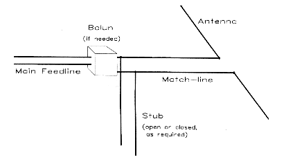
The matching-feedline operates as an impedance transformer. When there is a complex antenna feedpoint impedance or a mismatch between the antenna impedance and the matching-feedline impedance, the overall impedance, as well as the resistive and reactive components of that impedance, will vary along the line. These values are normally given as series values. If the line type (that is, its characteristic impedance) is properly chosen, at some point along the line, the resistive component of the impedance will be of such a value that its corresponding parallel value will equal the characteristic impedance of the main feedline. This point defines the correct length of matching feedline to use.
Ordinarily, at the junction of the matching-feedline and the main feedline, there will also be a reactive component to the overall impedance. Although usually given as a series value, it too has a corresponding parallel value. A reactance of the opposite type but of the same magnitude will compensate for the junction reactance. In this exercise, the compensating reactance will be composed of a feedline stub, even though lumped components (capacitors or inductors) are also usable with somewhat greater losses in some instances. Compensating for the parallel reactance will leave a parallel resistance equal to the main feedline. With the reactance compensated, the resulting series resistance value will be the same value, thus effecting a match to the main feedline.
Often left to graphical analysis along with some miscellaneous calculations, the calculation of match-line and stub systems can be direct. With the advent of home computers and BASIC, the reputed tediousness of the calculations is no longer a hindrance. Indeed, a simple computer program is faster than most graphical methods (some of which have been computerized).
The process begins by understanding that along a match-line, we are seeking the point at which the parallel-equivalent value of the series resistance is equal to the characteristic impedance of the main feedline. Associated with these values is a value of series reactance and its parallel equivalent. If we call the series resistance and reactance the target values, then we define RT and XT. Let ZF be the characteristic impedance of the main feedline. Then, using the series-to-parallel resistance conversion equation,

Solving for XT2, we get

Before using equation (2), we must calculate the reflection coefficient, rho, (actually its square) of the antenna-to-match-line system. Let the match-line characteristic impedance by ZM. Then, using the antenna feedpoint impedance, RL ▒ jXL, we can calculate.

Using this figure for rho, we can then calculate the value of series resistance at the point in the line defined by equation 2, using that equation to remove reactance values from the calculation of RT:

The target value of reactance is, of course, the square root of equation 2.
The equation, in various forms, for calculating the impedance, Zin, anywhere along a transmission line back from a load, ZL, is well known.1 That equation can be rewritten as separate equations for Rin and Xin, which will be more useful for present purposes. We shall use equations for lossless lines for three reasons. First, the lengths of line involve--all well under a wavelength, have losses far less significant than other potential error factors that enter the use of matching stubs. Second, for most types of transmission line, the most imprecise figure is the velocity factor of the line to be used, and most ham do not have access to laboratory grade measuring equipment to bring experimental determination of that figure under 5%. Third, physically replicating a calculated antenna, especially one with a significant reactive component at the feedpoint, usually results in departures from calculated values. Nevertheless, a calculation of the anticipated matching line and stub lengths will do much better than put one in the ball park: it will allow one to make a close play at the plate.
Since we wish the matching line to yield a resistive impedance component that correlates with the characteristic impedance of the main feedline, we may begin with the formula that has appeared in the ARRL Handbook in the 80s and early 90s.2

where RL is the resistive component of the antenna impedance, XL is the reactive component of the antenna impedance, ZO is the characteristic impedance of the matching section transmission line, and Rin is the resistive component of the impedance at a distance lr from the antenna along the line. In this exercise, Rin is precisely our target value of resistance, RT. For our purposes, we shall assume that lr is in radians, although in general, it might also be in degrees relative to a wavelength at the frequency of interest for the antenna.
The matching line length calculation simply requires us to solve equation (1) for lr and to convert that length in radians into degrees and feet. A rewrite of equation (1) yields a quadratic:

Solving for lr, we obtain

Note that there are two solutions, since for every 180 of line length (under mismatch conditions), there will be two points at which the resistive component of the impedance has the same value.
The limiting case is where the value under the radical in equation (7) goes to less than zero. This condition indicates that, with the combination of line values chosen for the antenna impedance values measured or derived from a modeling program, the resistive component never reaches the chosen main feed line characteristic impedance. The solution to this problem is usually to select a different transmission line for the matching line section.
Equation (7) returns two lengths in terms of radians along a wavelength. We can convert these lengths to a more familiar measurement in degrees by the equation

where lr is the length in radians and ld is the length in degrees. Transformation of these lengths into feet involves the equation

where Lf is the required length in feet, fMHz is the frequency of interest in MHz for the antenna, and VF is the velocity factor of the matching section transmission line.
Using the value of lr, we may calculate the remnant reactance by using the Handbook formula for Xin:

where all of the variables have the same meaning as in equation (7). Applying equation (10) to the two lengths resulting from equation (7) will yield opposing values of reactance. We may choose to match either with a stub. Alternatively, we may calculate the reactance values directly from the square root of equation (2), assigning the signs this way: the reactance associated with the shorter line length will have the sign of the reactance at the antenna feedpoint.
For the stub calculations, we shall first convert the reactance into a parallel value to facilitate mechanical connections for the stub.

where Rs is the main feedline characteristic impedance, Xs is the calculated input remnant reactance, and Xp is the equivalent parallel reactance which the stub is to compensate.
Reversing the signs of the reactances gives the values that must be returned by appropriate compensating stubs. The length of a shorted stub, when the desired reactance is known, is given by

and the length of a corresponding open stub is given by

where Xin is the desired reactance, ZO is the characteristic impedance of the transmission line used for the stub, and lS and lO are the lengths of shorted and open stubs, respectively. Since the values of lS and lO are in radians, they can be converted into feet by the same means used to convert the length of the matching line.
The final step is to select the best combination of matching line and stub for the proposed antenna. Ordinarily--for least loss and mechanical simplicity--the combination with the shortest matching line and stub is most desirable.
The calculations for a stub-matching system lend themselves to a simple utility program in BASIC or almost any other language. Fig. 14 gives the listing for my own program, replete with my personal programming quirks. Lines 10-130 set up the input values for the calculation. Lines 140 through 170 calculate the target resistance value along the match-line. Lines 180-440 calculate the length of the matching-line section and the series resistance and reactance values at that point. The equations is broken down into components to precalculate repetitive parts. Line 200 catches the case where the value under the radical is less than zero. Lines 360-410 calculate the reactance for each of the solutions to equation (7), once more with the relevant equation broken down into segments or normalized. (These lines also recalculate the input resistance of the matching line; I put this in while setting up the program as a check and never took it out, since it involves only a few extra lines. The technique is useful for error catching during the program writing process. However, using RT and XT and bypassing these steps would shorten the program somewhat.)
10 'file STUB.BAS
20 CLS:COLOR 11,1,3:CLS
30 PRINT" General Solutions for Stub Matching,": PRINT" given Antenna R & X plus Line, Stub, & Feed Zo":PRINT" L. B. Cebik, W4RNL":PRINT
40 PRINT"For any antenna load R and X, this program finds the Line and Stub length neededto match any feedline Zo, if a match is possible with the proposed Line, Stub, and Feed Zo values.":PRINT
50 INPUT "Enter Antenna Load Resistance in Ohms ",RL
60 INPUT "Enter Antenna Load Reactance in Ohms ",XL
70 INPUT "Enter Frequency (in MHz) ",FQ
80 INPUT "Enter Zo of Line (from antenna to stub) ",ZL
90 INPUT "Enter Velocity Factor of Line (as decimal) ",VFL
100 INPUT "Enter Zo of Feed (from stub junction to rig) ",ZF
110 INPUT "Enter Velocity Factor of Feed ",VFF
120 INPUT "Enter Zo of Stub (from line-feed junction) ",ZS
130 INPUT "Enter Velocity Factor of Stub ",VFS
140 RLS=(RL*RL):XLS=(XL*XL):ZLS=(ZL*ZL):RIS=(RI*RI)
150 RHOS=(((RL-ZL)*(RL-ZL))+XLS)/(((RL+ZL)*(RL+ZL))+XLS)
160 RT=((ZL*ZL)*(1-RHOS))/((ZF*(RHOS-1))+((2*ZL)*(RHOS+1))):RI=RT
170 'IF (ZF*RT)-(RT*RT)<0 THEN 350 ELSE XT=SQR((ZF*RT)-(RT*RT))
180 A=(XLS/ZLS)+(RLS/ZLS)-(RL/RI):B=2*(XL/ZL):C=1-(RL/RI)
190 IF A=0 THEN A=1E-08
200 NUM=((B*B)-(4*(A*C))):IF NUM<0 THEN 350
210 TLP=(B+SQR((B*B)-(4*(A*C))))/(2*A)
220 TLM=(B-SQR((B*B)-(4*(A*C))))/(2*A)
230 LP=ATN(TLP):LM=ATN(TLM)
240 PI=3.141592654#
250 LPD=(LP*180)/PI:LMD=LM*180/PI
260 IF LPD<0 THEN LPD=180+LPD
270 IF LMD<0 THEN LMD=180+LMD
280 LPF=(LPD*VFL)/(.3660131*FQ):LMF=(LMD*VFL)/(.3660131*FQ)
290 PRINT"Possible line lengths are A. ";LPF;"feet and B. ";LMF;"feet."
300 LR=LP:GOTO 360
310 RIA=RI:XIA=XI:PRINT"For Line length A., Rs= ";RI;"Ohms and Xs= ";XI;"Ohms."
320 LR=LM:GOTO 360
330 RIB=RI:XIB=XI:PRINT"For Line length B., Rs= ";RI;"Ohms and Xs= ";XI;"Ohms."
340 GOTO 440
350 IF NUM<0 THEN PRINT"There are no possible solutions with this combination of of antenna impedance and line impedance.":GOTO 710
360 IF RL=0 THEN RL=1E-08
370 RA=RL/ZL:XA=XL/ZL:T=TAN(LR):TS=T*T
380 DA=(1-(XA*T))*(1-(XA*T)):DB=(RA*T)*(RA*T):DN=DA+DB
390 RS=RA*RA:XS=XA*XA
400 RN=RA*(1+TS):XK=XA*(1-TS)
410 XM=((1-RS)-XS)*T:XN=XK+XM:RZ=RN/DN:XZ=XN/DN:RI=ZL*RZ:XI=ZL*XZ
420 IF LR=LP THEN GOTO 310
430 IF LR=LM THEN GOTO 330
440 PRINT"For a record of these calculations, press <Print Screen>."
450 PRINT:PRINT"Press <C> to continue."
460 I$=INKEY$:IF I$="c" OR I$="C" THEN GOTO 470 ELSE 460
470 CLS:PRINT:PRINT"Stub Calculations:":PRINT
480 PRINT"Option A: Rs= ";RIA;" and Xs= ";XIA;" Ohms
490 XPA=((RIA*RIA)+(XIA*XIA))/XIA:XCOMPA=(-1*XPA)
500 PRINT"The required parallel stub reactance to compensate is ";XCOMPA;"Ohms."
510 LRL=ATN(XCOMPA/ZS):LDL=(ABS(LRL)*180)/PI
520 IF XCOMPA<0 THEN LDL=180-LDL
530 LFL=(LDL*VFS)/(.3660131*FQ)
540 LRC=ATN(ZS/XCOMPA):LDC=(ABS(LRC)*180)/PI
550 IF XCOMPA>0 THEN LDC=180-LDC
560 LFC=(LDC*VFS)/(.3660131*FQ)
570 PRINT:PRINT"The required SHORTED STUB length is ";LDL;"degrees or ";LFL;"feet.
580 PRINT"The required OPEN STUB length is ";LDC;"degrees or ";LFC;"feet.
590 PRINT:PRINT:PRINT"Option B: Rs= ";RIB;" and Xs= ";XIB;" Ohms
600 XPB=((RIB*RIB)+(XIB*XIB))/XIB:XCOMPB=(-1*XPB)
610 PRINT"The required parallel stub reactance to compensate is ";XCOMPB;"Ohms."
620 LRL=ATN(XCOMPB/ZS):LDL=(ABS(LRL)*180)/PI
630 IF XCOMPB<0 THEN LDL=180-LDL
640 LFL=(LDL*VFS)/(.3660131*FQ)
650 LRC=ATN(ZS/XCOMPB):LDC=(ABS(LRC)*180)/PI
660 IF XCOMPB>0 THEN LDC=180-LDC
670 LFC=(LDC*VFS)/(.3660131*FQ)
680 PRINT:PRINT"The required SHORTED STUB length is ";LDL;"degrees or ";LFL;"feet.
690 PRINT"The required OPEN STUB length is ";LDC;"degrees or ";LFC;"feet.
700 PRINT:PRINT"Press <Print Screen> to complete the record of calculations."
710 PRINT:PRINT"For another run, press <A>; to quit, press <Q>."
720 I$=INKEY$:IF I$="a" OR I$="A" THEN 10 ELSE IF I$="Q" OR I$="q" THEN 730 ELSE 720
730 END
Fig. 14. Program listing for STUB.BAS
The results of the calculations so far can be recorded on paper by a program pause and a <Print Screen> command. Since two screens of material will fit on one piece of paper, do not <Form Feed> at this time. Lines 450-710 calculate the required parallel reactive components and the stub values that will compensate for them, two values for each line length. A second <Print Screen> will combine this information with the input values for a complete record. A sample double screen printout appears in Fig. 15. The antenna is a 10-meter (28.5 MHz) Extended Double Zepp with a 450- stub match system for a 50- feedline where the EDZ models a feedpoint impedance of 141-j694 . Option A is 5.0' with a shorted stub of 1.2' or an open stub of 9.4', and option B is 5.5' with a shorted stub of 15.2' or an open stub of 7.0'. Option A and a shorted stub provide the mechanically simplest system to implement. You can truncate the decimals in the results almost anywhere, since in most cases, results to the nearest ohm and tenth of a foot will be close enough to permit antenna system adjustment.
For any antenna load R and X, this program finds the Line and Stub length needed to match any feedline Zo, if a match is possible with the proposed Line, Stub, and Feed Zo values.
Enter Antenna Load Resistance in Ohms 141.36
Enter Antenna Load Reactance in Ohms -693.56
Enter Frequency (in Mhz) 28.5
Enter Zo of Line (from antenna to stub) 450
Enter Velocity Factor of Line (as decimal) .95
Enter Zo of Feed (from stub junction to rig) 50
Enter Velocity Factor of Feed .66
Enter Zo of Stub (from line-feed junction) 450
Enter Velocity Factor of Stub .95
Possible lines lengths are A. 5.038553 feet and B. 5.485493 feet.
For line length A., Rs= 41.10245 Ohms and Xs= -19.12316 Ohms.
For line length B., Rs= 41.10246 Ohms and Xs= 19.12327 Ohms.
For a record of these calculations, press <Print Screen>.
Press <c> to continue.
Stub Calculations
Option A: Rs= 41.10245 Ohms and Xs= -19.12316 Ohms.
The required parallel stub reactance to compensate is 107.4669 Ohms.
The required SHORTED STUB length is 13.43154 degrees or 1.223229 feet.
The required OPEN STUB length is 103.4315 degrees or 9.419658 feet.
Option B: Rs= 41.10246 Ohms and Xs= 19.12327 Ohms.
The required SHORTED STUB length is 166.5685 degrees or 15.16963 feet.
The required OPEN STUB length is 76.56851 degrees or 6.973203 feet.
Press <Print Screen> to complete the record of calculations.
For another run, press <A>; to quit, press <Q>.
One caution is necessary with the use of calculating programs. Unlike graphical solutions, calculating programs give no feel for the sharpness or broadness of the results, that is, how small physical variations from the calculations will affect the adjustments. In general, the higher the ratio of reactance to resistance at the antenna feedpoint, the sharper the curve. In these cases, small physical variations may require extensive adjustment of the calculated lengths.
Recent ARRL Handbooks have presented an interesting 12-meter EDZ cut to a length that provides a feedpoint impedance of 142-j555 .3 With 450- transmission line (VF=.95), both options yield 5'5" of matching line with negligible reactance, obviating the need for a stub. The impedance presented by the matching line to the coax is 55 . In fact, using the program with a feedline impedance of 50 produces a "no possible solution message." The lesson is that before giving up on a combination, try raising or lowering the feedline impedance by 10% to see if a solution emerges. The resulting SWR on the coax will be well within limits. However, K7KGP's antenna is quite unusual, and exact reproduction or scaling for other bands may require extensive on-site adjustment.
These examples only sample the use of a utility BASIC program in making matching-section calculations. The limits of stub matching are far wider than these examples. Of course, modeling the results on NEC with transmission-line capabilities permits all calculations to be verified.
1 See, for example, Terman, Radio Engineer's Handbook, p. 186, or Kuecken, Exploring Antennas and Transmission Lines by Personal Computer, pp. 180-181.
2 See, for example, p. 16-2 of the 1987 Handbook for a normalized version of the equation or p. 16-3 of the 1992 Handbook for a non-normalized version.
3 See, for example, the 1992 Handbook, p. 33-11.