


|
|
 |
 |
 |
|
|
Antentop is FREE e-magazine devoted to Antennas and Amateur Radio an
Special page devoted to
The Wireless Power Transmission System

Custom Search
|
ANTENTOP-
02- 2003, # 003 |
The
Wireless Power Transmission System |
|
|
|
||
|
In a detailed analysis of forces involved Curry shows
that radiators with a capacitance of .0053 microfarads operating
at 100 KHz with signal generator output of 200 volts coupled with
a biasing potential of 1000 volts will produce a force from its
charge displacement of 26,500 dynes.[14] On the receiving side Curry states that the charge gradient
can be expected to attenuate substantially at even moderate distance
from the point of transmission. As an example he notes that if
a signal intensity of 10,600 dynes at the point of transmission
is reduced one billion times the "standing wave of the signal
energy will therefore be charged with a force differential of
1.06 x 10⁻⁵ dynes. Each dipole having a capacitance of .0053 microfarads
produces a system capacitance of .00265 microfarads. The voltage
developed in the receiving network is given by e=square root (F/(C x 107) which in this case equals .02 volts. As noted "this
is substantially above the minimum requirements of signal intensity
for the detection of electrical signal energies."[15] With such a great amount of operational detail it would
seem that this design should perform as claimed. The device, however,
is not in widespread use 25 years after the issuing of the patent.
This forces the conclusion that the device did not successfully
propagate signals through the water. Why it would not will be made clear by examining the Tesla design
for wireless communication. It will be shown that the dipole nature
of the radiator and the inability to state the amount of attenuation
over a given distance (it was simply given as a billion times
weaker than the transmitted signal) point to a fundamental misunderstanding
of the nature of electrostatic induction. The shortcoming of the Curry design for an electrostatic
communication system can be seen in the basic nature relationship
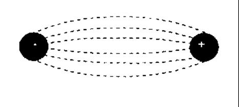
existing between two points of charge.(See Figure
6) Figure 6
Because lines
of flux exist between two opposite charges a dipole transmitting
antenna is not needed. Curry proposed a dipole in order to create
a wave of |
the proper length to be propagated through the medium. However, in electrostatics
it is not necessary for flux lines to detach and close upon themselves
to propagate an electric field. The field is established by the
flux lines between the two points of charge. Curry misunderstood
the nature of the electrostatic field. Once the field is established,
a change in pressure on the charge will cause a variation in charge
at the other end of the field - a displacement current. Also, Tesla points out that a dipole is not needed to
receive even low frequency signals in an electrostatic system.
Tesla pictured his receivers with electrodes spaced a quarter
wavelength apart but this was to charge an unpowered receiver
as rapidly as possible. The receiver's capacitor would see maximum
voltage changes, and, thus, would gain sufficient charge to power
a device, if the ground electrodes had such a
spacing. If, though, "the impulses are... are alternating,
but sufficiently long in duration" they can be received by
a single electrode that is turned on and off with the same period
as the transmitter. Because the field's flux lines do not radiate
but start at the transmitter and terminate on the receiver, the
receiving structure does not have to be a specific shape or length. His patent, then, also describes a through-the-earth,
compact ELF communication system. Today's ELF antenna arrays,
by contrast, require hundreds of square miles for their deployment. Proof of Principle Test This method of electrostatic communication can be tested
by using a grounded, resonant electrostatic detector coupled to
a standard communications receiver, encased in RF shielding to
receive a signal. For demonstration purposes a commercial station
transmitting on 1.16 MHz at 50KW, 40 miles away from the receiver
could be used as the test source. If the transmitter's antenna is feed at 50ohms impedance,
the antenna current is: The quarter wavelength period for 1.16 MHz is: P = 1/4f P = 1/(4)1.16x106 P = 2.16x10⁻⁷ sec. The
amount of charge in the antenna during the quarter period is: |
|
|
|
|
|
|
|
Page 31 |
|
 |
 |
 |
 |
Just for Fun:

Powered byIP2Location.com
Thanks for your time!
Last Updated:
March 1, 2020 22:16