|
Back
to 90th, it happened, that
my power PA begun to produce TVI and very heavy TVI were appeared
only on 40 meters. A low frequency filter that was installed on
the PA had not given any effect. My researches showed me, that
neighbours' TV-sets were overloaded by power signals leaking from
my PA to wire of the main. Most power leaking was only on 40 meters.
I did not know the reason for the damage till now, but I needed
to remove the TVI. What could I do?
Well,
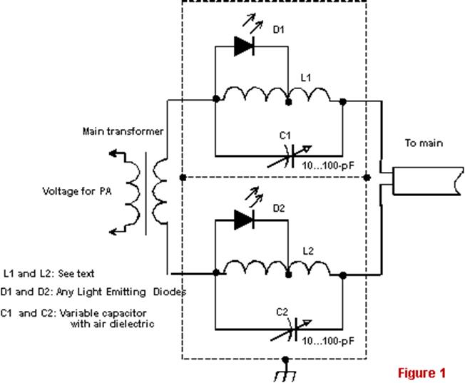
usual rejection circuits (trap) were switched on in main wires,
as shown in Figure 1. And that is all, the TVI were disappeared.
|
For
good rejection the traps should be made as possible best. In my
design, L1 and L2 coils, intended for suppression of frequencies
of range of 40 meters, contained 30 turn of copper wire of 1-mm
diameter (#18 AWG), ID for the coils was 2.5 cm, length was 4
cm. LED was connected to seventh turn of the coil. Air dielectric
variable capacitor of 10-100-pF is used for each trap. Figure
2 shows the design of the traps. Please, Note, Figure 2 is not in scale.
The traps were
placed in a box made from PC board material. The box was disposed
directly on the back panel of my PA. The trap box should be connected
to main transformer of the PA by short, as it is possible,
|
|
wires. If a free
place is near a main transformer inside a PA the trap box can
be placed at this place. The PA case was grounded by 3 cm width
copper tape.
Tuning: Trap must be tuned to the middle of the amateur frequency
band. Figure 3 shows how to do this. Each trap is connected
to a PA, loaded at a dummy load, through a capacitor of 10-pF.
Out power in 10-W is enough for tuning the trap. By variable capacitors
C1 and C2 do maximum glow from LEDs D1 and D2.
|
Having
installed the trap box in the PA, switch the PA to transmission
mode and once again tune fine the traps by C1 and C2. If the LEDs
too shine out, decrease tap number from the coils. When traps are tuned,
it is possible not
disconnected the LED from coil.
On
my view, set-up the trap by a PA is very conveniently. However,
the way is not sole. For example, a GDO gives good result also.
At this method the trap is tuned to needed resonance frequency.
Other method is to use a RF-voltmeter
|


