

|
|
 |
 |
 |
|
|
Antentop is FREE e-magazine devoted to Antennas and Amateur Radio an
Special page devoted to
Old computer's PSU gives useful parts for antennas

Custom Search
|
ANTENTOP-
02- 2003, # 003 |
Old computer's PSU |
||
|
|
|||
|
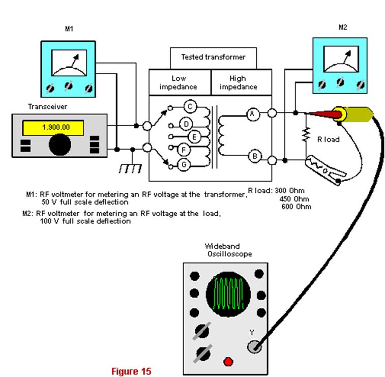
Finding the efficiency by RF voltages |
|||
|
Here P is in watts, V, I, R are in volts,
amperes and ohms. A transformer load resistance is known. Transformer's
input resistance was early obtained by the circuit shown in Fig. 13. Thereby it is easy to find the efficiency.
Note: The efficiency of
the transformer was defined when a RF power of 10 watts gone to
the transformer. Both above described methods gave almost identical values
of the efficiency for my RF transformer. However all the methods
demanded special measuring RF equipment, such as an RF ammeter,
an RF voltmeter or an RF oscilloscope. Not each of hams has the equipment. So I used
one more method for finding of the efficiency. The method is named
'a method of a poor ham', because it does not demand any RF measuring
equipment! A method of a poor ham If
a ham has not any special measuring RF equipment, he can use an
indirect method for definition of the efficiency. Fig.
16 shows the measuring scheme for the indirect method.
The RF transformer is connected to a transmitter having a |
variable power. An
incandescent bulb is bridged to the primary winding of the RF
transformer. Other incandescent bulb is connected in serial with
a load resistor at the load side. The bulb and the resistor form
a load for the RF transformer. I used incandescent bulbs of 26-V/0.12-A both at the primary winding
side and at the load side. The common resistance (a serial resistor
+ a bulb) should provide one of standard load resistances - 300,
450 or 600 Ohms. Tab. 6 shows needed values of the serial resistor
for forming the standard load resistances. Columns of Tab. 6 contain two values of the serial resistor.
The upper value is a calculated value. The down value (in brackets)
is the closest value of a standard resistance to the calculated
value. Note: The serial resistor was calculated under the hypothesis,
that the incandescent bulb has 216 Ohms when 26 volts of RF is
across this one (26 volts/0.12 amperes = 216.6 Ohms). Certainly,
a bulb has a different resistance at the same value of direct
or RF current through it, so, the bulb gives not the same shining
at the same value of direct or RF current through it, but for
our case the difference in the shining is very small. |
||
|
|
|||
|
|
|
||
65 66 67 68 69 70 71 72 73 74 75 76 77
 |
 |
 |
 |
Just for Fun:

Powered byIP2Location.com
Thanks for your time!
Last Updated:
March 6, 2020 22:40