

|
|
 |
 |
 |
|
|
Antentop is FREE e-magazine devoted to Antennas and Amateur Radio an
Special page devoted to
Plasma Antenna Technology

Custom Search
|
ANTENTOP-
03- 2003, # 004 |
Plasma Antenna Technology
|
|
|
|
|
Tunable
Plasma Frequency Selective Surfaces for Shielding Radar Systems |
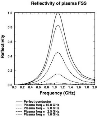
This theoretical plot is of the plasma FSS array illustrated
above. Each dipole element is assumed |
|
|
to
be in length, in diameter. The vertical separation |
|
Schematic representation of an FSS dipole
array
|
is taken to be while the lateral separation is taken
to be The plot has the curves for the perfectly conducting case
(high plasma frequency and density)
along with those for several values of the plasma frequency, which
depends on plasma density. A well-defined reflectivity resonance
exists at 1GHz. This result indicates that appreciable reflection
occurs only for plasma frequencies above 2.5GHz. The results illustrate
the essence of the plasma FSS: a highly reflective band stop filter
can be achieved which can be switched on and off simply by controlling
the properties of the plasma. -Navy Phase I SBIR Contract N00178-03-C-1013 January
2003 - This contract intends to develop a |
|
This sketch illustrates a finite section of an FSS
dipole array. The array elements are the vertically aligned rectangular
regions. The horizontal lines on the rectangles indicate the way
in which the elements are broken up into segments for the purpose
of defining current modes. |
gas plasma antenna array architecture
capable of meeting the broad Navy objectives for future shipboard
radar systems. We are proposing a compendium of plasma technologies
that could be integrated into existing radar suites or be designed
into future revolutionary radars. These technologies are plasma windowing, plasma waveguides,
plasma |
Plot
of ASI's theoretical model
|
Frequency Selective
Surfaces and flat parabolic arrays (FLAPS). ASI Technology Corporation developed
under contract with General Dynamics Electric Boat Division and
in conjunction with the Plasma Physics Laboratory at the University
of Tennessee, an inflatable plasma antenna. This antenna operatedat 2.4 Ghz and was designed to mount on the mast of an attack submarine. We have also demonstrated
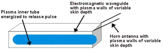
prototype plasma waveguides and plasma reflectors to General Dynamics. Plasma Waveguide with
energized tube as a switch acting as a window for a pulse The following discussion illustrates
why there is military and government support for plasma antenna
concepts. The gas plasma antenna conducts electron current like
a metal and hence can be made into an antenna but with distinct
advantages. The following technological concepts are important
to plasma antennas: |
|
|
|
|
|
Page 28 |

 |
 |
 |
 |
Just for Fun:

Powered byIP2Location.com
Thanks for your time!
Last Updated:
February 26, 2020 21:40