|
For experimental operation
on the 6-meters range some antennas for others bands with ATU can
be used, especially if a radio amateur only starts to work on the
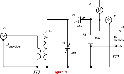
"magic" band. Schematic for such ATU that does match any
antenna of 10-20 meters to 6-meters is shown on Fig. 1.
The
ATU allows match a load of 15 to 1000 Ohms with 50- Ohms coaxial
cable or with end stage of the transceiver. Efficiency is not less
than 70 %. The ATU has L2C1 resonant circuit that kills TVI very
well.
Of
course, to install the ATU between the antenna and the coaxial cable
is the best way for the RF power going to the antenna. In this case
you can connect the antenna to J3 and the coaxial cable to J1. Of
course, the situation is impossible at many cases, because it requires
install the ATU straight by the antenna terminals. So, more often
we have only one way - connect the coaxial cable going from the
antenna to J2 and the transceiver to J1. The coaxial cable going
from the antenna will work with high SWR and maybe, with large losses.
But we will have possibility work in the ether at 6-meters.
Some words about parts of the ATU. L2 consist of 8
turns of copper wire of 2.0-mm or #12AWG. The coil is air wound,
OD is 16-mm diameter, the length is
|
24-mm.
L1 consists of 3 turns of copper wire of 1.0-mm or #18AWG. L1 is
wound above "cold" end of L2. The length of L1 is approximately
5-mm. R1 serves for removal of static voltage accumulated by the
antenna. J1 is intended for coaxial cable going to the transceiver.
J2 is intended for coaxial cable feeding antennas. J3 is intended
connection to the antenna terminals or for feeding the antenna through
a ladder line. J3 is just two screws of diameter of 3-mm.
ATU
is tuned with help of a Neon bulb VL1. You can use any small neon
bulb. One clip of the bulb is connected to the antenna a piece of
wire of length of 3- 10-cm (depends on the transceiver power) is
connected to other clip. Tune the ATU to the maxima of glow of the
bulb. If you use a QRP- transceiver you can use a FSM (Field Strength
Meter) for the tuning.
Do
tuning in this way. Firstly C2 stands to minimum. Secondly, with
the help of C1 do tune the L2C1 to the resonance (by the neon bulb
VL1). Then gradually do augment capacity of C2 to maxima of glow
of the neon bulb VL1. C1 and C2 can be aerial dielectric, and plate clearance should be 0.5-mm to 30 watts bypass
power. .
The
ATU is assembled inside a box soldered from PC- board. Box has dimensions
100*70*50 mm.
|


